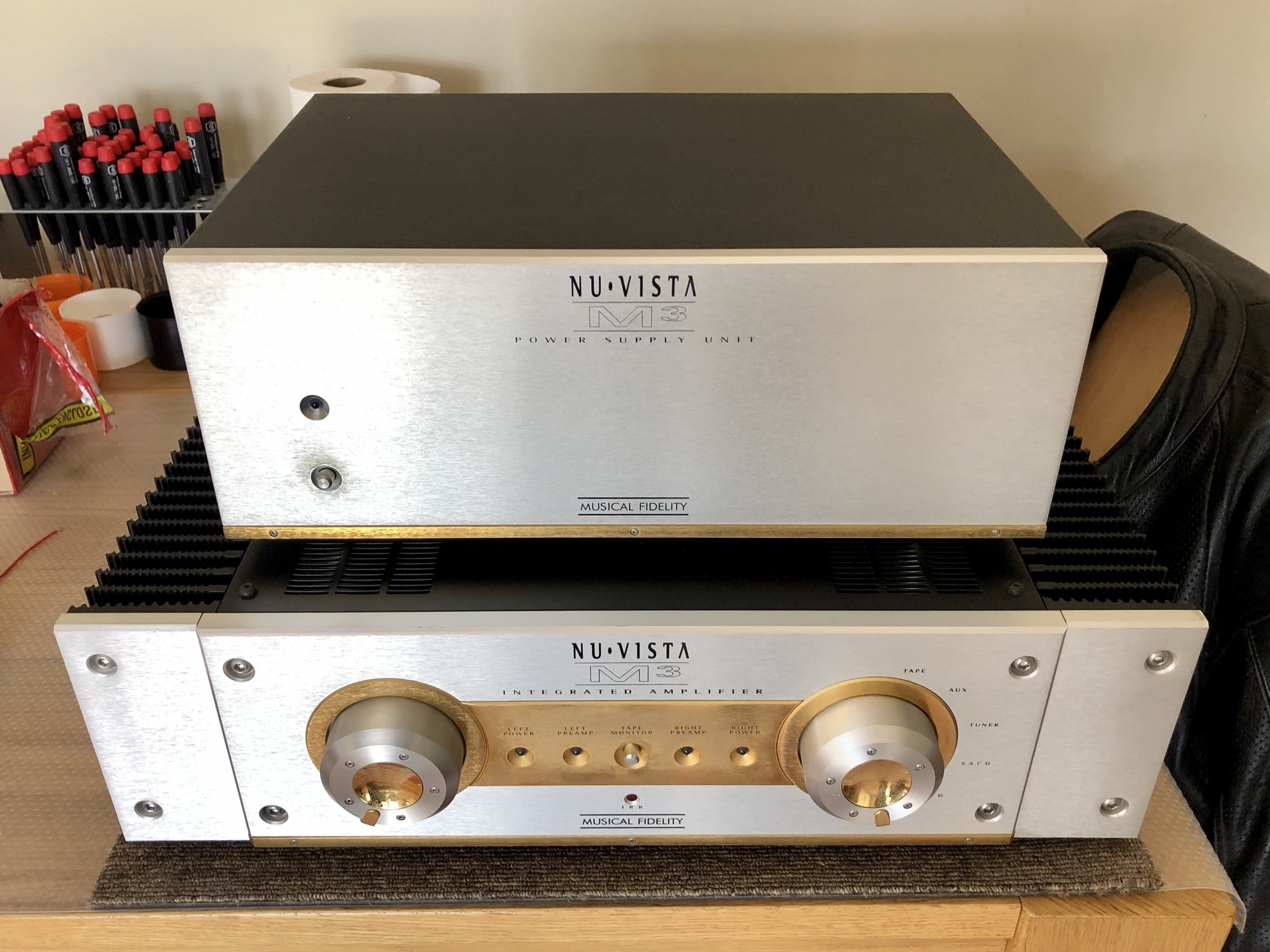
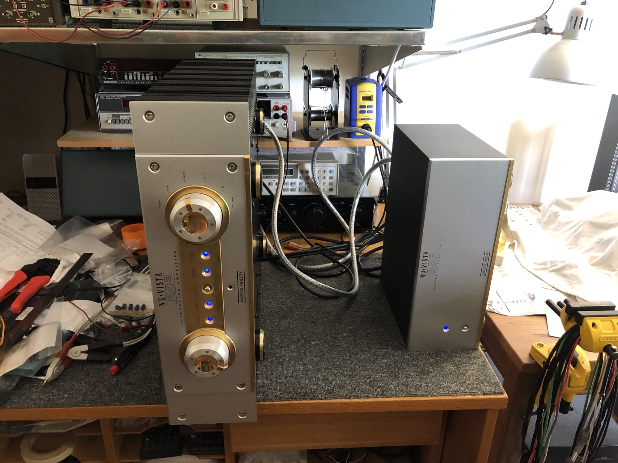
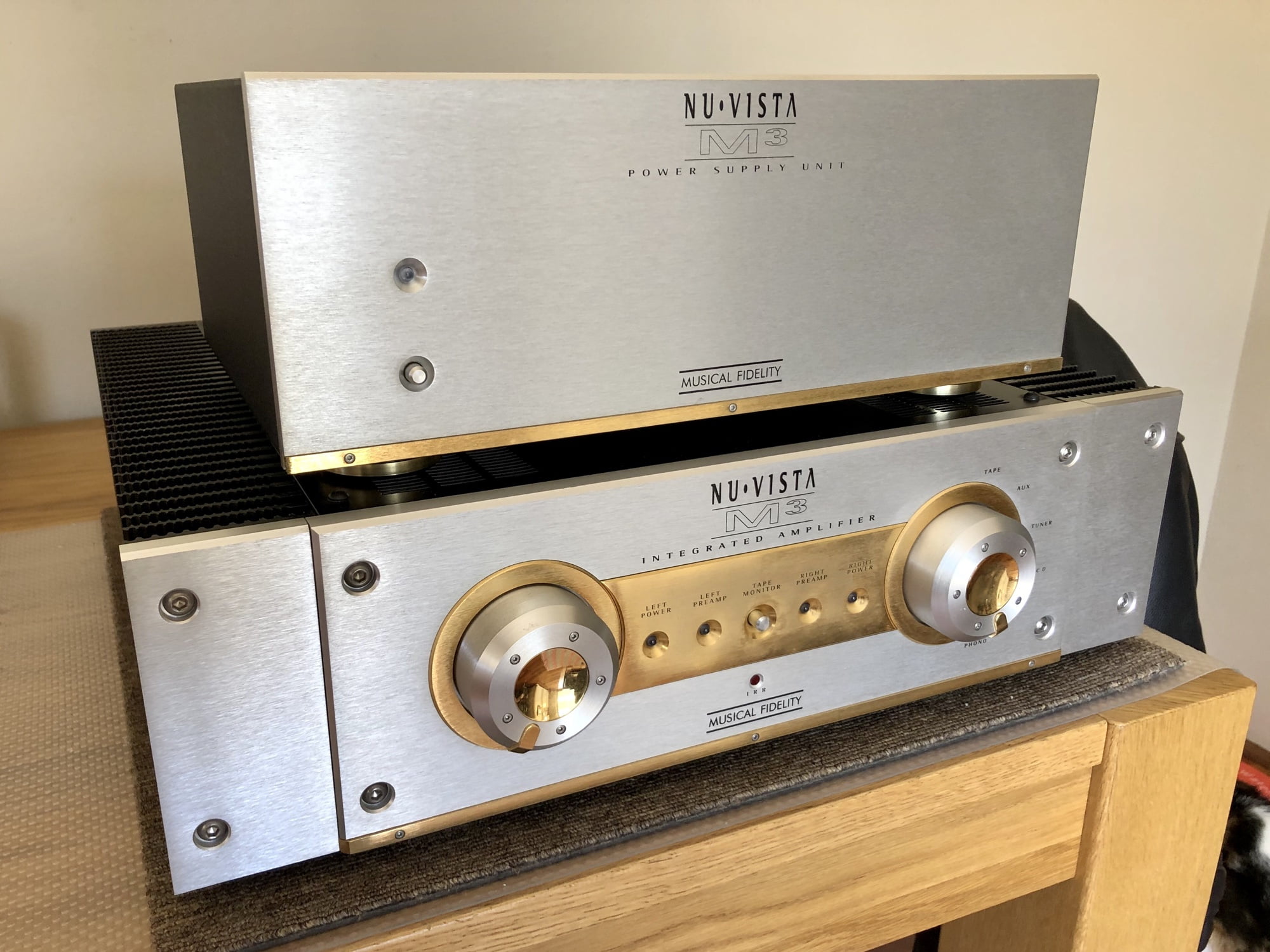
I recently repaired and serviced this monster Musical Fidelity NuVista M3 integrated amplifier. Come with me as we take a look inside.
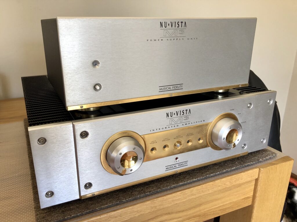
The Musical Fidelity NuVista M3 Integrated Amplifier is a true two-box monster amplifier. The NuVista M3 was one of Musical Fidelity’s statement products back in 2001. Back then it cost $4500 USD and that was a heck of a lot of money! If you’d like more of a review article, try this, from Stereophile.
Design
Unlike conventional designs, the Musical Fidelity NuVista M3 consists of two large and heavy boxes. The smaller box is the power supply. It actually houses transformers and that’s it, so it isn’t really a power supply, more a transformer cabinet. Three heavy-duty cables link these transformers – left power, right power and preamplifier – to the main amplifier chassis.
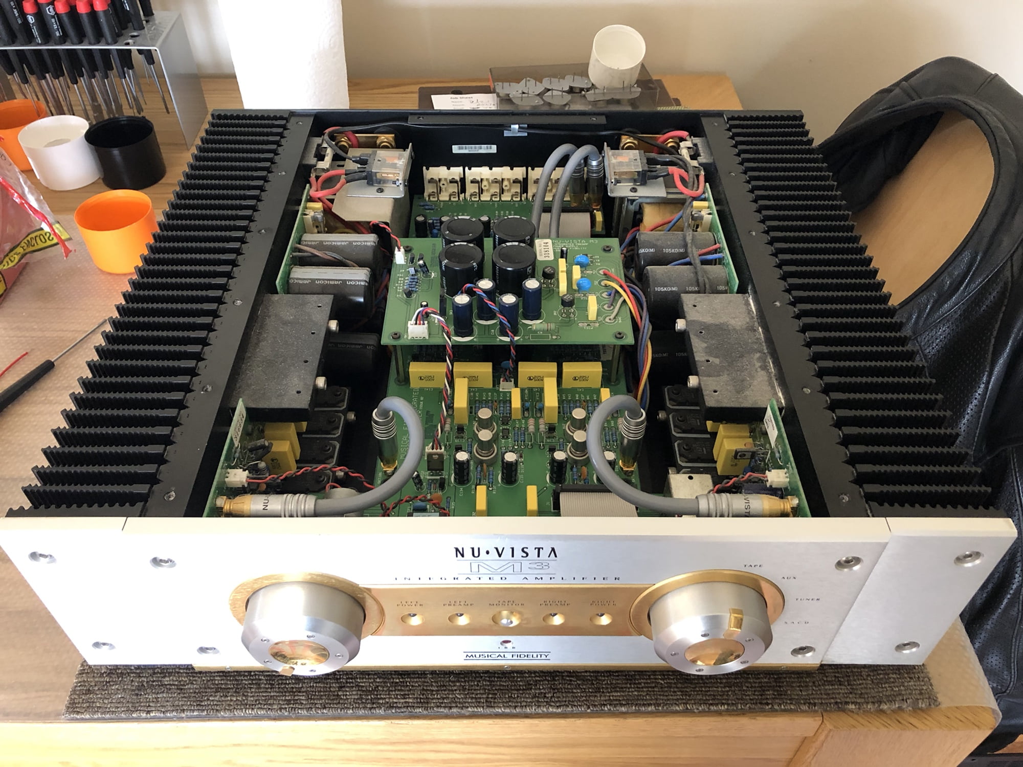
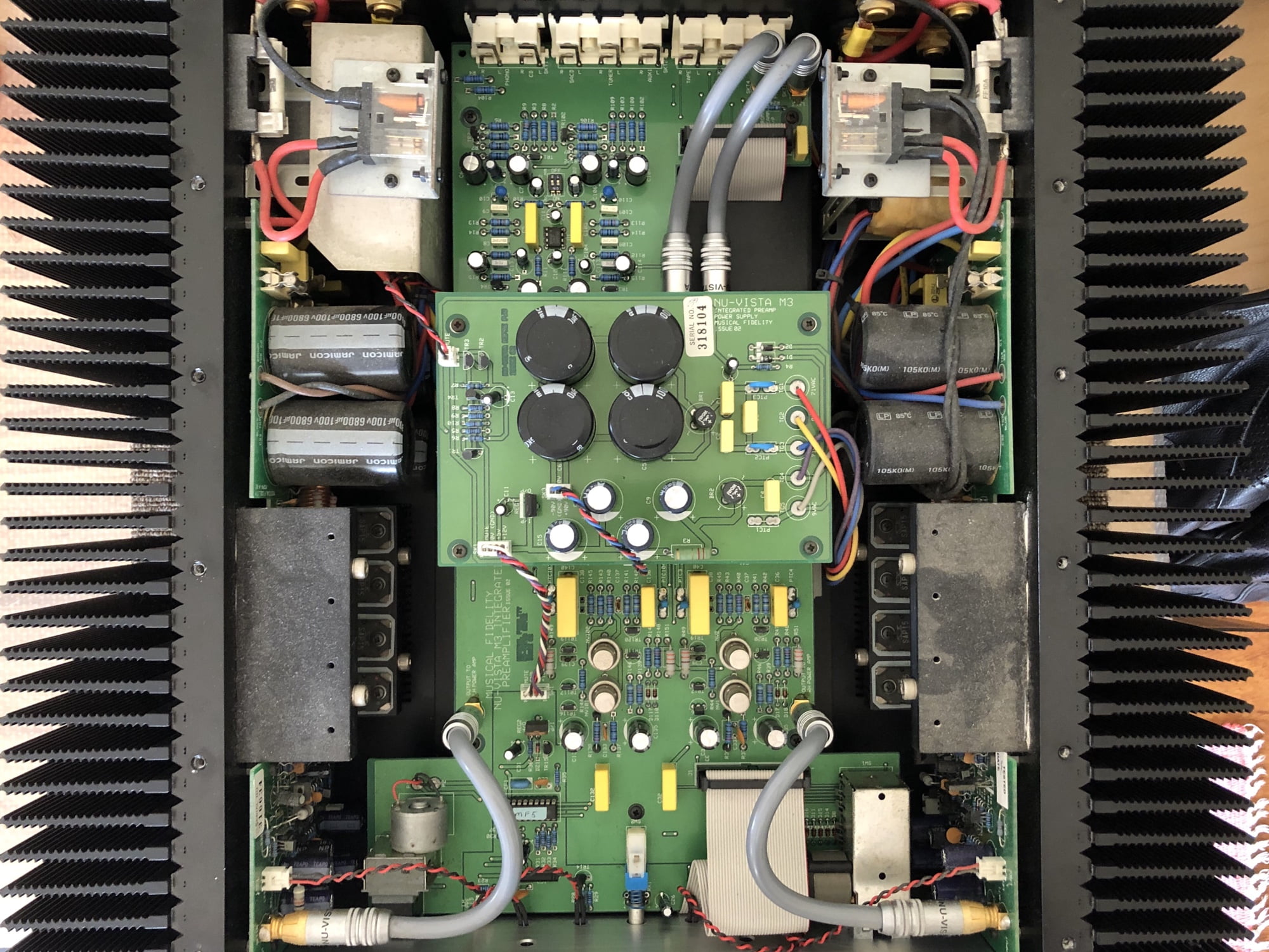
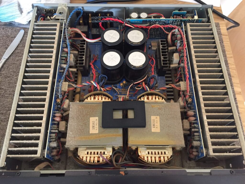
The second, larger cabinet holds the rectifiers and filter capacitors, preamplifier circuit and power amplifiers. The circuitry is straightforward and the quality of the parts is quite basic, in typical Musical Fidelity style. Board quality is good and the modular design is again typical of MF. There is nothing unusual here, except maybe the Nuvistor tube buffer implementation, which is cool.
In terms of other design elements, the Musical Fidelity NuVista M3 uses Sanken SAP15 Darlington output devices. Each unit consists of two bipolar transistors, a diode and an emitter resistor in a high-gain configuration. This reduces the number of components needed in the drive circuitry but creates its own issues.
These devices are no longer available though and are hard to match due to their inconsistently high gain. If this thing blows up, it could be a pain to fix now, especially if you can’t get access to the large number of devices you’ll need to select an adequately matched set.
Musical Fidelity NuVista M3 Specifications
Power Output: 250 watts per channel into 8 Ohms
THD: (Typically) < 0.003% at 1kHz (‘A’ weighted)
Frequency response: (Typically) 20Hz – 60kHz +0.25 / -3dB
Inputs: 1 phono 5 line level
Outputs: Speakers, Tape out, Preamp out.
Input sensitivity: (line) 300mV, (MM) 3.5mV
Input impedance: (line) 100KOhm, (MM) 47KOhm
S/N Ratio: (line) (Typically) 102dB A-weighted
S/N Ratio: (MM) (Typically) 83dB A-weighted
Power consumption: 1200W max
Power requirements: 100/115/230V AC 50/60Hz
Dimensions: Amplifier 482 x 145 x 470mm (W x H x D)
Dimensions: PSU 365 x 145 x 250mm (W x H x D)
Weight: Amplifier – 23kg (un-boxed); PSU – 16kg (unboxed)
Previous Work…
This late serial numbered unit had visited a technician prior to its arrival here. This technician had replaced parts as part of an expensive repair job. In this case though and much to my relief, things were, for the most part, neat and tidy.
The issue, and I’m not sure if this had occurred to the owner, is that this work didn’t resolve the problem with the amplifier and was therefore completely unnecessary and expensive, with no net positive result. The original channel drop-out problem with this NuVista M3 returned shortly after the work done a few years ago. My customer lived with this for some time before bringing the unit to me. Can you pick the new parts in the image below…?
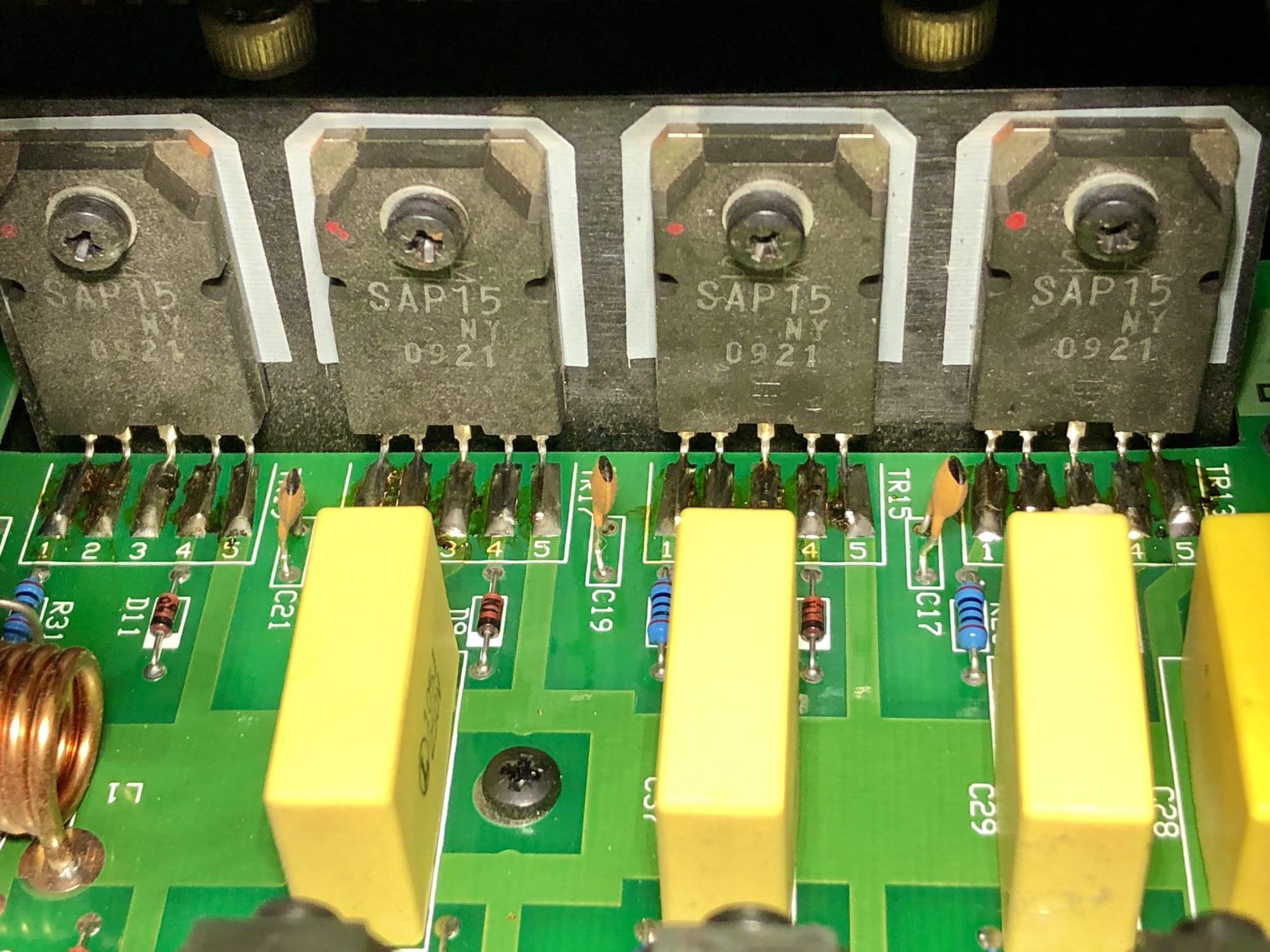
So, I found a set of 16 SAP15 Darlington devices from 2009 in this amplifier from 2001. As I said, the work is neat so I have no problem with it from that perspective. The problem is that it didn’t need new output devices. This work cost the owner well north of $1000 AUD.
The original fault returned shortly after the output devices were replaced. This tells us that they were absolutely OK. The amp still ran at this point and these things usually explode when they fail, leaving signs that are visible even after replacement. These devices are used across a range of MF amplifiers and they generally fail catastrophically.
Issues
One of the first things I do with any piece of equipment exhibiting a recurring fault is to carefully examine every component possible. I’m looking for clues (thanks, Robert Palmer), signs of damage or overheating, poor soldering or anything that might exhibit intermittent poor contact, like a switch or relay.
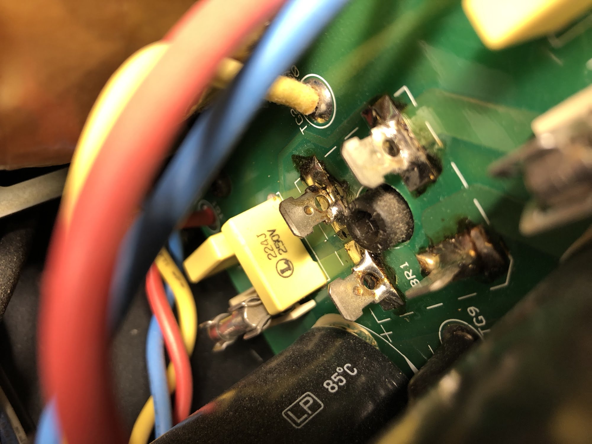
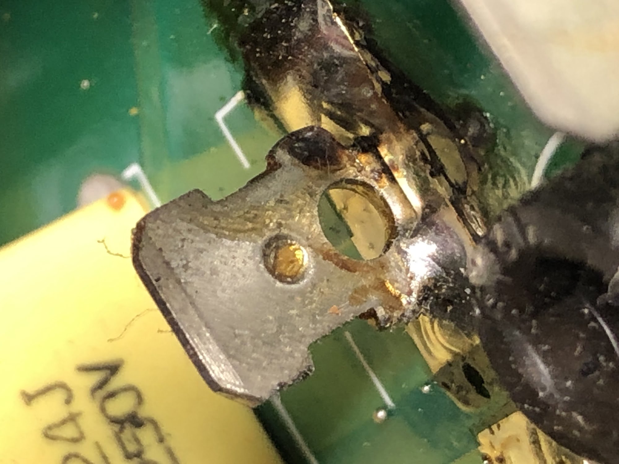
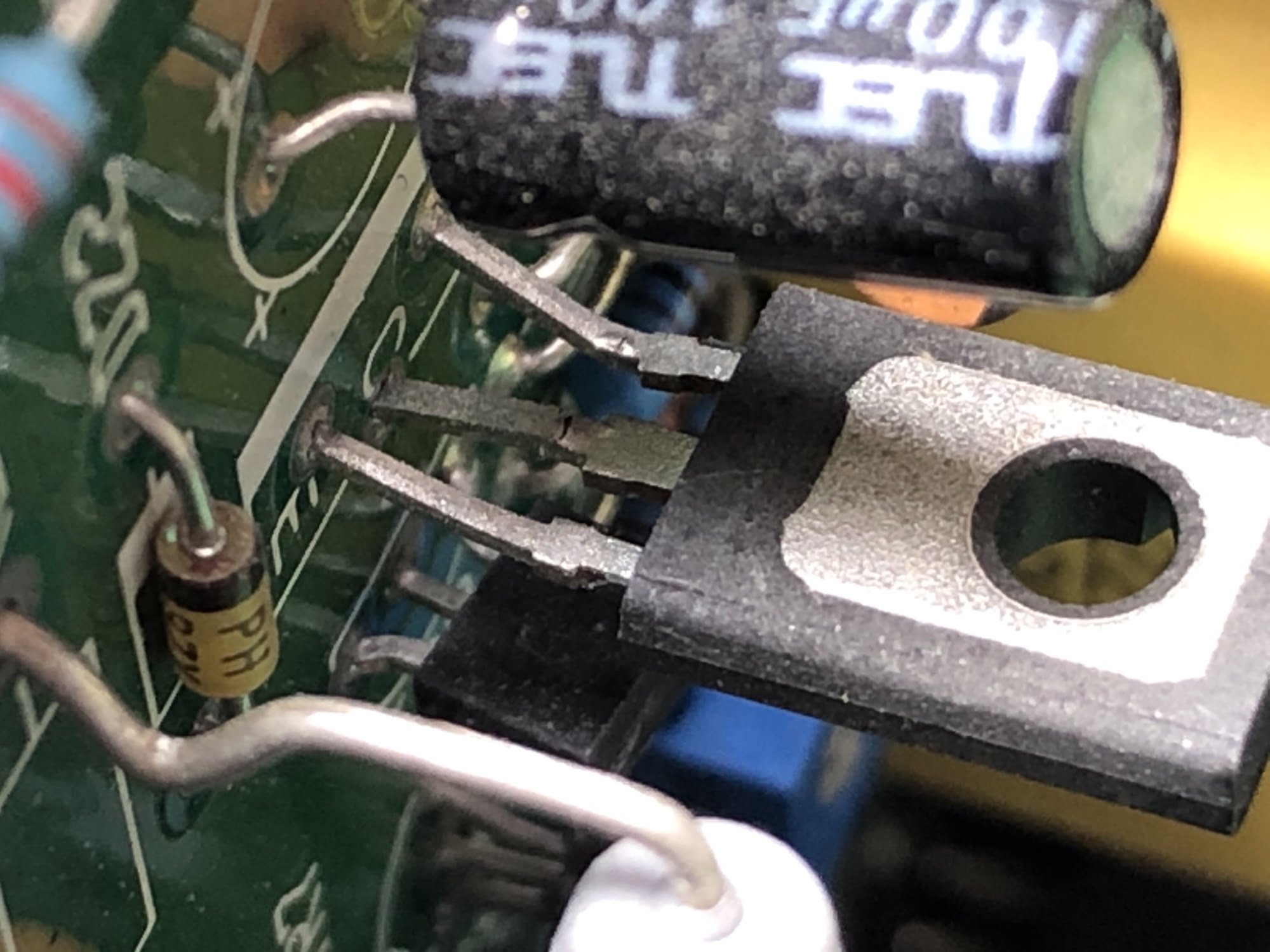
I found three critical and two potential issues in this NuVista M3:
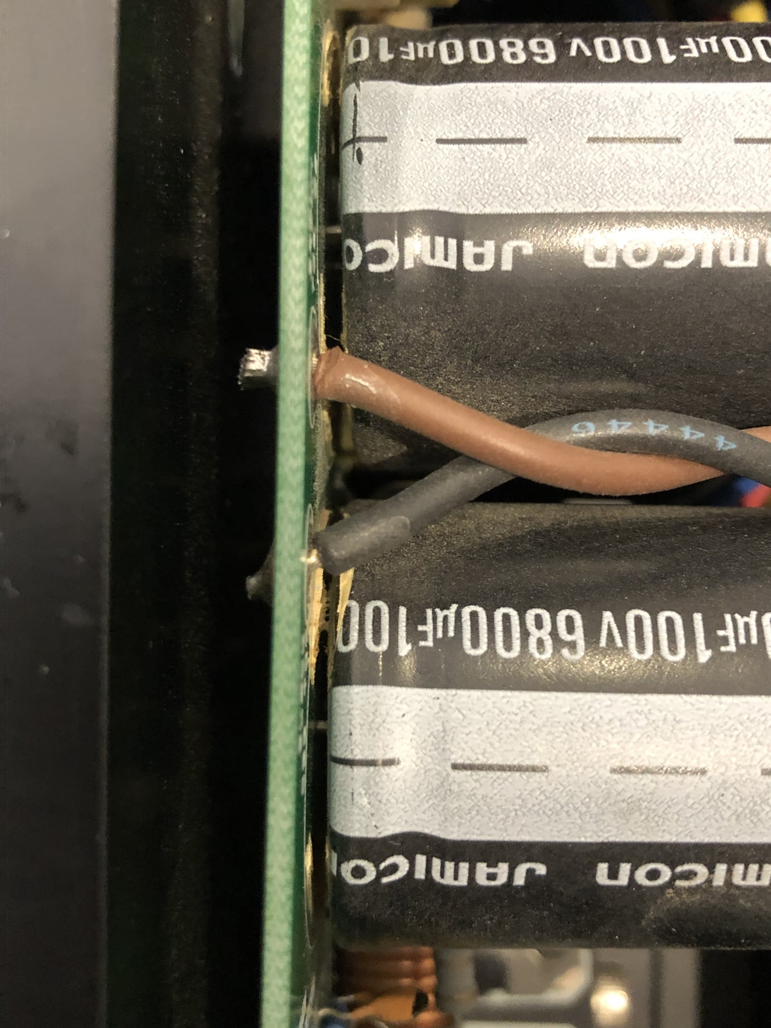
- A damaged TO-126 device (inflicted during the previous repair)
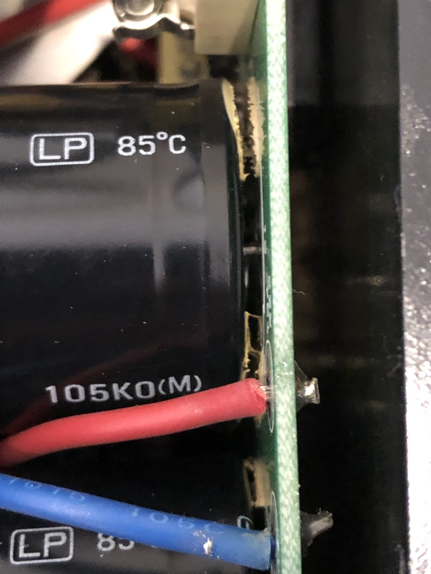
- Poor soldering on a diode bridge
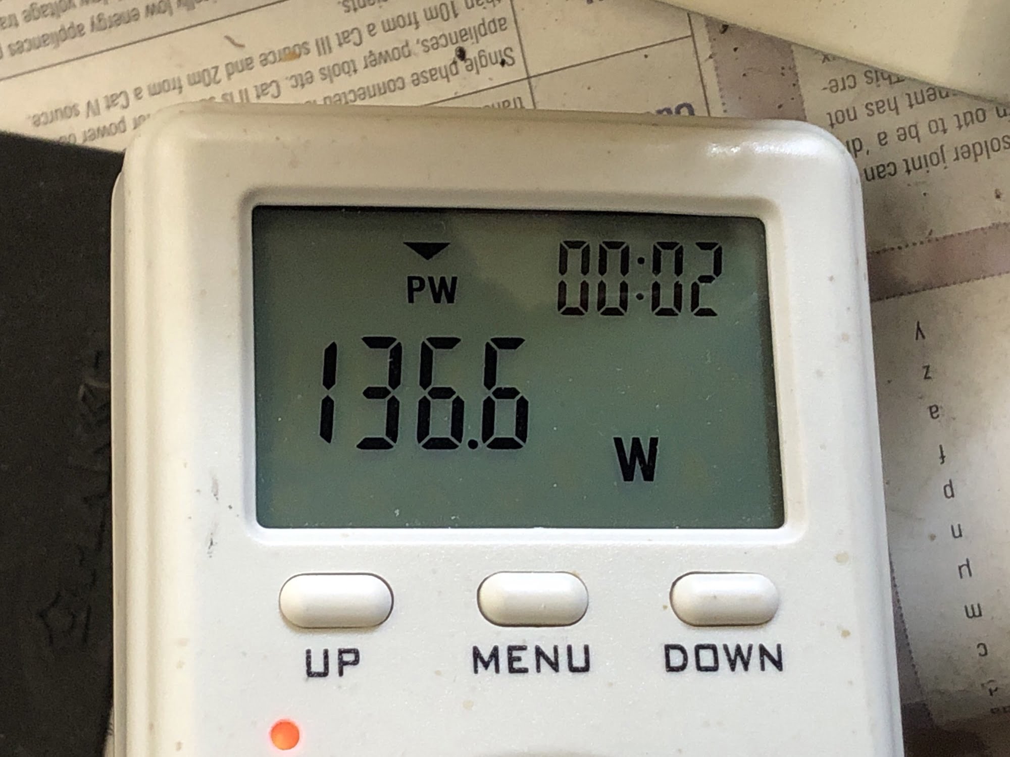
- Excessive idle power consumption and asymmetrical bias
- A remote-controlled mechanical input selector – potentially flaky
- A full complement of crappy original capacitors
Repair & Service
First, I repaired the poorly soldered diode bridge and the TO-126 transistor with the fractured legs.
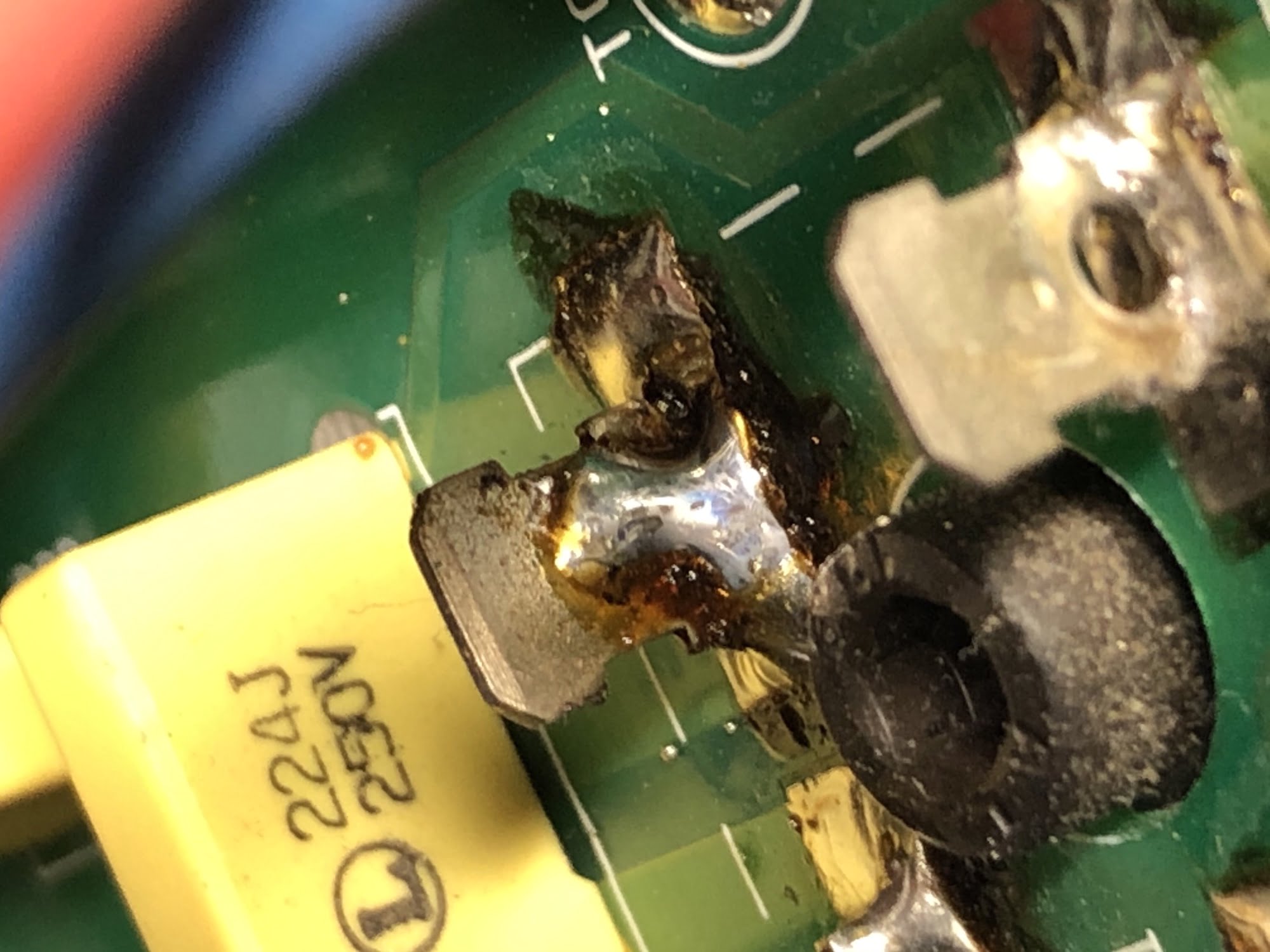
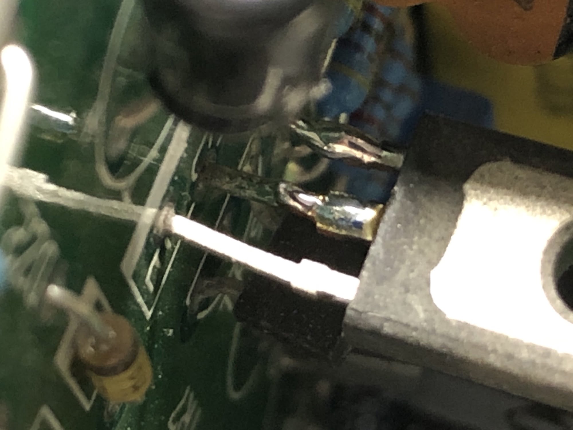

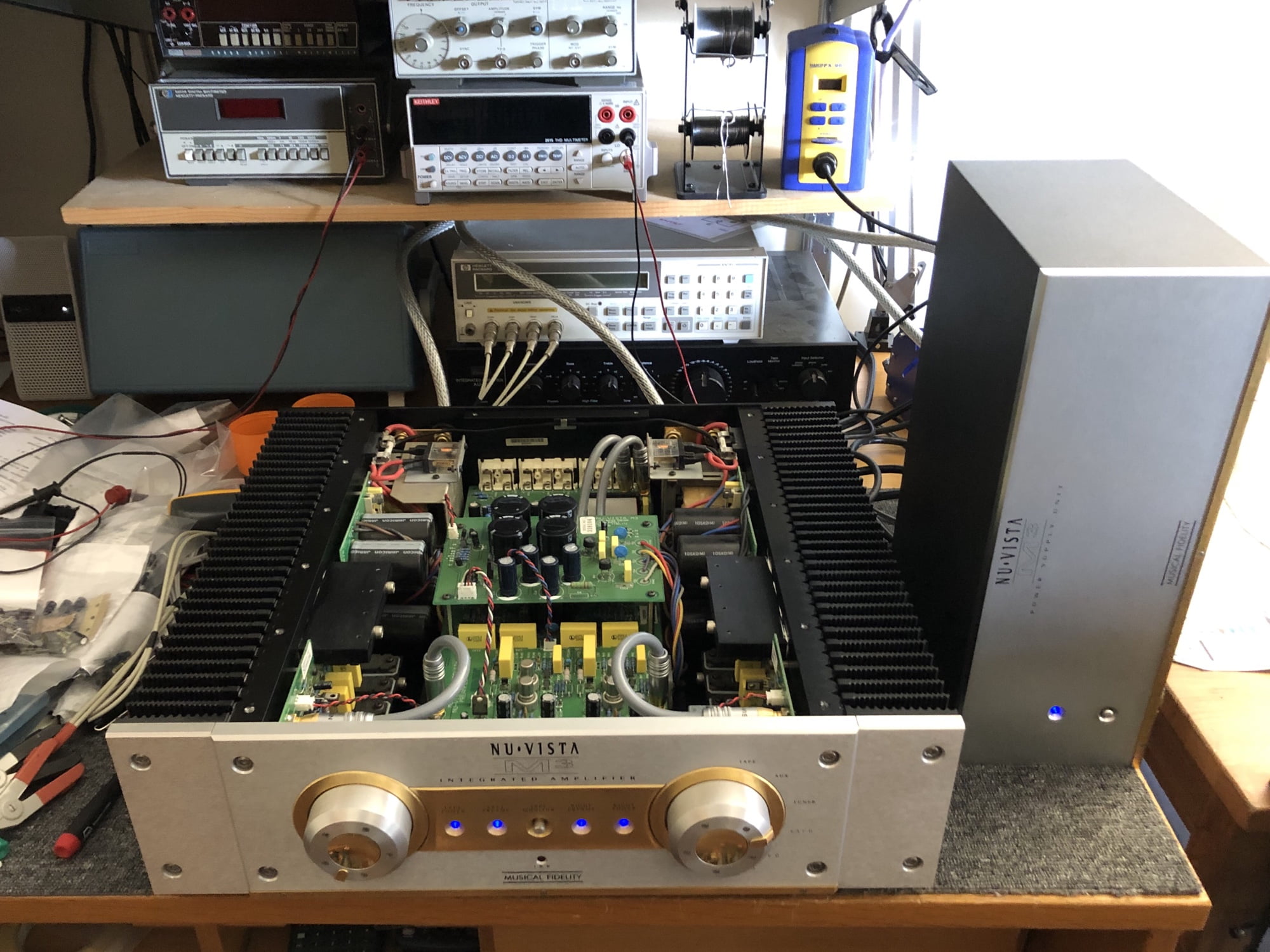
So what were the main issues here? When the output devices were replaced in the previous repair attempt, the technician failed to correctly re-bias them. He either misadjusted the quiescent current or never looked at it at all. This caused a thermal imbalance and poor sound and this, combined with a flakey input selector switch were the likely culprits. The damage he caused to the transistor was incidental but not a good thing.
Results & Suggestions for Improvement
After addressing the problems with this Musical Fidelity NuVista M3, including the poor soldering and fractured transistor legs, extensive bench testing and adjustment, I gave her a clean bill of health. Listening to the M3, she sounded lovely, particularly BIG, powerful and clearly capable of driving big speakers in larger rooms.
The only other thing I recommended to her owner is an overhaul, using better parts in critical locations and some other improvements that I know work well with all Musical Fidelity gear. This will transform the performance of an M3 in sonic terms, as well as improve its reliability.
To anyone owning a Musical Fidelity NuVista M3 integrated amplifier and wanting the best performance and reliability, a full overhaul including new filter capacitors, improved film capacitors and additional critical bypass and decoupling with some special NOS vintage parts is the prudent way to proceed.
Feedback from her owner is extremely positive:
Dear Mike
I thought I would let you know that my amplifier has never missed a beat since getting it home, thanks so much, I really appreciate it.
Dennis
My customer is bringing her back next year for this work and if you or anyone you know has one of these or any of the other big Musical Fidelity amps, I am very happy to service, repair and overhaul these units.
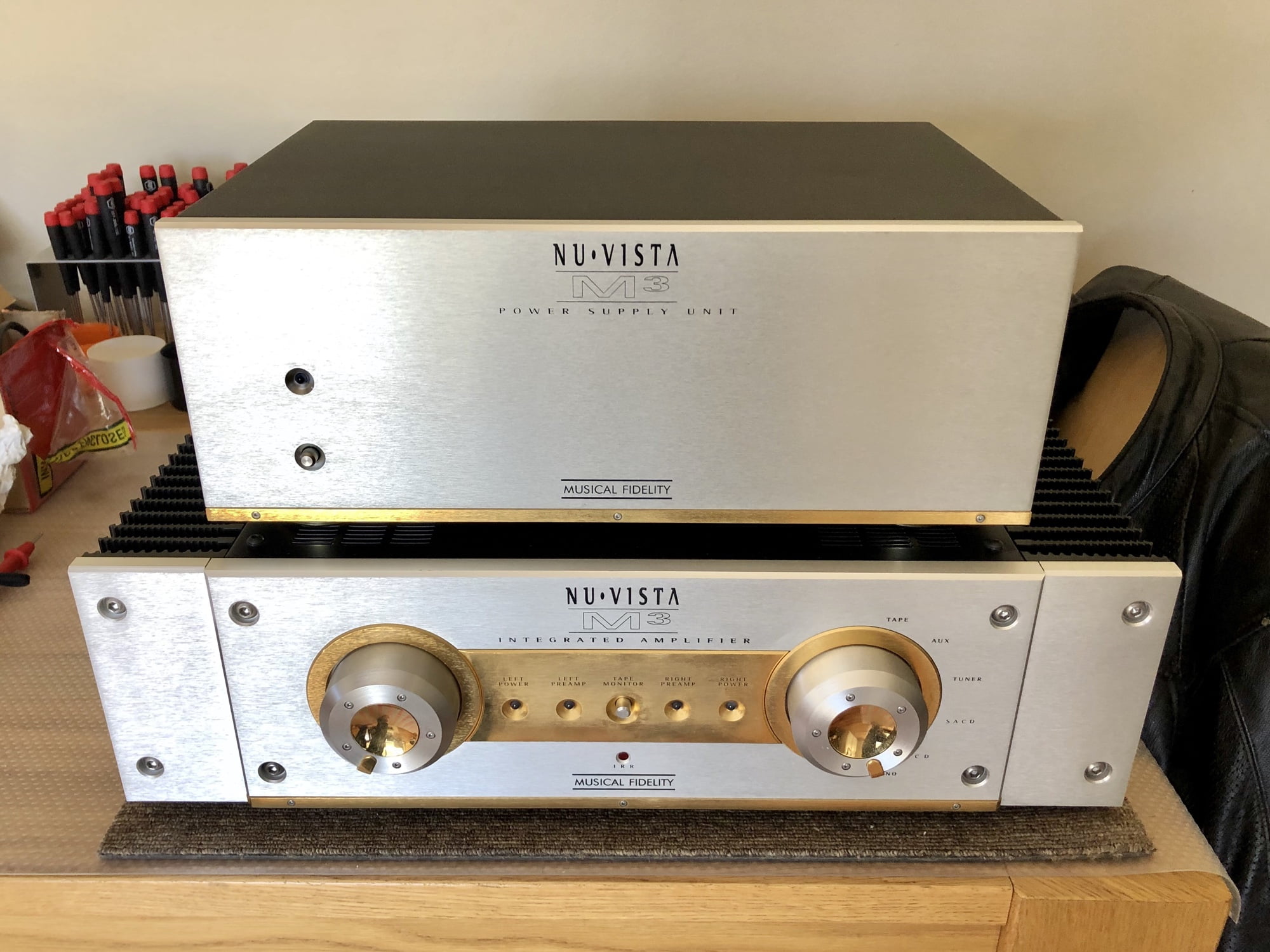
As always, thanks for reading. If you would like me to service or repair your Musical Fidelity NuVista M3, or any other lovely Musical Fidelity equipment, don’t hesitate to let me know.

Hi Mike, interesting article, I own a Nu Vista M3 as reviewed.
great sounding amp. I love it !
Where do you service these amps ?
I’m in South Australia & would like to up-spec my unit,
it works beautifully at present. its just had the original selector switch refurbished. Couldn’t find a replacement selector switch. would do if I could ?
Anyway its rare & good gear that I would like to preserve & may improve.
Even If I could buy just a replacement selector switch ?
Cheers Drew email: mobybass10@gmail.com
Hi Drew, thanks for your comment! All customer equipment is serviced by me, here in the Liquid Audio workshop. This includes gear from WA and around Australia, plus a tiny bit from overseas. There are many things that can be done to improve these amps but good to hear yours is running well. I’m helping a technician in Canada with one as we speak.
I am familiar with this model. It is yet another Musical Fidelity abortion. Here is a further list of design flaws:
* The use of NLA Nuvistor valves. Dumb.
* The method of attaching the NLA output devices relies on an EDGE mounted slab of aluminium plate. Thermal transfer is particularly poor. I measured an almost 20 degree C difference between the temperatures on the output devices, relative to the main heat sinks. Not unusual for MF. They have a poor reputation for getting thermal issues right.
* The use of Jamicon main filter capacitors. These are cheapest, poorest quality caps commonly available.
* Agreed with all the other findings. The M3 is a terribly designed product.
* A personal issue, to be sure, but the M3 is seriously garish and horrible to look at.
The reason I happened on your page is because I am working on an ancient MF A-200DM. Looking at the A-200DM, it is clear that MF have learned very little from their earlier mistakes and cheap-arsed approach to design and manufacture.
Hi Trevor and thank you for your assessment of this classic MF amplifier. There are some typical MF design issues here and many owners of these amplifiers have been hurt by reliability issues. That being said, many other amplifiers are worse than this and these at least sound nice, when they are working. My comments on your assessment:
* MF liked using weird NLA parts. It’s not the smartest design decision but they are at least reliable in this role. The output devices are a bigger problem.
* I addressed the thermal and heatsinking issues and yes, the heatsink arrangement is poor. I disagree with your assessment of other MF amplifiers, thermally speaking.
* I disagree in terms of caps, Jamicons are FAR from the worst out there. Suntan, Samxon, Lelon and many others are way worse and all too common, unfortunately.
* I also dislike the gold trim and garish styling.
Agreed with the comment about Jamicon caps. They are certainly horrible and there are worse caps. Consumers should expect more when paying big Bucks for such a product. In fact, in your area, where mains Voltages can be (ahem) patchy, there is one model MF amp I worked on a few years back (sorry, I don’t recall the model number), where 8 or 12 Jamicon main filter caps were used. The caps were rated at 63 Volts. The rail Volts (at a regulated 230VAC) was 60 Volts! Almost all the main filter caps were dead. Terrible design. I seem to recall the heat sink fins were horizontal too. Made it easier to lift. Shame about the cooling.
Also agreed with the comment about output devices. I like Sanken semiconductors. They’re pretty good, BUT, Sanken have a most unpleasant habit of deleting products from their range and frequently no substitute is available.
BTW: I gave up trying to re-engineer the A-200DM. I just fixed the amp and issued the client with a warning. When clipped briefly, the amp exhibits severe crossover distortion for several second and the level must be reduced to around 10% of maximum power for bias stability to return. Weird AND horrible.
FWIW: Back when I was with Marantz, we used to send out the most spare parts (given the number of products sold) to our Perth agent. When I questioned him, he explained just how horrible the mains supply could get back then.
Does any one have the schematic for the musical fidelity m 3 power amp .
I need to repair one .
Stuart .
Hi Stuart, my name is Mike, I run Liquid Audio and yes I have this and most other MF service data. Whilst I am not permitted to share manufacturer-supplied service data, if you have technical questions, you are welcome to use our advisory service, accessible via the contact page and I’ll do my best to assist.
Hi Mike,
I repaired one of these amps last week. It arrived missing the input switch mechanism as well as other issues. Someone else had been at it before me!
I understand from the owner that he contacted you but sought some one in NZ because of the shipping costs.
I tidied up many things including stressed capacitors mounted between the heatsinks of the regulators of the Preamp PSU. I can’t understand why so many items come in with electrolytic capacitors next to heatsinks. I know they should be reasonably close to the regulators, but not a few mm from the heatsinks. In this amp 2 caps are between the 2 regulators and the heatsinks, a little hot box arrangement.
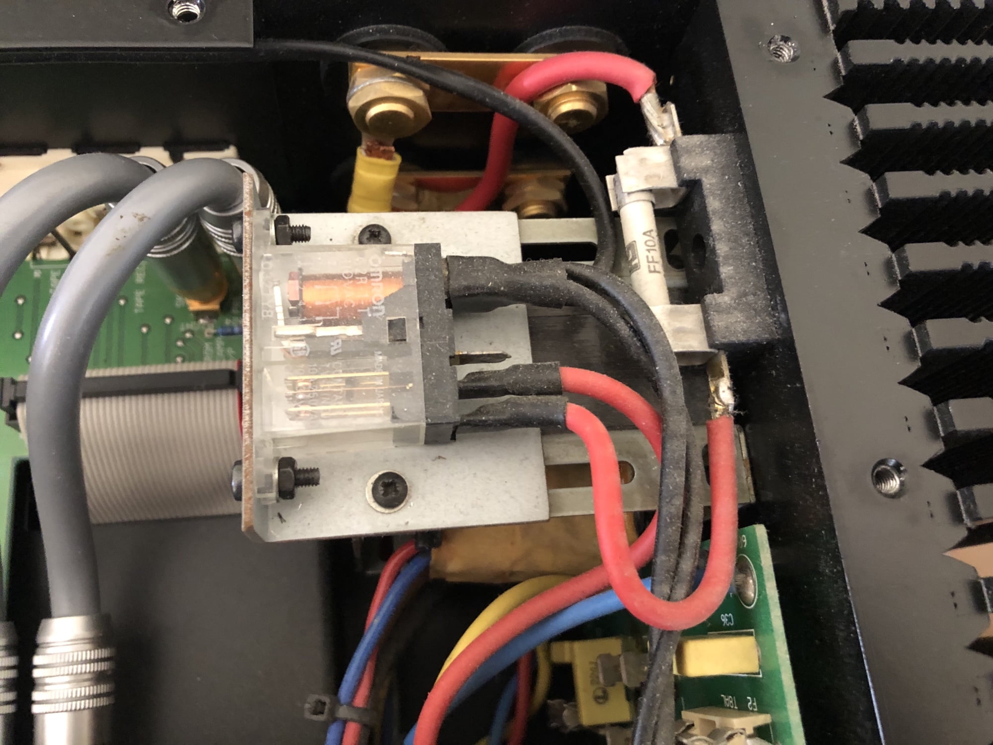
A one channel cutting out issue was the speaker relay going open due to stress caused by the connecting cable being too tight and distorting the relay enough to open the contacts as the amp warmed up.
As far as I can tell, the output relays only prevent the switch on thump at turn on and don’t offer DC protection for the speakers. Also the relays are definitely an afterthought as they are driven from a delay relay glued underneath the preamp PSU board.
At the owner’s agreement I replaced the relays with a stand-alone speaker protection board and removed the speaker fuses.
Like you, I am unimpressed with some aspects of the amp but it does sound good.
I am now working on a Nu-Vista-800 integrated amp. Two output devices on one channel went short. The owner had a go at it himself but quickly realised he didn’t have enough knowledge or suitable tools. It came with a full set of replacement semiconductors for the power amp so no issues for me sourcing rare Sanken 4 lead darlingtons! It’s going now but I’m just working on the bias for the repaired channel as it’s significantly lower than the other channel. I’ve figured out what I think it is. I’ll know soon!
kind regards,
Marcus Wilson.
Hi Marcus, thanks for your thoughts and yes, if it’s the guy I’m thinking of, we had a chat on the phone about his MF Nu-Vista 800 amplifier. I can source the graded and matched output devices (very important) from MF, but they are expensive. There are some hokey design aspects with MF amplifiers which is a shame. They do usually sound pretty good when running well, but just aren’t quite well enough designed or built for the money in terms of the Darlington output devices, Jamicon caps, op-amps and single-ended topology, etc. Anyway, best of luck with the repair.
Mike thanks for the reply.
The 800 is working fine now and finished.
I agree, darlington’s are not good as output devices on audio amps. Doug Self has a lot to say about this. (If you read his books.)
Hello, im currently trying to repair my M3 which problem is a high noise coming out from both speakers, i have already changed a set of nuvistors without any resoult, is there any chance you can share at least part of the schematics of preamplifier section?
It would help me a lot, as a gesture of help i can also share some unobtainable documentations of krell, Mark levinson or top sansui gear, thanks
My e-mail is Raziel4m@gmail.com
Hi Marius and thanks for getting in touch. I’d love to assist but I’m not permitted to share manufacturer-supplied service data and cannot jeopardise my relationships with manufacturers and distributors by doing so. Rather than replacing parts, any undocumented or non-factory modifications should be reverted and then the fault traced to its origin. This will likely require separating pre/power blocks and signal tracing with an oscilloscope, but it will reveal the source and relieve your stress I’m sure! If you cannot do this, I suggest finding a good technician. This will minimise wasted time and money, and reduce the chances of causing harm to this lovely piece.
Hello there,
not sure if u had a chance to read thru the article https://www.audiosciencereview.com/forum/index.php?threads/musical-fidelity-nuvista-m3-integrated-rebuild-mods.18285/
What do you think about these changes?
I own the amp, there are no issues, sometimes i am getting temporary snorting (from L channel).
I am based in the central Europe, so it would be very hard to ship it for some inspection etc…
Any ideas?
Thanks!
Hi John, thanks for sharing the link, I’ve not seen it before or looked at it yet, but that’s not surprising. I generally avoid such things as I’m self-contained, not reliant on external input and often find things that are erroneous, misinformed, etc which annoys me. Hovering on the link I see my name, hopefully that’s a good thing, perhaps I’ve helped someone with their repair..?! I have another M3 here with me for repair and improvement, there is (thankfully) a ton of room for improvement in all MF gear. Would love to help with yours but agree that sending it here is basically impossible.
@Mike
thank you for your response… yes as its heavy i dont believe transportation will be possible.
Is there a way how to share your improvements and send spares etc… for $?
I might try to find someone here locally to just replace as per your advice…
Have you had a chance to go thru the mentioned link?
Another issue that I have with my m3:
Since time to time (randomly) when i power on PSU it Trips my Circuit breaker. I was not sure whats going on so I disconnected AMP from the PSU and tried to power on the PSU only. Even here, it sometimes trips my CB.
I was not sure if CB is issue, so i tried different socket/circuit ie different CB … but it happened also.
I emailed some UK service partner and they send issue to MF. The lead MF engineer responded that my 16A CB is inadequate. He proposed that i use 16A CB with D curve so it can sustain higher inrush current.
Here is the spec of the D curve https://docs.rs-online.com/6abf/0900766b802d9c09.pdf
When I started to question the proposal … ie how did he come up to the CB with Curve D, he changed his mind and said that i should not replace CB because it can damage PSU/AMP.
Then he said they cant help here anymore and i have to send PSU for the inspection.
Any idea here? Thank you so much!
Hi John, no problem, though I’ve not checked the link and don’t supply BOMs, parts or other details of my work, so I’m unable to assist in that sense. That said, your amplifier needs repair rather than improvement so that should be the focus. I suggest taking her to a trusted local specialist comfortable working with larger amplifiers. Your 15/16A circuit and breaker are not the issue here. This is regular consumer equipment and if there is an inrush current issue, this should be measured, diagnosed and repaired. All the service data is available via MF or their distributors and trusted technicians will be able to access this. One thing is for certain – this will be very repairable in the right hands!