I decided to build a resistance standard, for use with my test and measurement gear and good enough that I could some calibration on test and measurement equipment owned by other people.
I wanted to build something that would not be prohibitively expensive and that would allow me to reliably calibrate the resistance ranges of my two Keithley bench multimeters and various Fluke hand-held DMMs to at least 0.01% accuracy. An accuracy of 0.01% is definitely better than my hand-held meters are capable of, but less than the 24 hour 0.002 – 0.004% the bench meters are rated at.
It is important to give these ratings some perspective though. A calibration to 0.01% accuracy means that a 1KΩ resistor could read as high as 1000.1Ω, or as low as 999.9Ω. This pretty tight and it is certainly better to know that your meter is known calibrated to better than 0.01% accurate, than to be capable of 0.002% accuracy but in a completely unknown state of calibration.
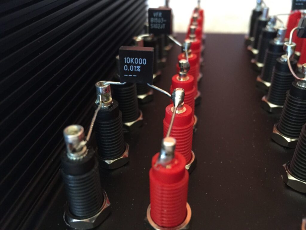
There are a few things to consider when building a resistance standard. First, one must consider the level of precision required. This will determine the type of resistors to buy. I went mostly for Vishay film types, with 0.01% specified accuracy and a crazy-tight 2ppm temperature coefficient. In practice they will all be considerably better than this, but they are only guaranteed to be good to within 0.01% of the specified value.
Another factor to consider is whether you want two or four wire measurement capability. The two-wire method is OK for quick, low-precision measurements, but readings are influenced by many factors like test lead resistivity per meter, cleanliness of terminals and lead length. The main issue with two wire measurement is when measuring low resistances, where the total lead and contact resistance is added to the resistance being measured. With very low resistances, lead and contact resistance can amount to a significant error. Keithley for example estimate that the error introduced by lead and contact resistance can vary from 10mΩ up to 1Ω! Part of the problem is this variability and the unknown contribution made by the test lead setup.
In the table below, which I’ve adapted from a Keithley document, it is clear that the two-wire method creates a significant measurement error when measuring a 1Ω device. This is assuming only a 20mΩ lead resistance, which is optimistic. If the lead resistance were higher, the 2% error could quickly become a 10% error or worse.
The four-wire, four-terminal sensing or Kelvin method is the best method to use where accuracy and repeatability are important as it nullifies the effects of lead and contact resistance. The Kelvin measurement method, useing four test leads, deficates two of the leads to carry the current forced through the resistor being measured, sourced from a low impedance. The second set of leads are used to measure the voltage drop across the test resistor at the resistor itself.
The test instrument input impedance is very high for voltage measurement, typically around 1MΩ, hence almost no current flows into the test instrument through the voltage test leads and their contribution (perhaps 1Ω in 1,000,000 Ω) is so insignificant, it can be discounted. Lead and contact resistance are effectively taken out of the equation, because the current flowing through the voltage sense leads is so small and the voltage drop in these leads is negligible. Resistance measurements are more repeatable using the Kelvin measurement method and with all four terminals per resistor, two wire measurements can still be made when needed. For these reasons I have chosen to make a four wire standard.
It is very important to consider everything that might influence the measured resistance when building a resistance standard. It’s not good enough in my opinion to simply say “get a resistor, connect two wires to it and whack it in a box.” To do things correctly, one must consider minimising the chance of noise entering the system, contact and lead resistance, so that two wire measurements are as accurate as possible. As most DMMs have a set of four banana terminals, I have opted to buy banana patch leads, ie leads with banana plugs at both ends, and female banana sockets for the resistance standard. I have chosen a set of four Hirschman 32A banana patch leads, 50cm in length. For the resistance standard itself, I have chosen Deltron female banana sockets, silver plated for the lowest contact resistance. For absolute precision, every element must be considered in the final equation. Silver is the best conductor, even when tarnished and it retains its conductivity over decades.
So far then, we have Vishay 0.01% resistors, four Hirschmann test leads, 20 or so black and red Deltron silver plated banana sockets and of course we need a box. I am going to use a Hammond black extruded aluminium box. The banana sockets can easily be fitted to the top of the box.
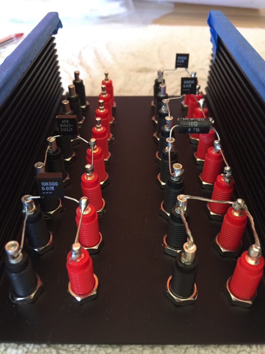
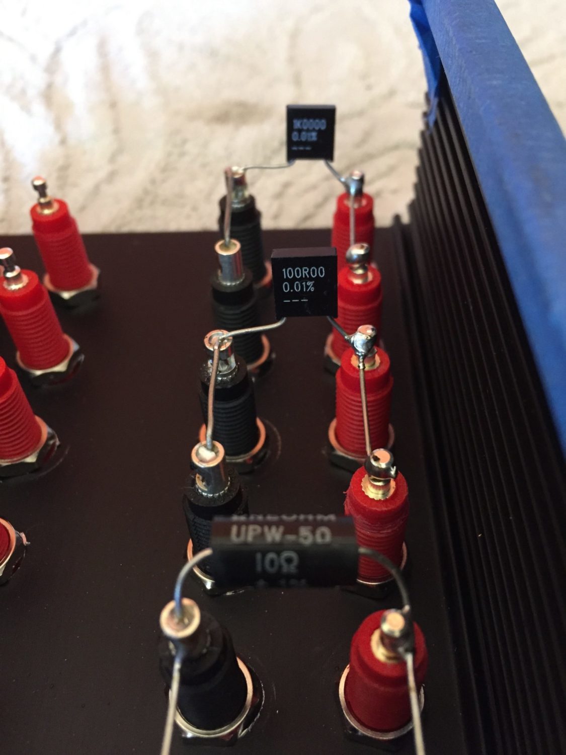
I looked up the service manuals of my 5.5 and 6.5 digit Keithley and HP multimeters before deciding on parts. In the end I chose to go with 10R, 100R, 1K, 10K, 100K, 1M, 10M values. The 10R, 1M and 10M resistors are actually 0.1% parts as there was nothing I could find in 0.01% and the 0.02% resistors were too expensive. I can easily change the parts out in the future for better resistors as I find them, so this is of no real concern.
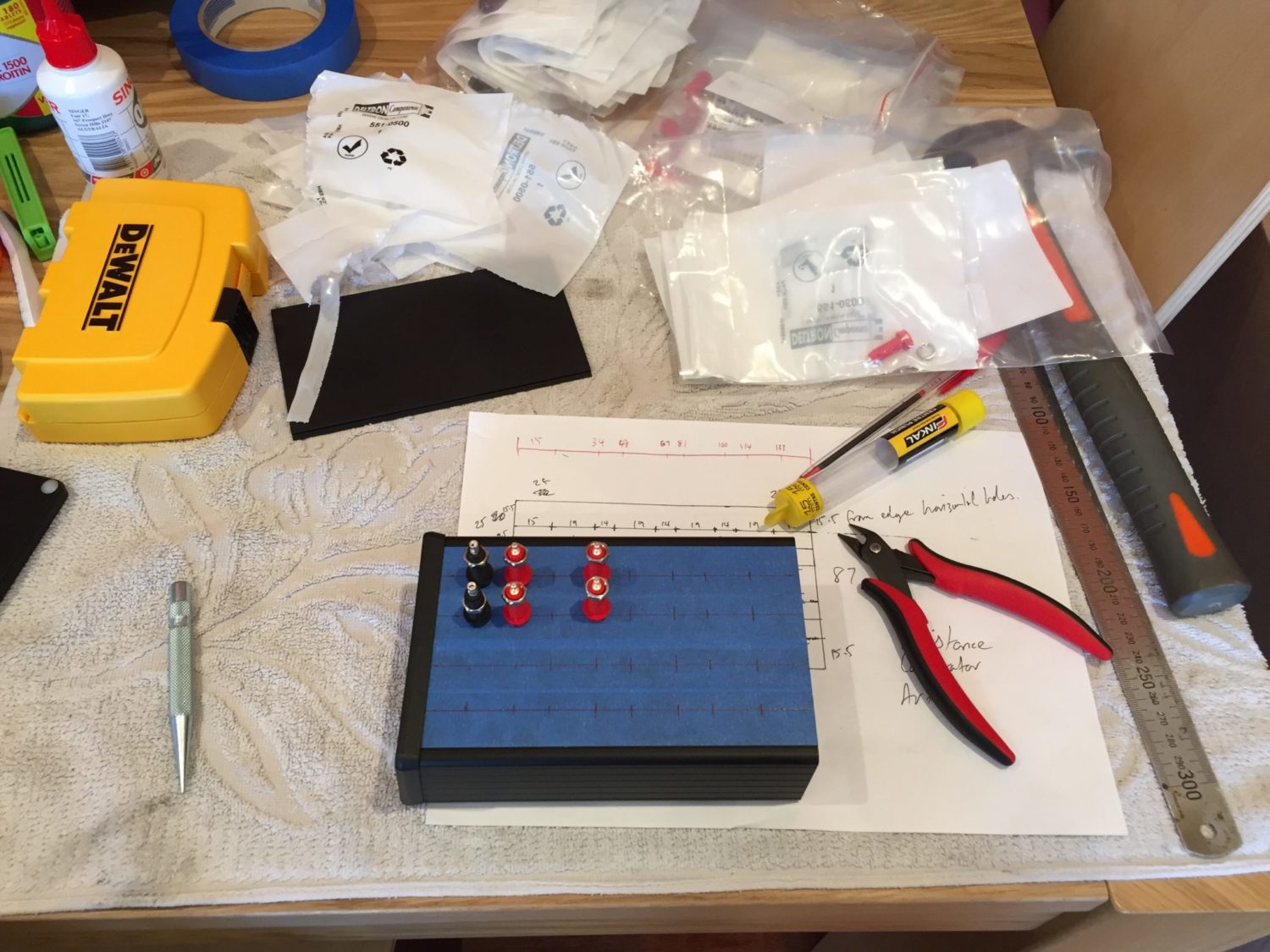
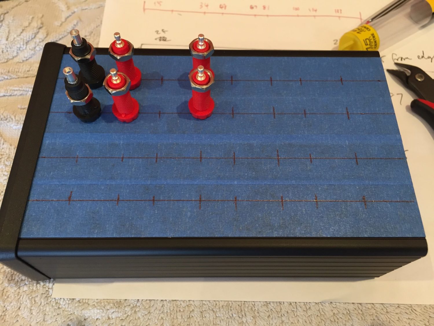
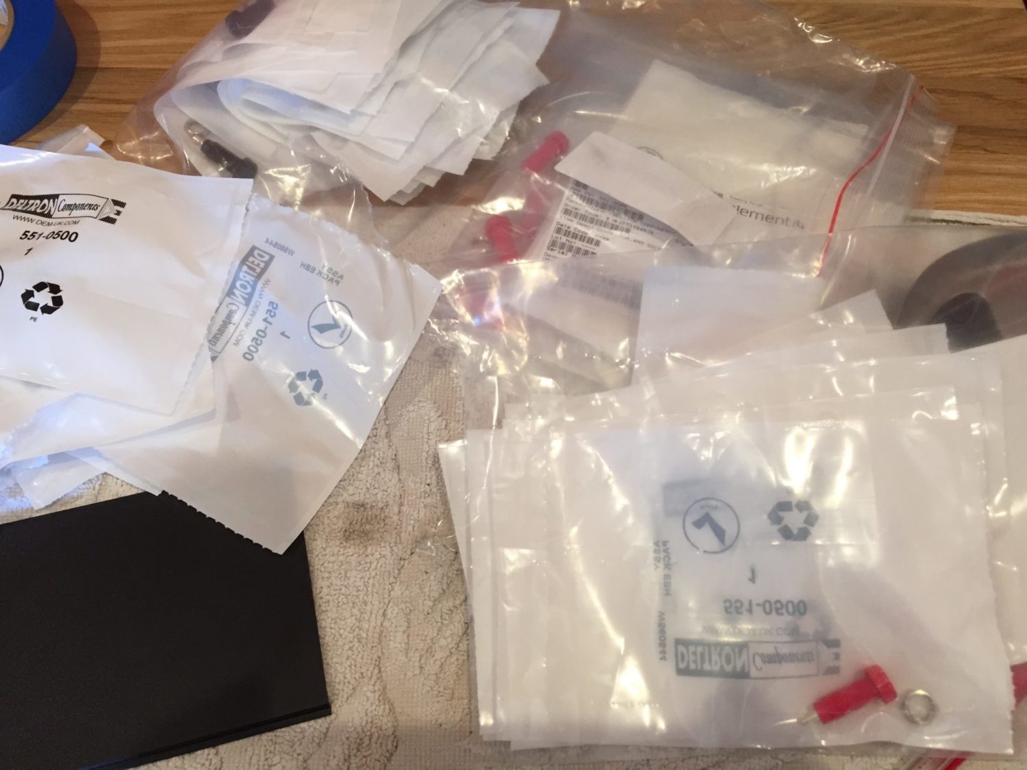
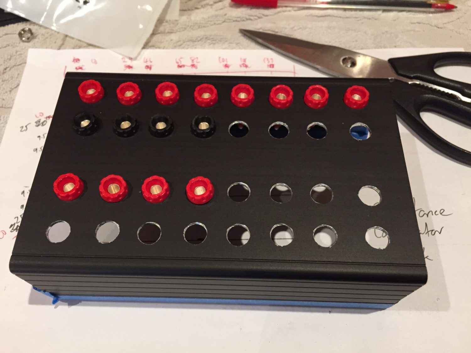
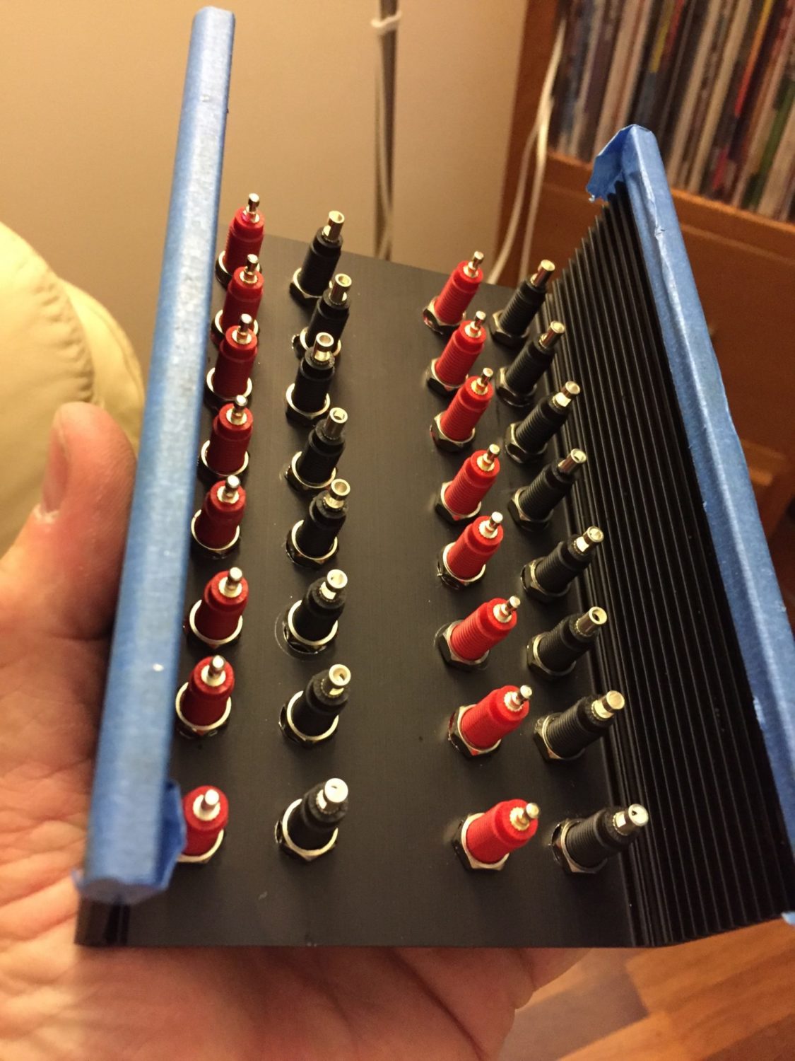
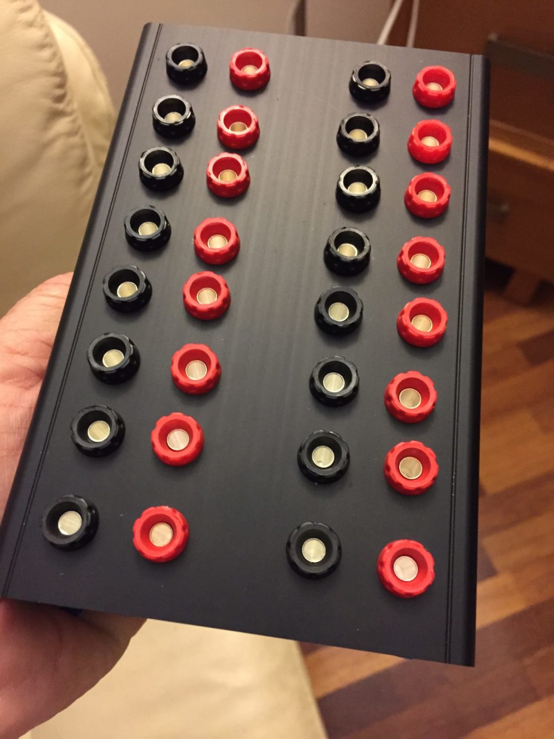
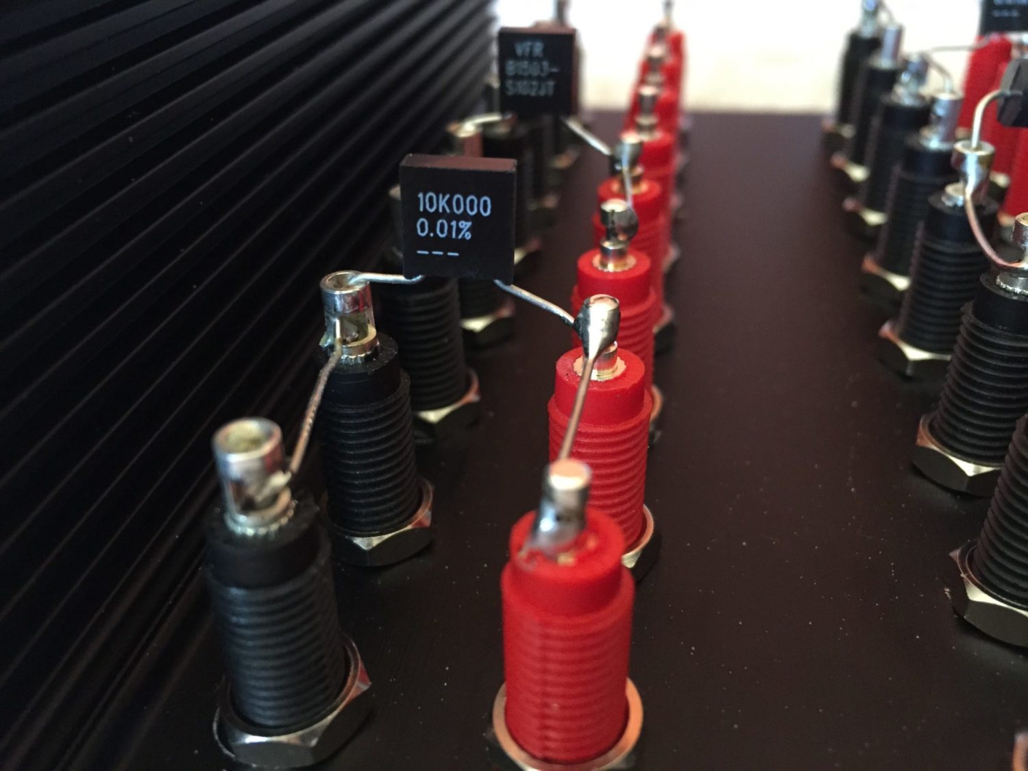
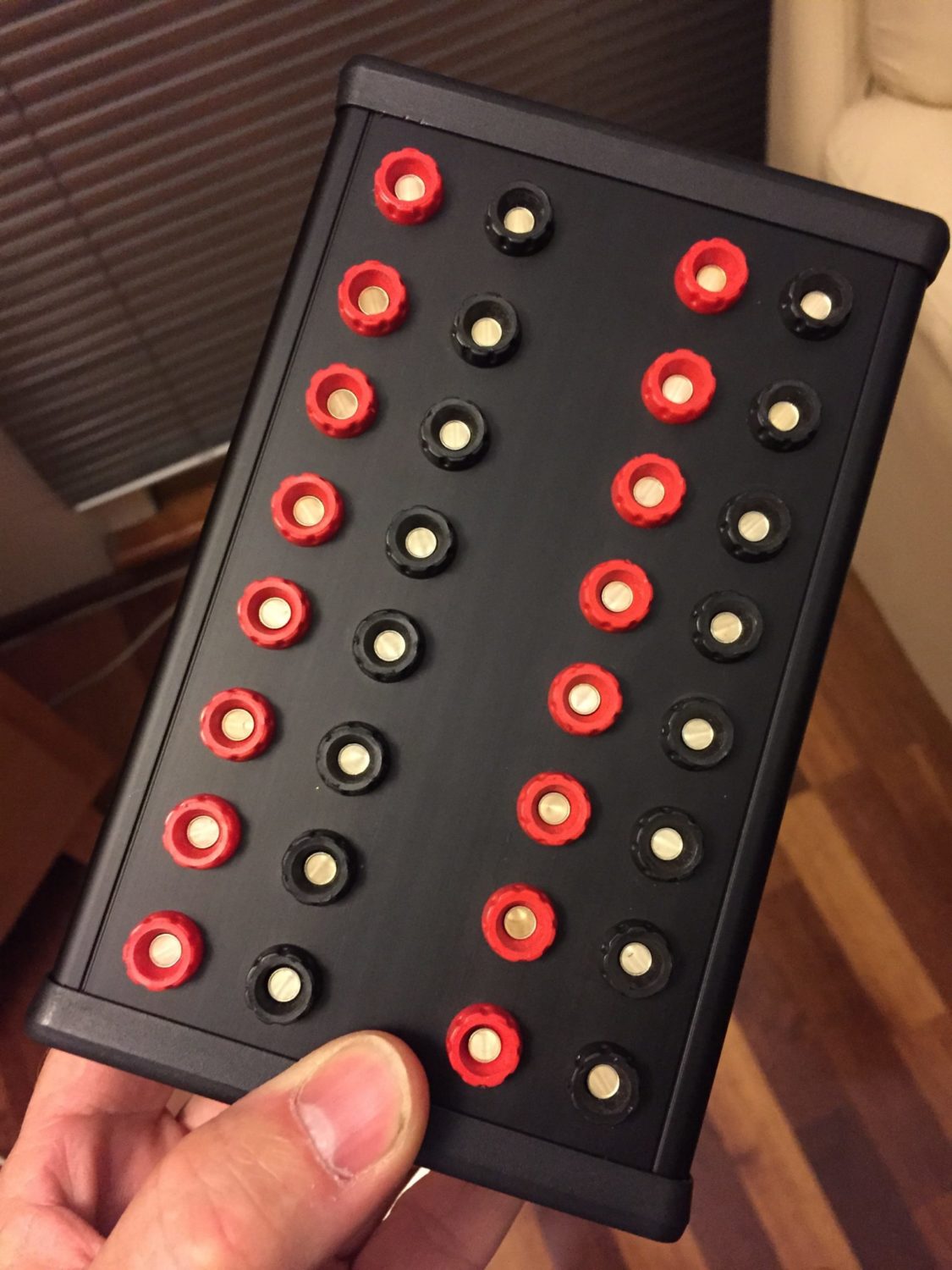
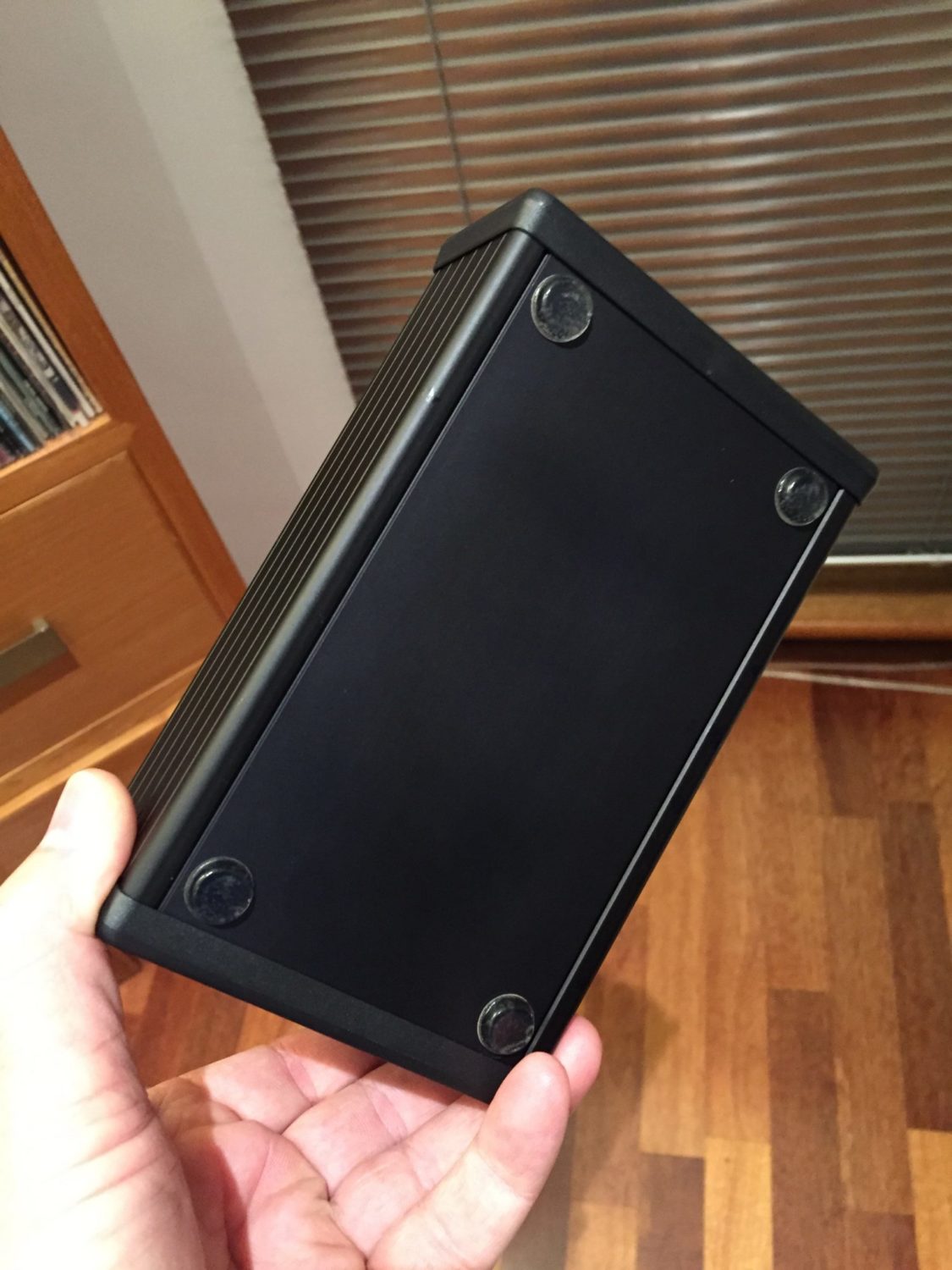
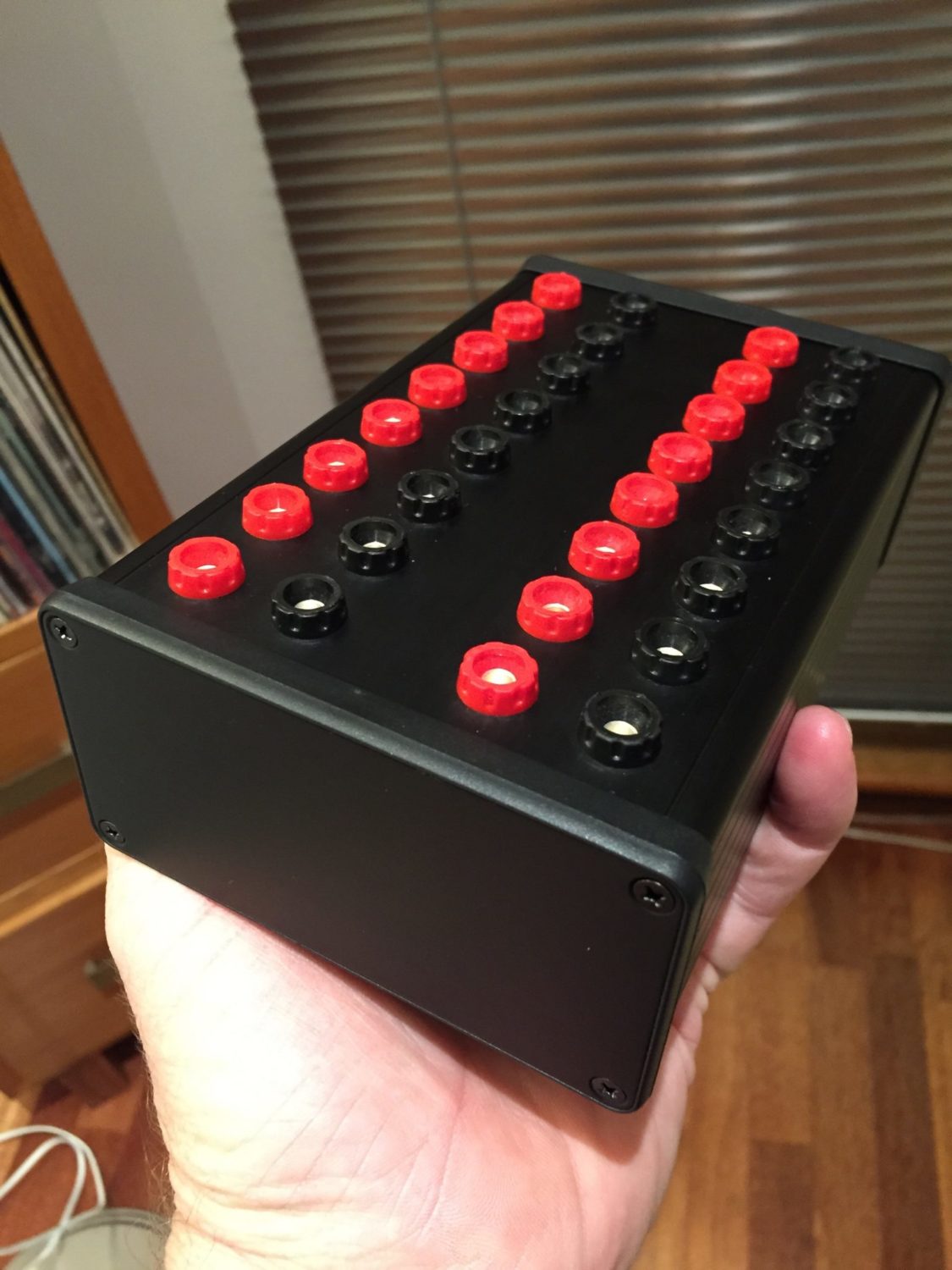
When designing the box layout, I decided to make 8 sets of four terminals available on the front panel. This meant I had room for a zero ohm resistance as well as the others I wanted in the box. The images below show most of my steps in making the standard. It’s turned out very well in fact. The repeatability is very noticeably better than with standard two-wire setups.
Discover more from LiQUiD AUDiO
Subscribe to get the latest posts sent to your email.


I left a comment earlier about Vishay resistors inside Transmille 3000RS
Hi Edward, yes you submitted hat through my site feedback portal, those comments don’t go anywhere except directly to me. This is the best way to leave visible feedback and get conversations happening. Lots of great high-precision resistors out there from quite a few different manufacturers. I’ve had great success with Vishay parts and they are found in lots of test gear I work on but there are lots of great alternatives out there! Cheers, Mike.