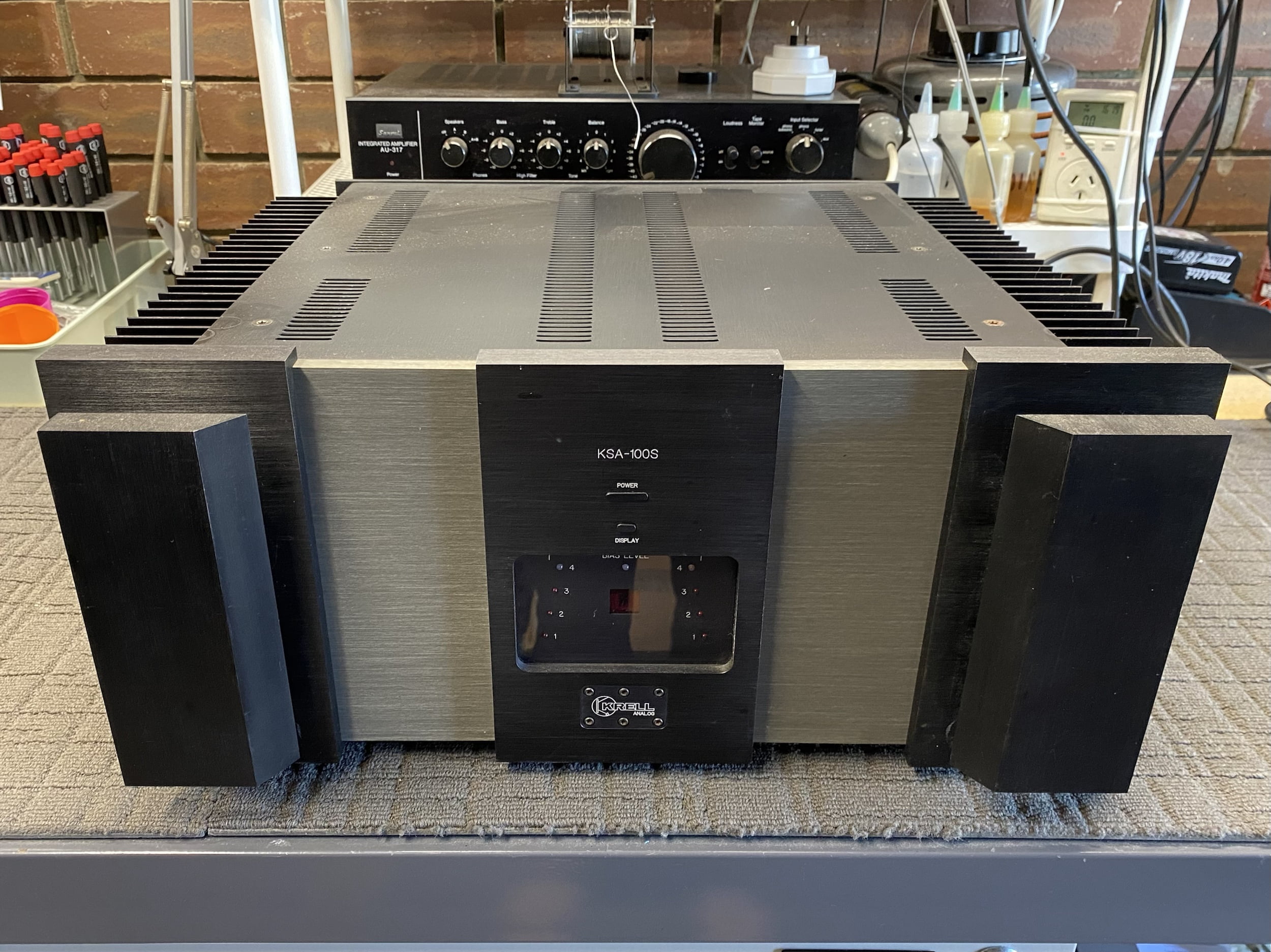
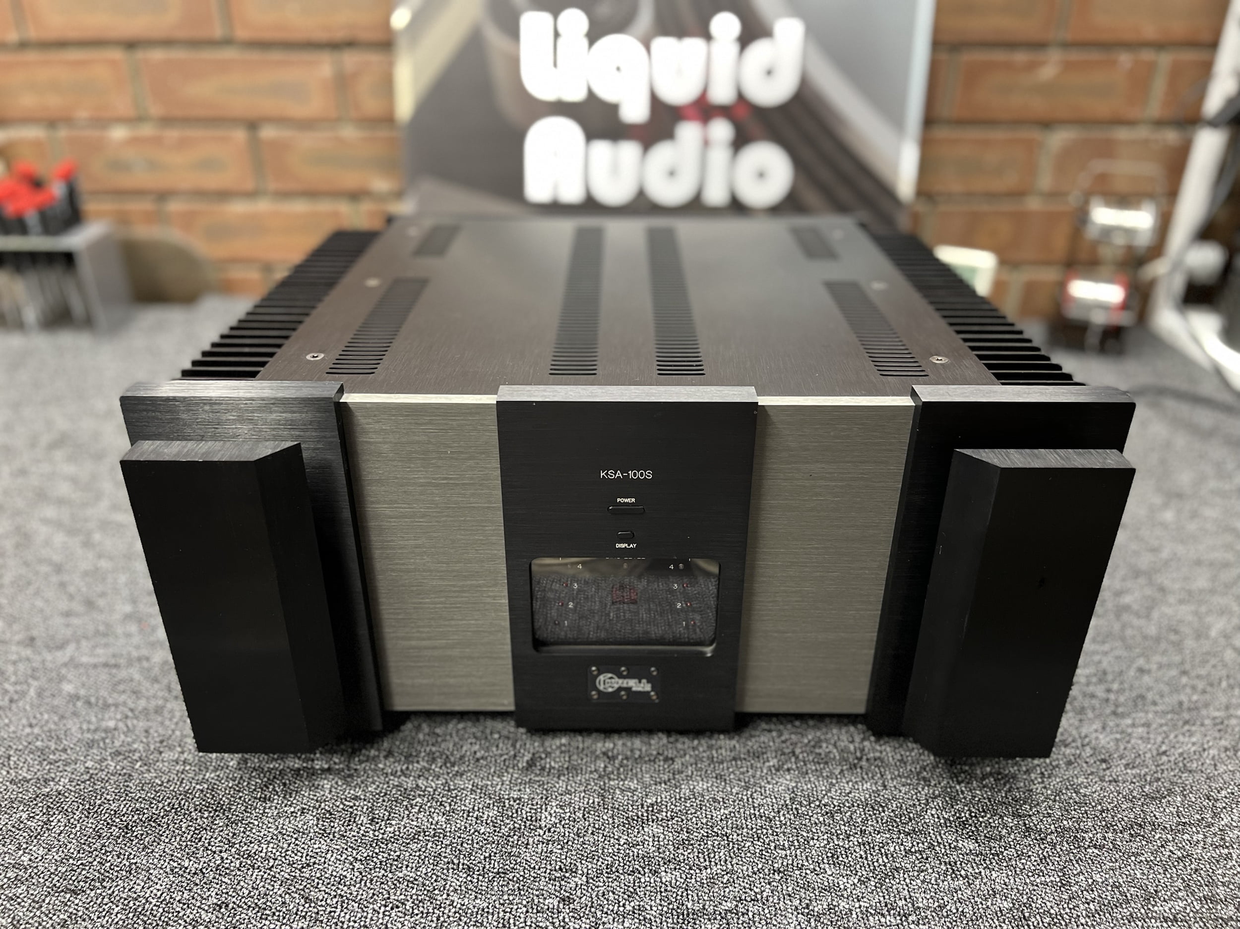
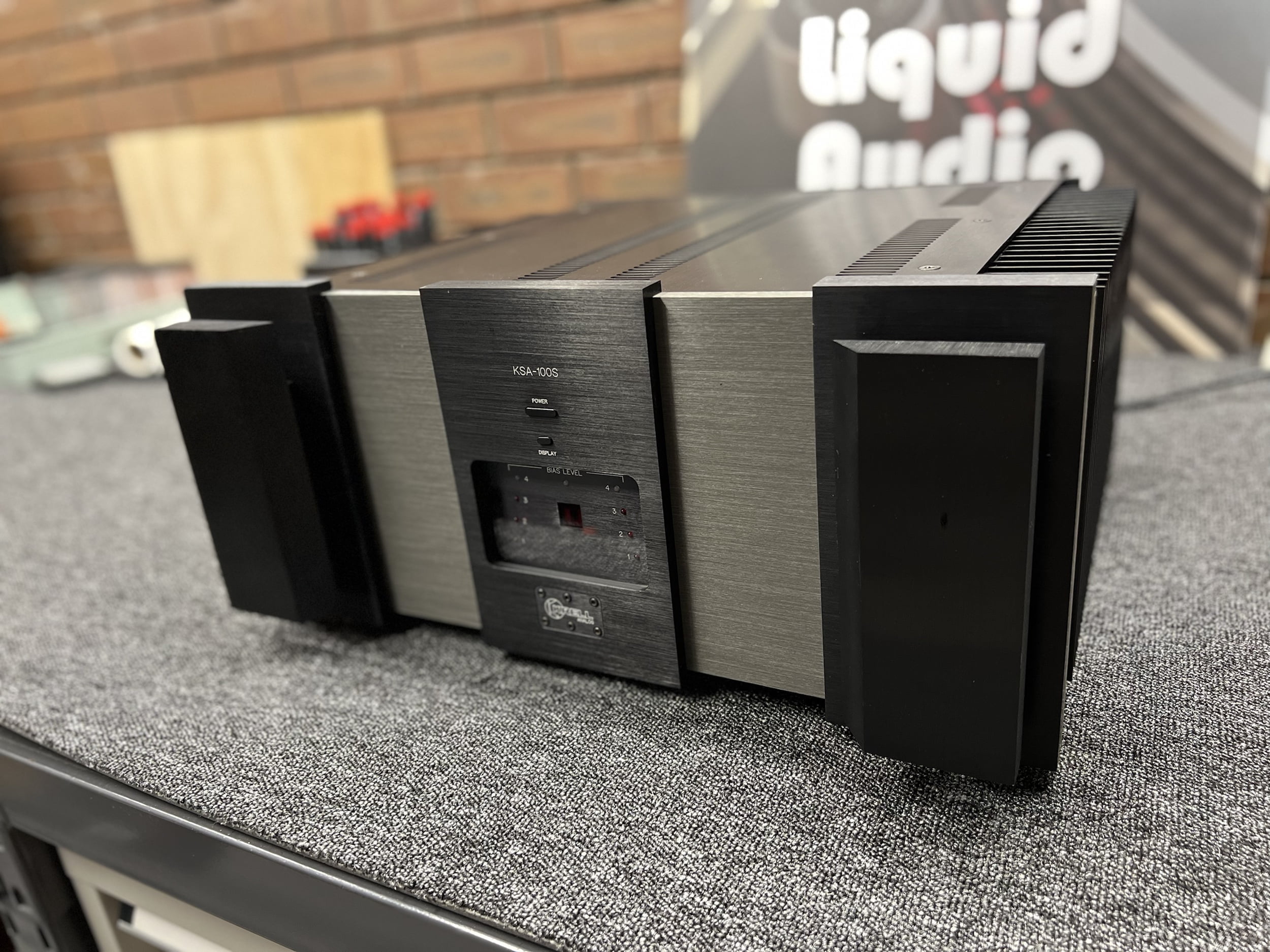
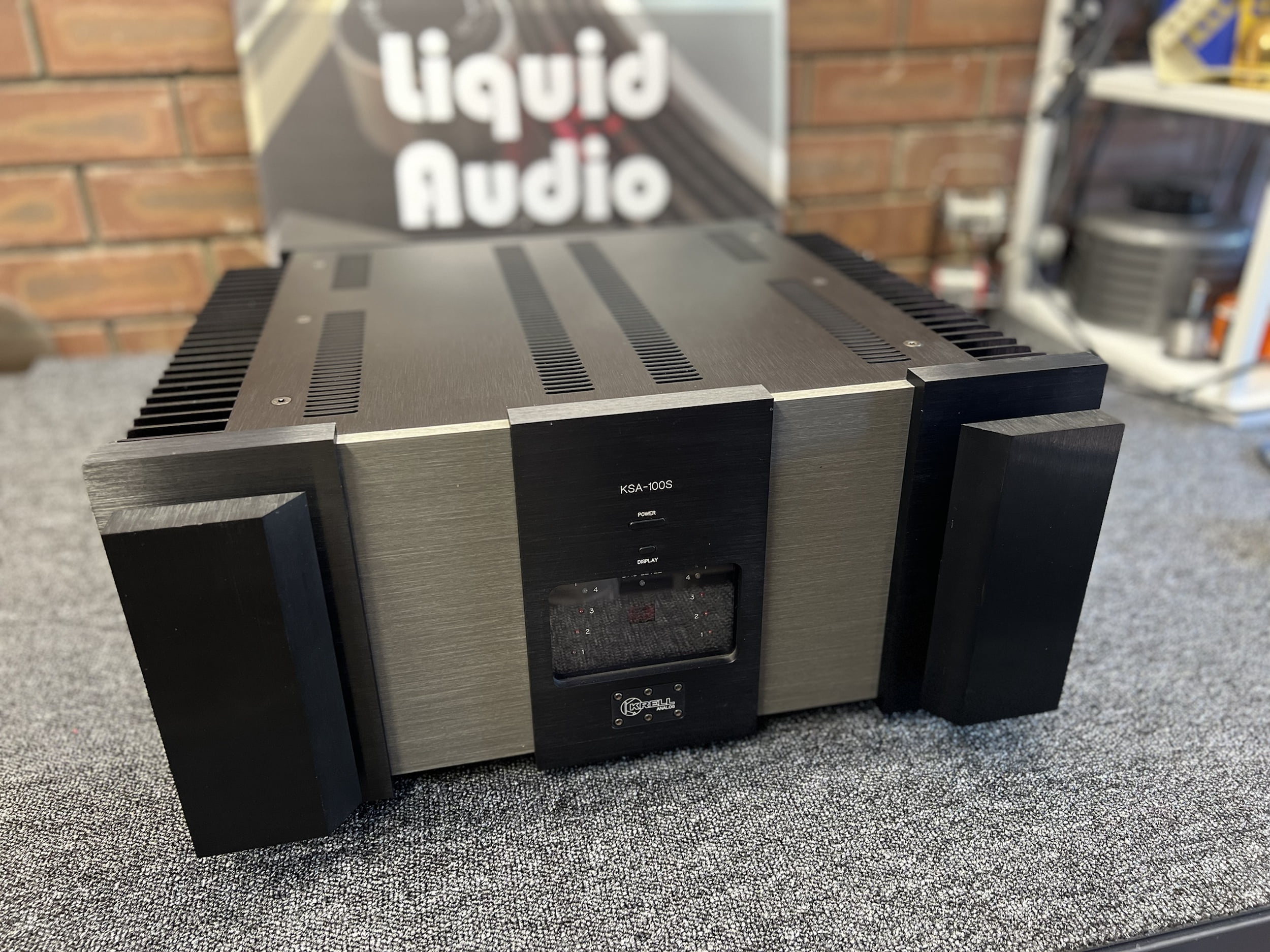
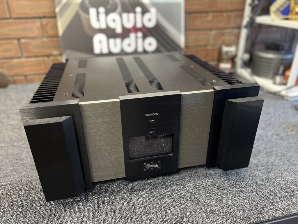
Good news, we’ve saved another stunning, irreplaceable amplifier, this time a Krell KSA-100S power amplifier from Krell’s golden era.
Welcome back, classic hi-fi lovers! If you like amplifiers you’ll enjoy this one. Almost nothing is built like this beautiful amplifier now or even back then. Gear like this stunning Krell KSA-100S is so hard to find and so horrendously expensive to replace that fixing it is almost always worth doing. Short of catching fire or being dropped through the roof after being stored in the loft (true story for another time), there’s almost nothing that would prevent an amplifier like this KSA-100S from being repaired.
Originality
Documenting the repair and restoration of a beast like this is another story. The diagnostic, disassembly, repair and restoration work involved in a job like this is significant. Documenting it and crafting it into an article is a massive undertaking, taking days rather than hours, which is why I don’t do it very often. There aren’t many others doing it either. There are no manuals for how to approach work like this and professionals rarely put pen to paper about it, for various reasons. As a result, we see a few copy-cats.
After posting this article, for example, someone calling themselves a repairer added his business details as a comment under the Liquid Audio Facebook post about the job. He claimed he “did the same work”, attempting to use our work to boost his business. I deleted his post and, whilst I’m flattered that others would claim to do the same work, whatever that means, nobody works quite like I do, nor do work quite like anyone else, if you get me. This is to be expected.
I think it’s important that people see what’s involved in a job like this. There are dozens and dozens of big projects like this waiting for me to turn into stories. I don’t have the time to write them, we’re doing it this time though. Let’s go!
Krell KSA-100S Specifications
Courtesy of Stereophile
Power output: 100W/Ch into 8 Ohms (20dBW), doubling with each halving of load down to 800W into 1 Ohm
Frequency response: 20Hz–20kHz, +0.0/– .1dB; 1Hz–150kHz, +0.0/–3dB
Distortion: <0.1% at 1kHz; <0.5%, 20kHz, full power
Slew rate: 100V/µs.
Input sensitivity: 1.4V RMS
Gain: 26dB
Damping factor: >60
Input impedance: 47kOhms
Power consumption: 100W, idle; 1400W, full power (oh yeah!)
Dimensions: 19″ W by 8.5″ H by 19.25″ D.
Weight: 80 lbs / 36kg
Price: $5500USD (1994); no longer available (2007)
Background
You can read more about this amplifier in a great Stereophile review from the time. The S Series, of which the KSA-100S is a part, came after the non-S series, of which my old KSA-150 was a part. Now, these non-S amplifiers were a true class-A design, (well, up to a point) with no sliding bias and dissipated much more power at idle as a result. I would argue they sound better too, but the S series models like this KSA-100S are easier to live with day-to-day due to their more modest power consumption.
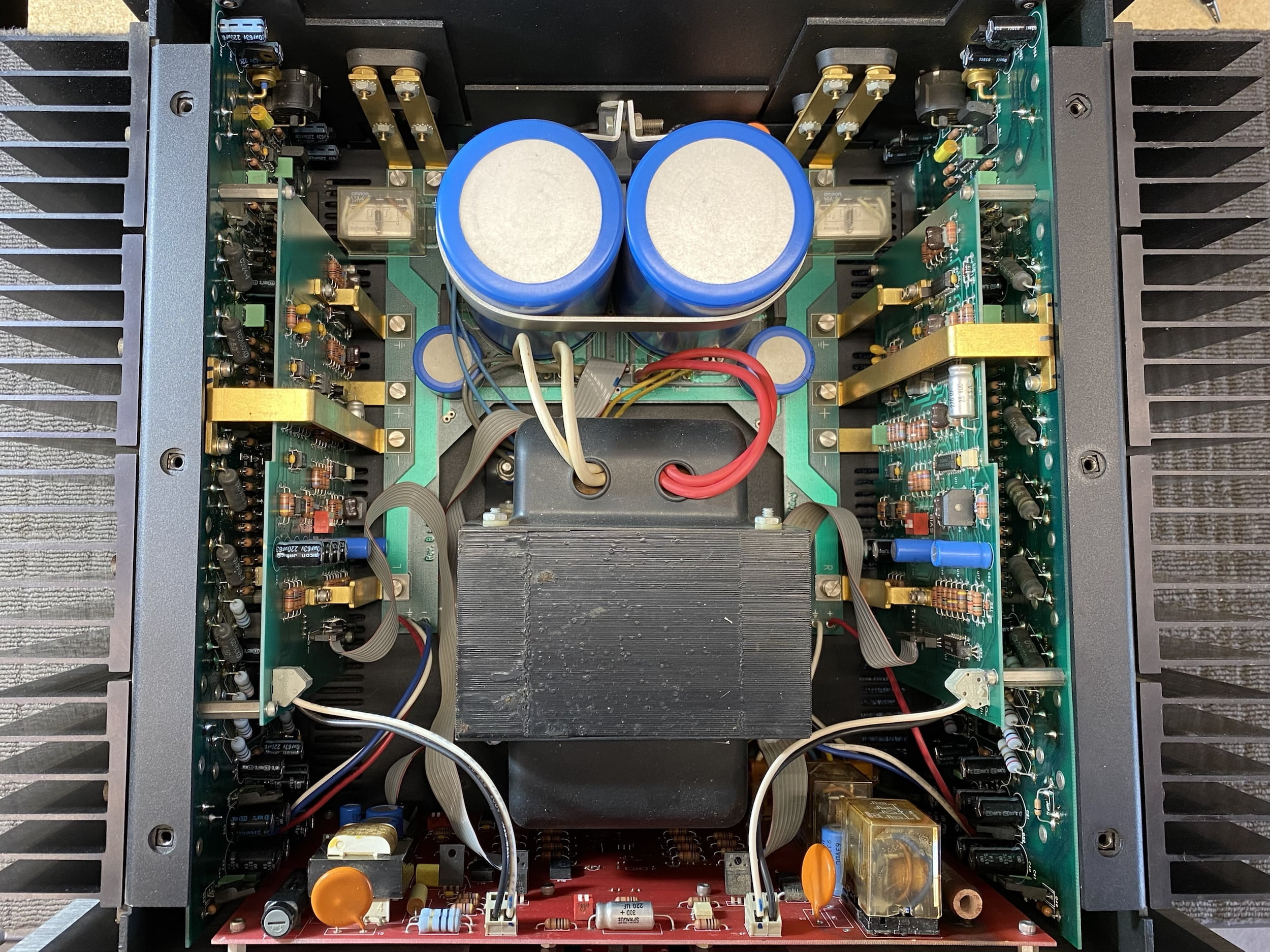
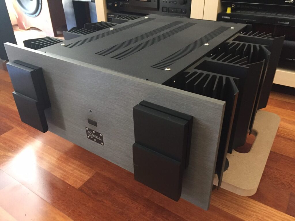
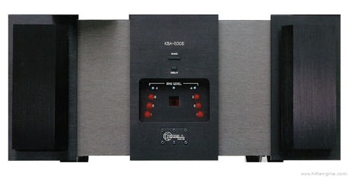
Released around 1994, there were various ‘S’ series models including the KSA-100S, KSA-200S (mega rebuild article coming soon) and KSA-300S. This is the daddy and a stupid-heavy monolith that impresses the hell out of me whenever I see one.
These amplifiers are very impressive, featuring all of the Krell hallmarks of the time: next-to-no wiring, crazy good build quality, amazing performance, of course, and stunning looks.
Problems
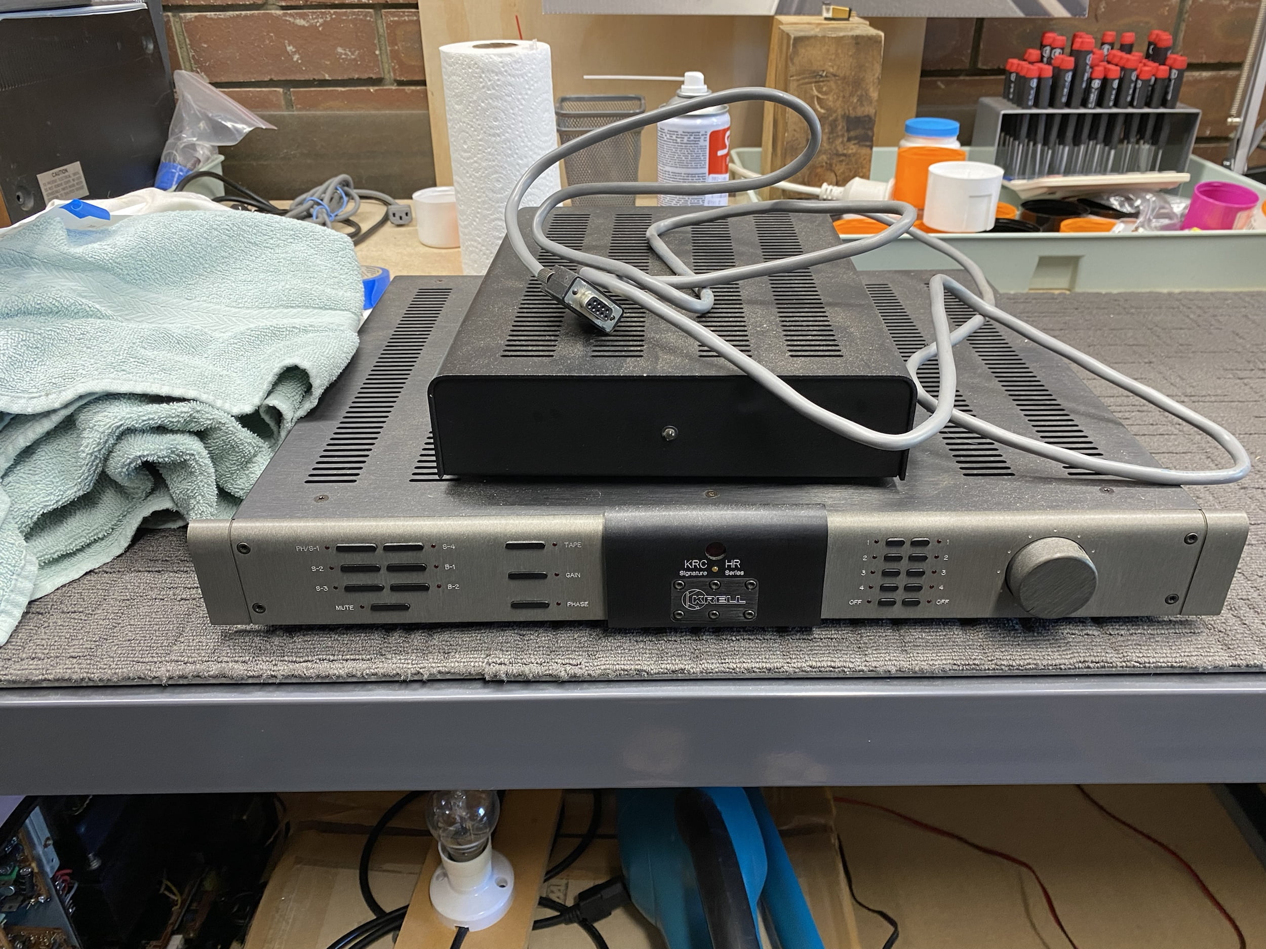
This Krell KSA-100S came to me at the same time as the matching Krell KRC-HR preamp which I also repaired and overhauled, more on that in another article. I did overhaul this Krell KRC-HR though for another customer, so take a look at that for background.
This Krell KSA-100S had released a large puff of magic smoke in a moment that startled her owner and signalled the end of normal operations, for a time. She’d blown various hard-to-access parts, as well as harbouring a dirty little secret in her power supply that kept her from powering on after the initial and extensive repair and restoration work.
My apologies again to her lovely owner for that period being so long. Unfortunately, this amplifier came to me at a busy time and had several different and unrelated issues, all of which had to be resolved before I could give her back. An amplifier like this, needs time, space and return time to diagnose additional issues and make further repairs in between other pressing jobs.
So what are those issues?
- Magic smoke from output device failure in the right channel
- Front control module relay and board heat damage
- A high-current power supply rail was absent
- The unit had suffered shipping damage at some point
This Krell KSA-100S had been previously repaired, though not in the way I would do it, likely leading to this failure now. Without further ado, let’s get straight into the repair and restoration process.
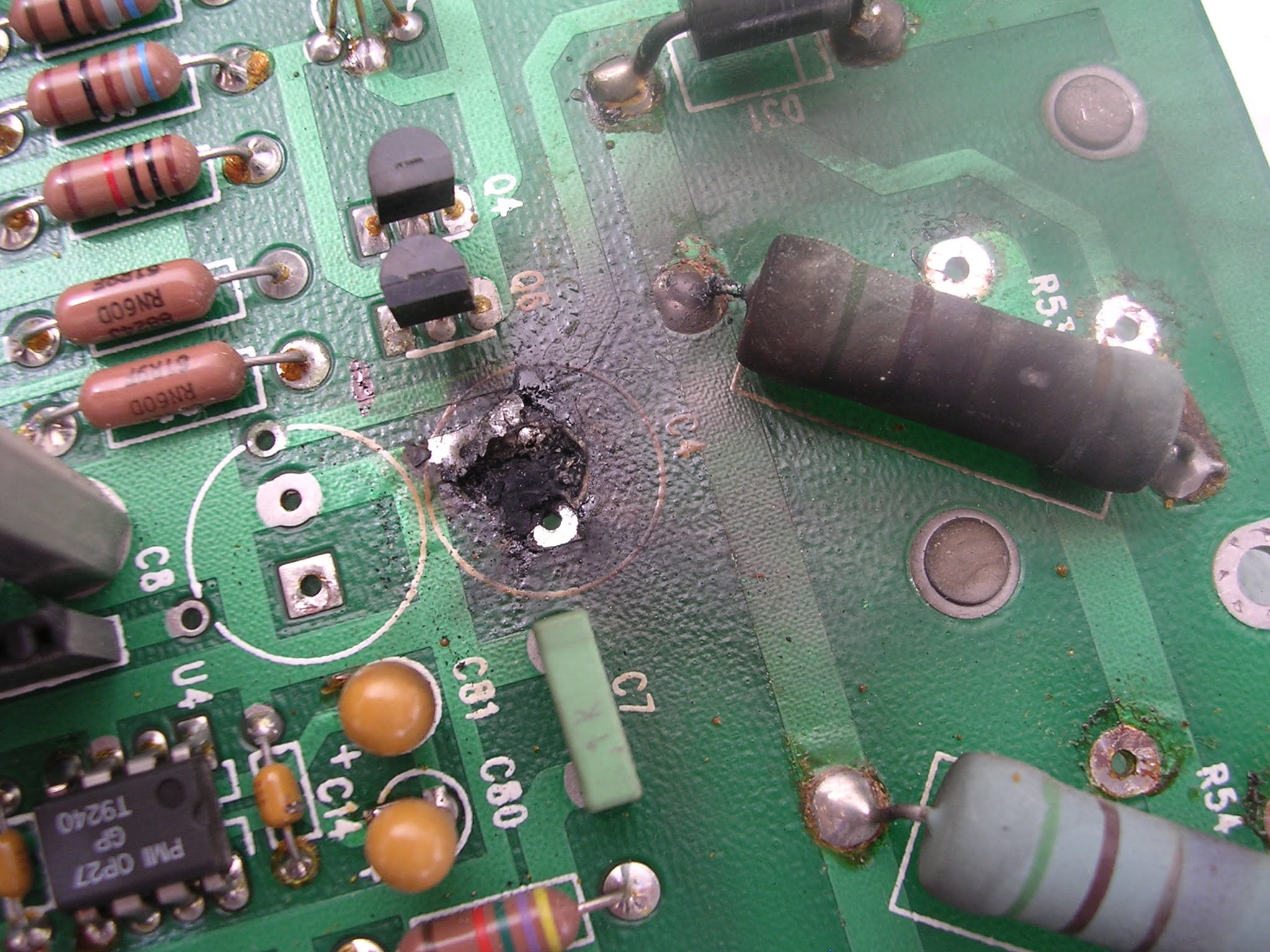
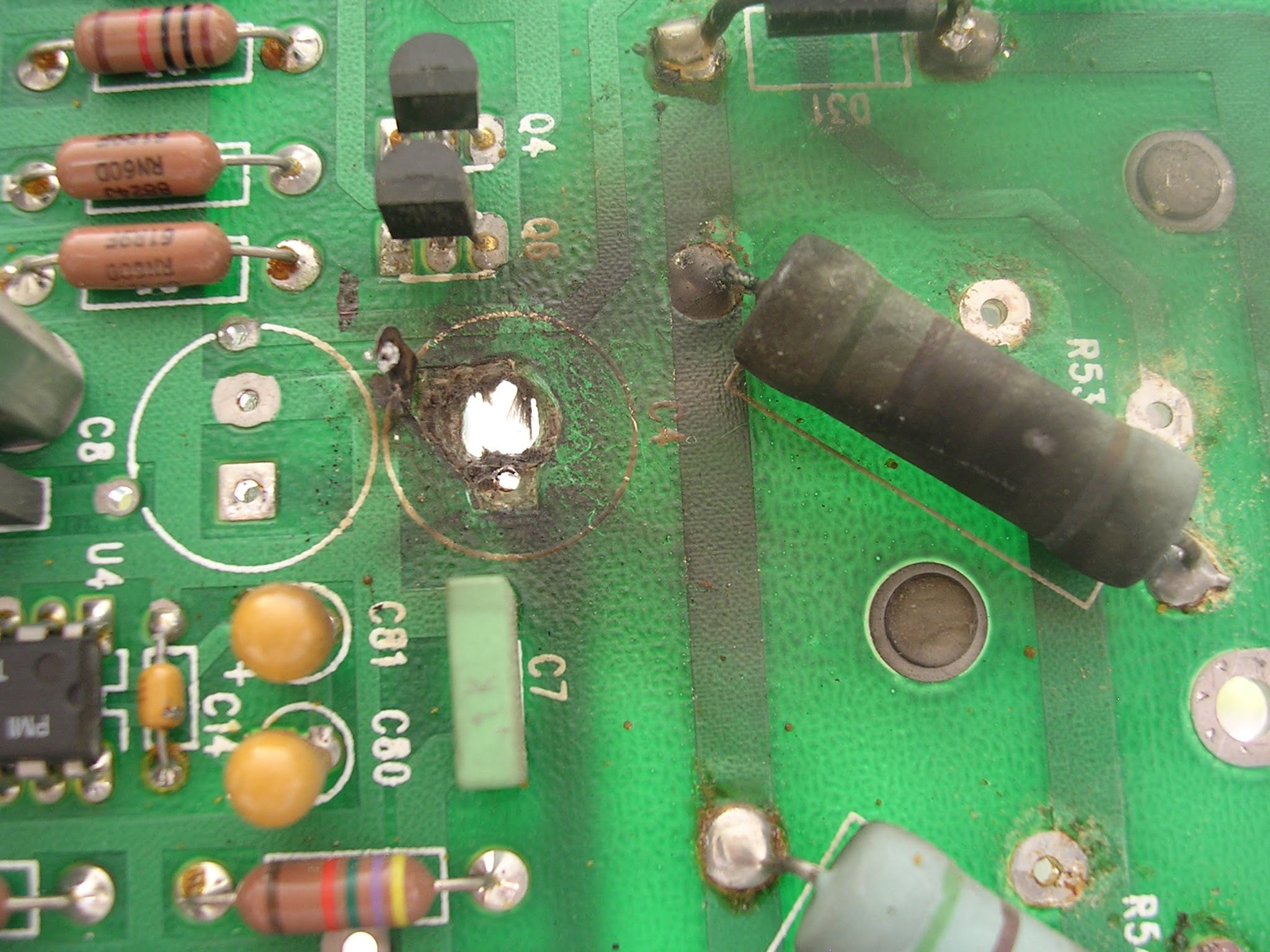
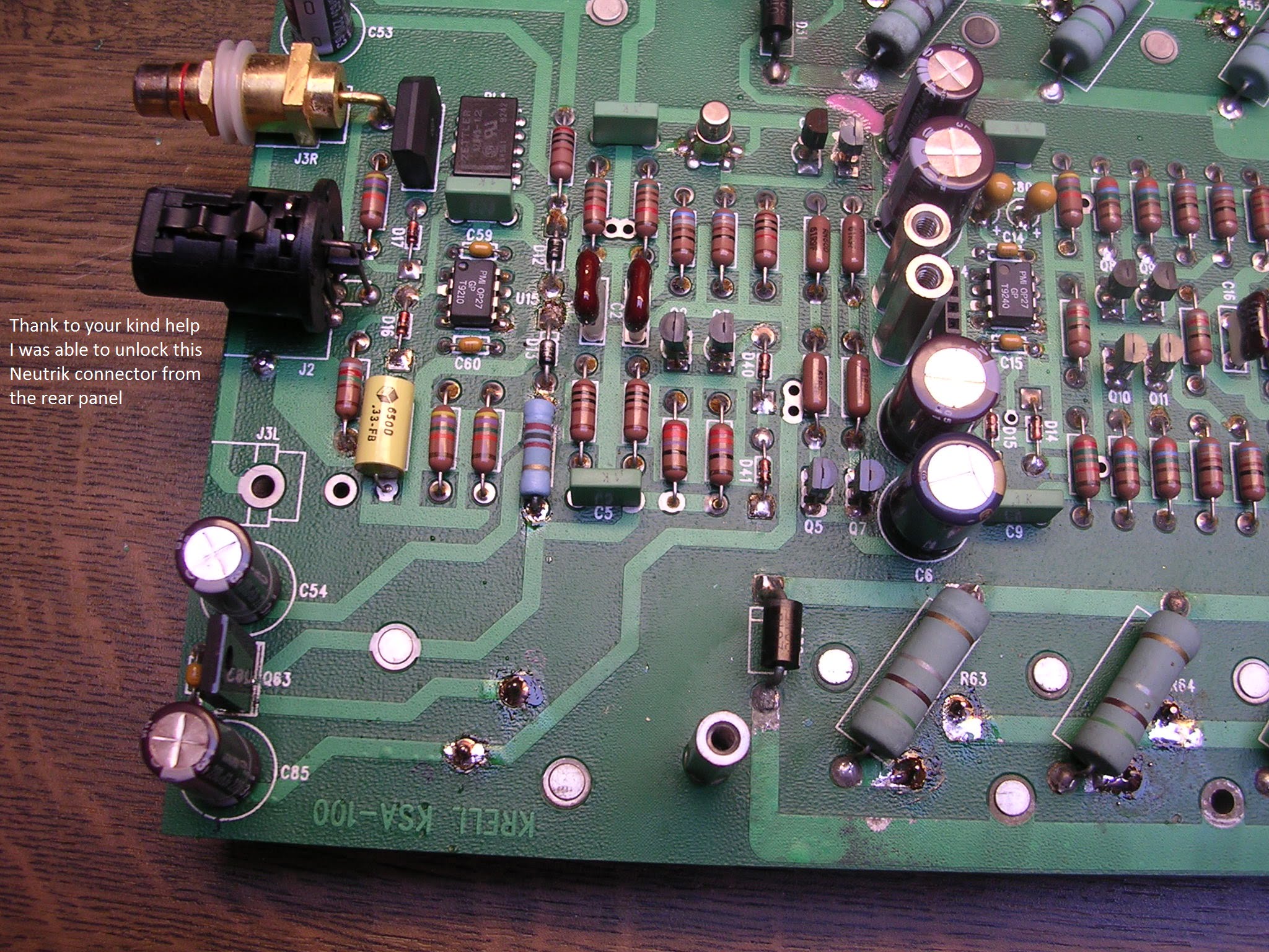
PS – before we get onto this repair, Vincent, one of my readers from France who contacted me regarding his own KSA-100S needing repair sent me these pics of one of the boards where a capacitor literally exploded, blowing a hole through the fibreglass substrate. Crazy!
Repair and Restoration
There were two goals with this Krell KSA-100S:
- Repair all known faults
- Restore her to provide many more years of trouble-free enjoyment
Note: This is commercial work and there are budgetary considerations. Replacing everything would be preposterously expensive, wasteful and stupid and not what this customer requested!
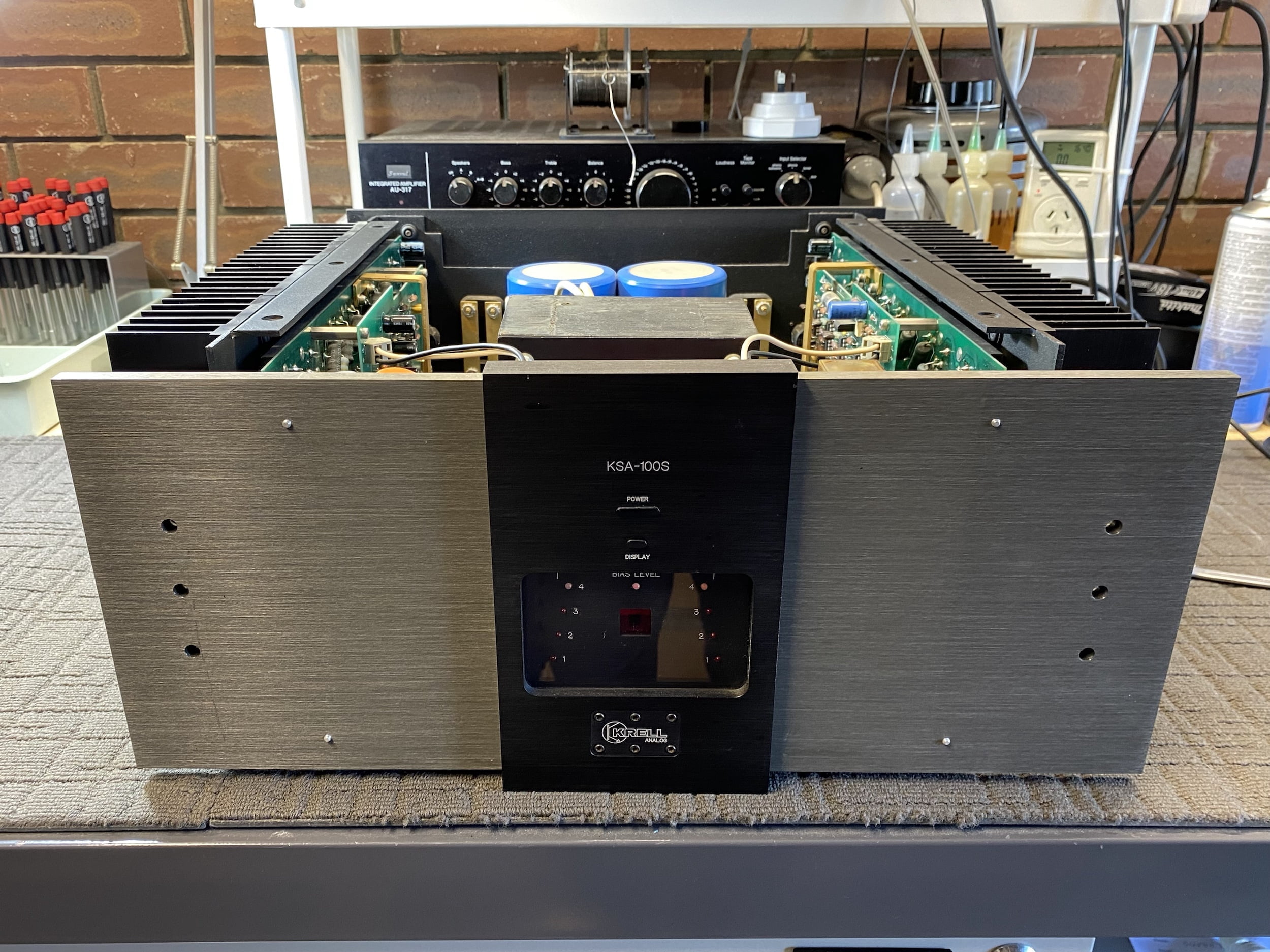
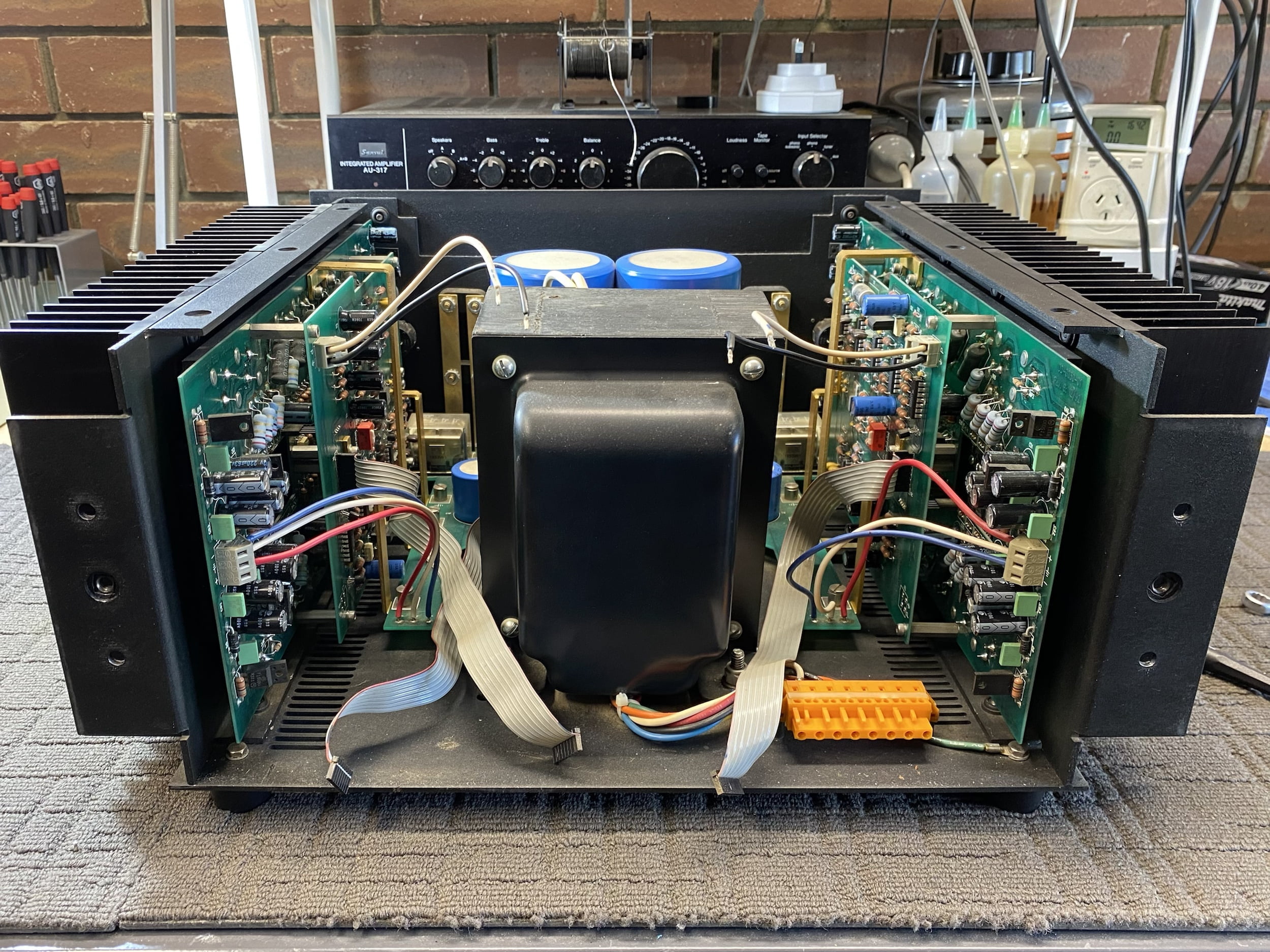
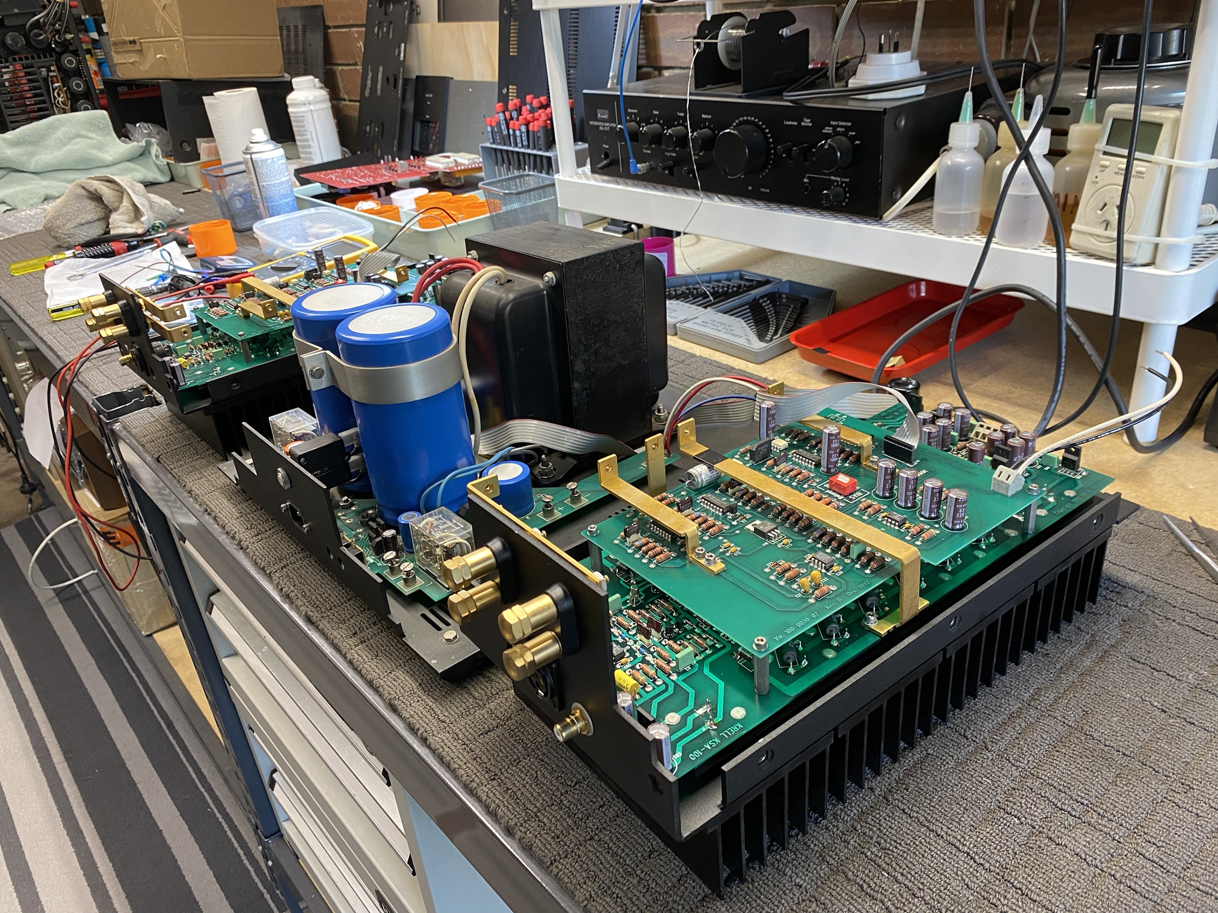
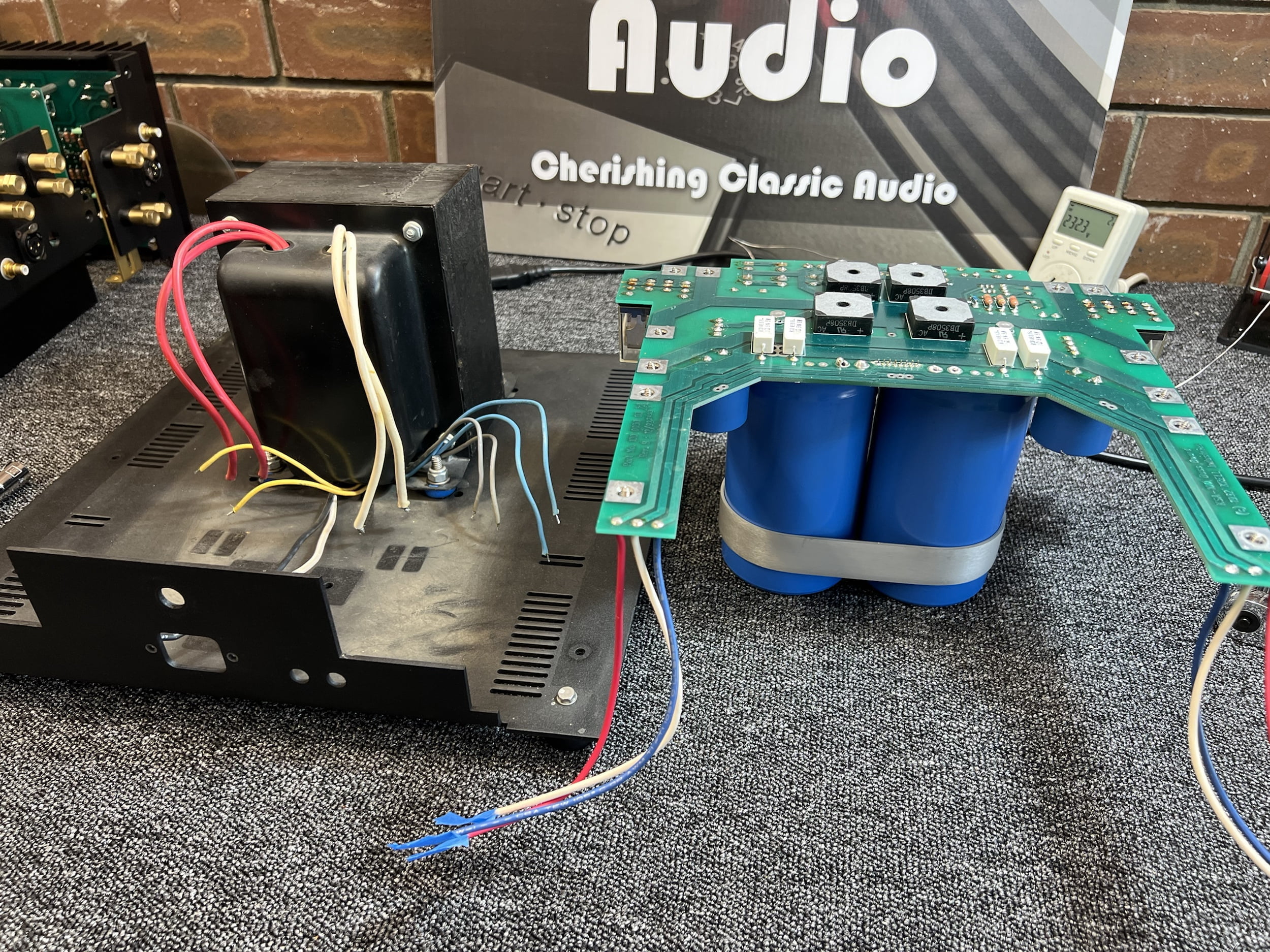
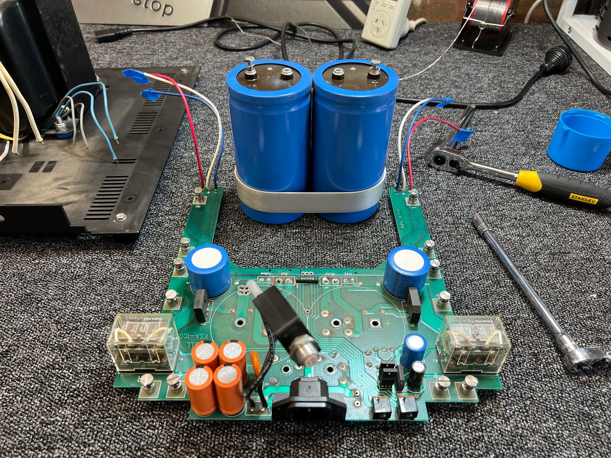
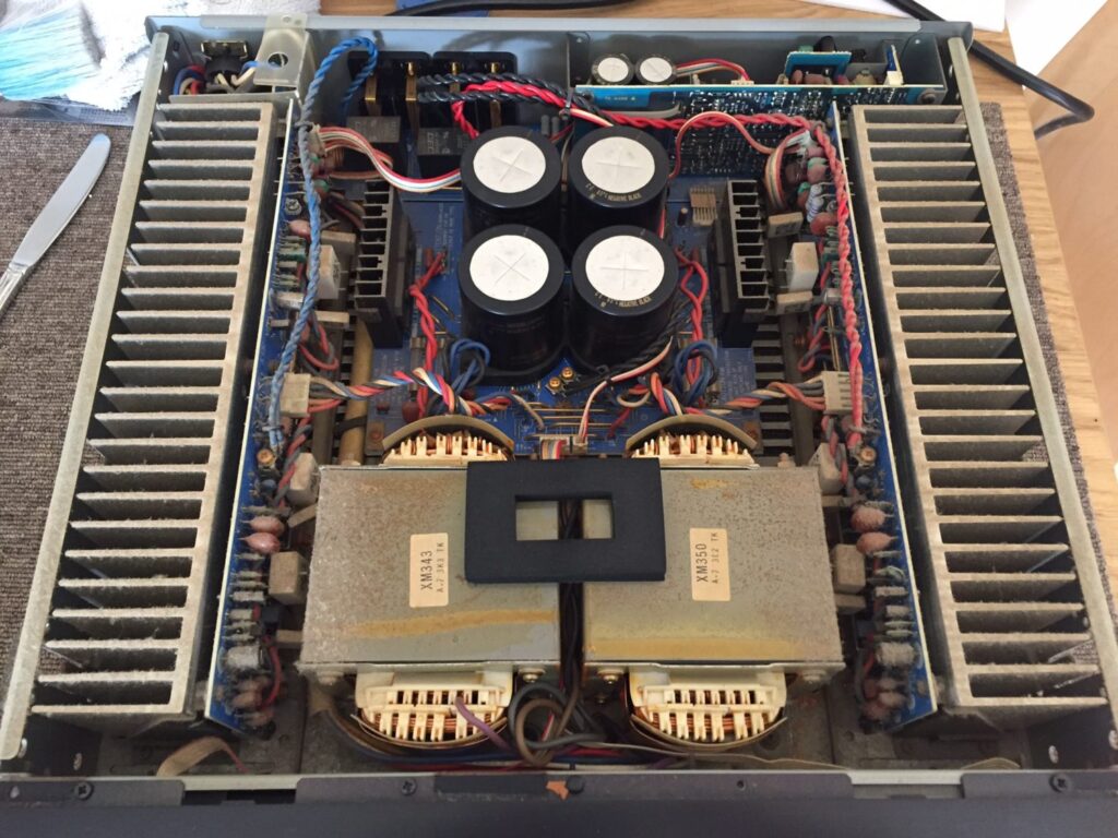
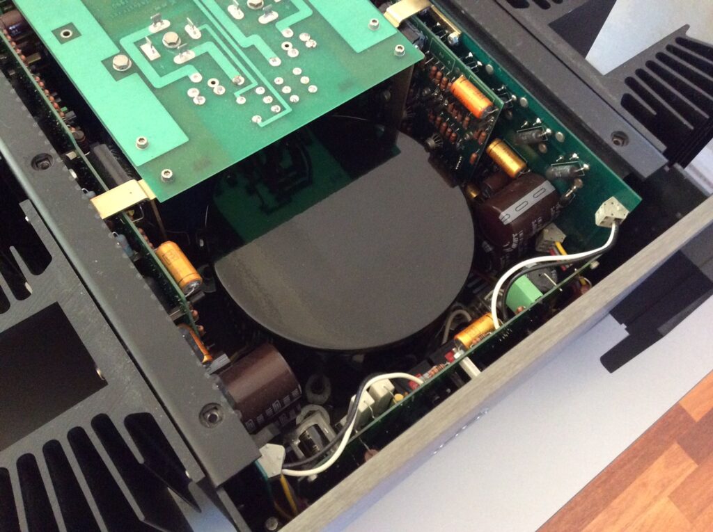
Initial work involved a thorough visual inspection and then disassembly, separating the amplifier into its modules so that each could be repaired and restored in turn. I’ll take you through that process, looking at the work we did on each of the amplifier modules: the control board, left and right amplifier modules and power supply module.
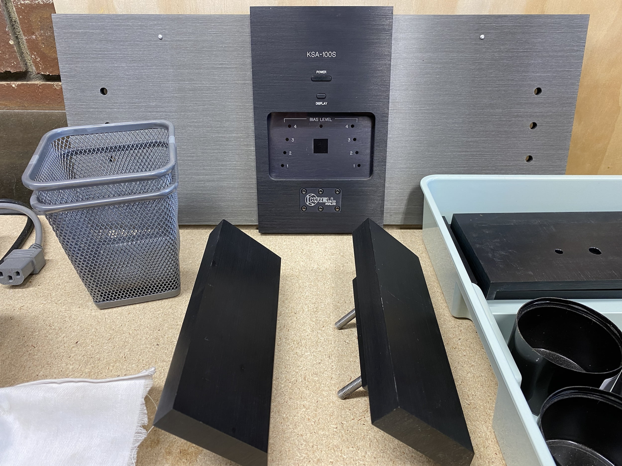
Amplifier Modules
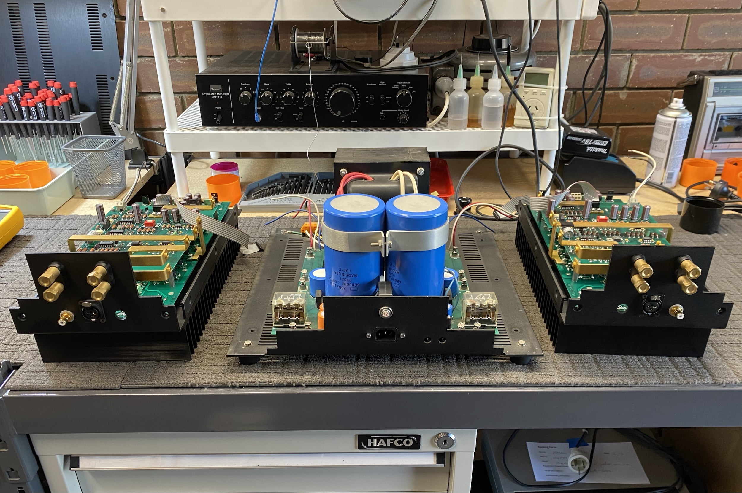
There are two of these of course so we start by removing the front panel and then the two amplifier modules. I’ll provide the most detail on the damaged channel.
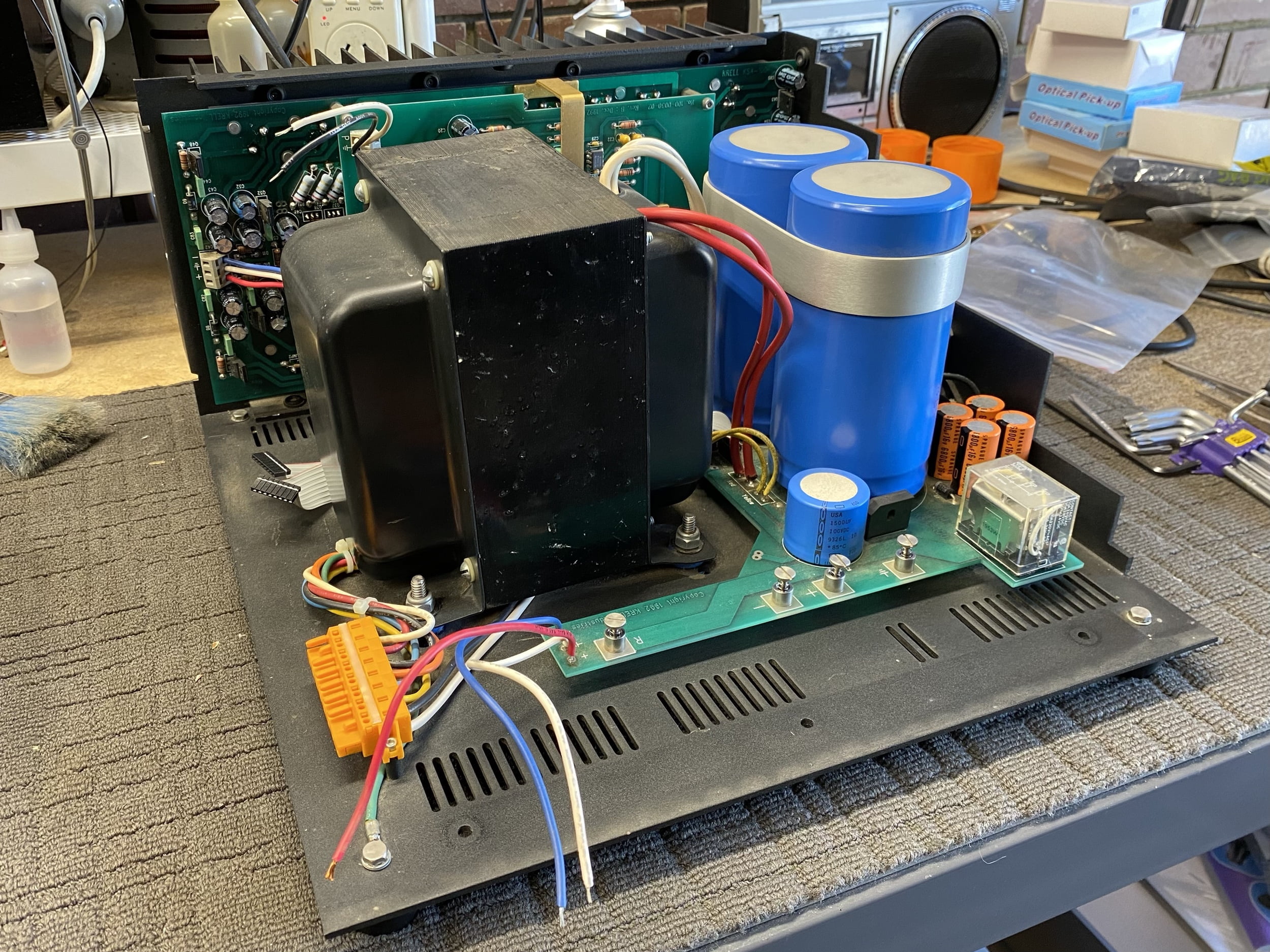
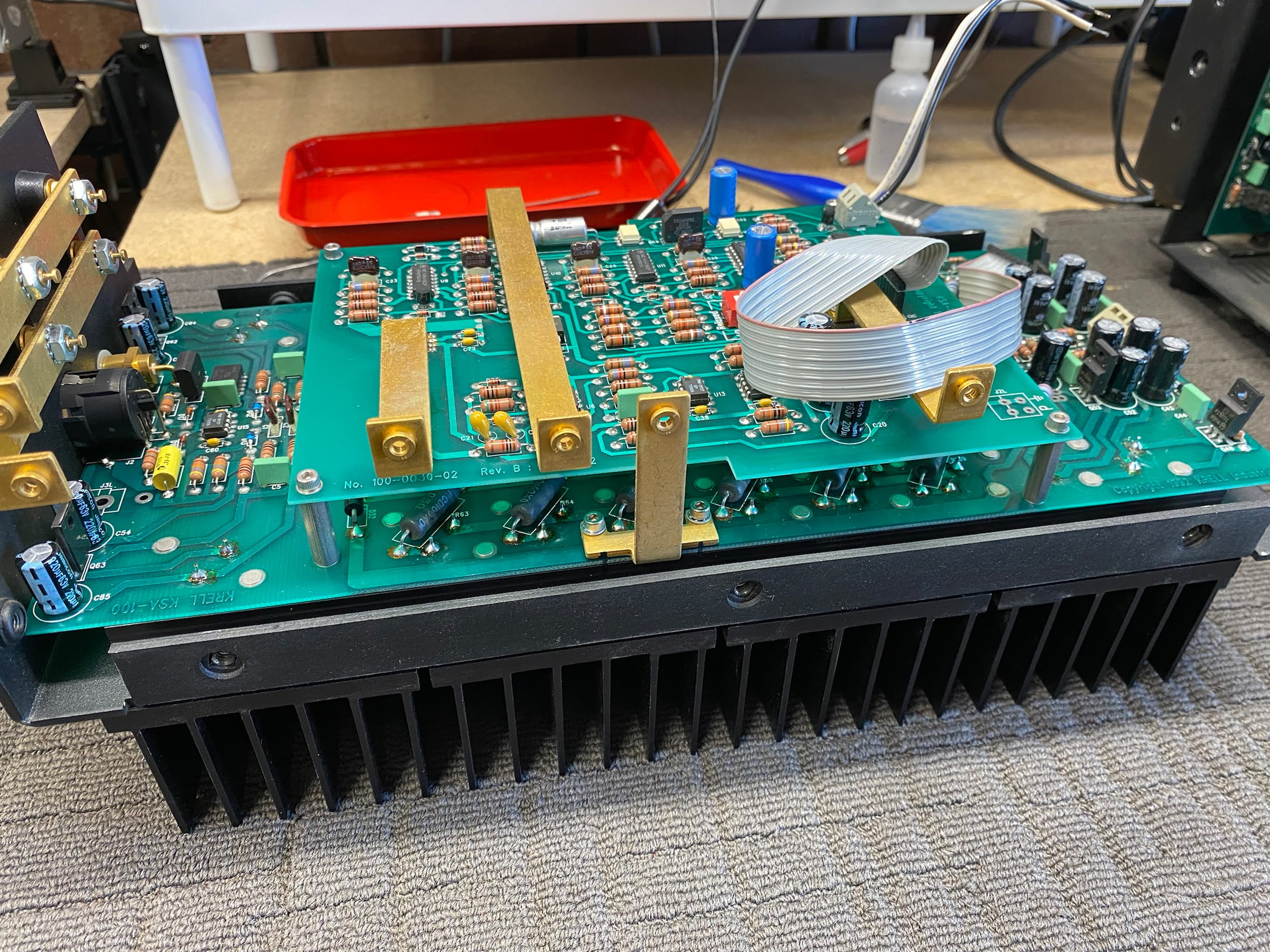
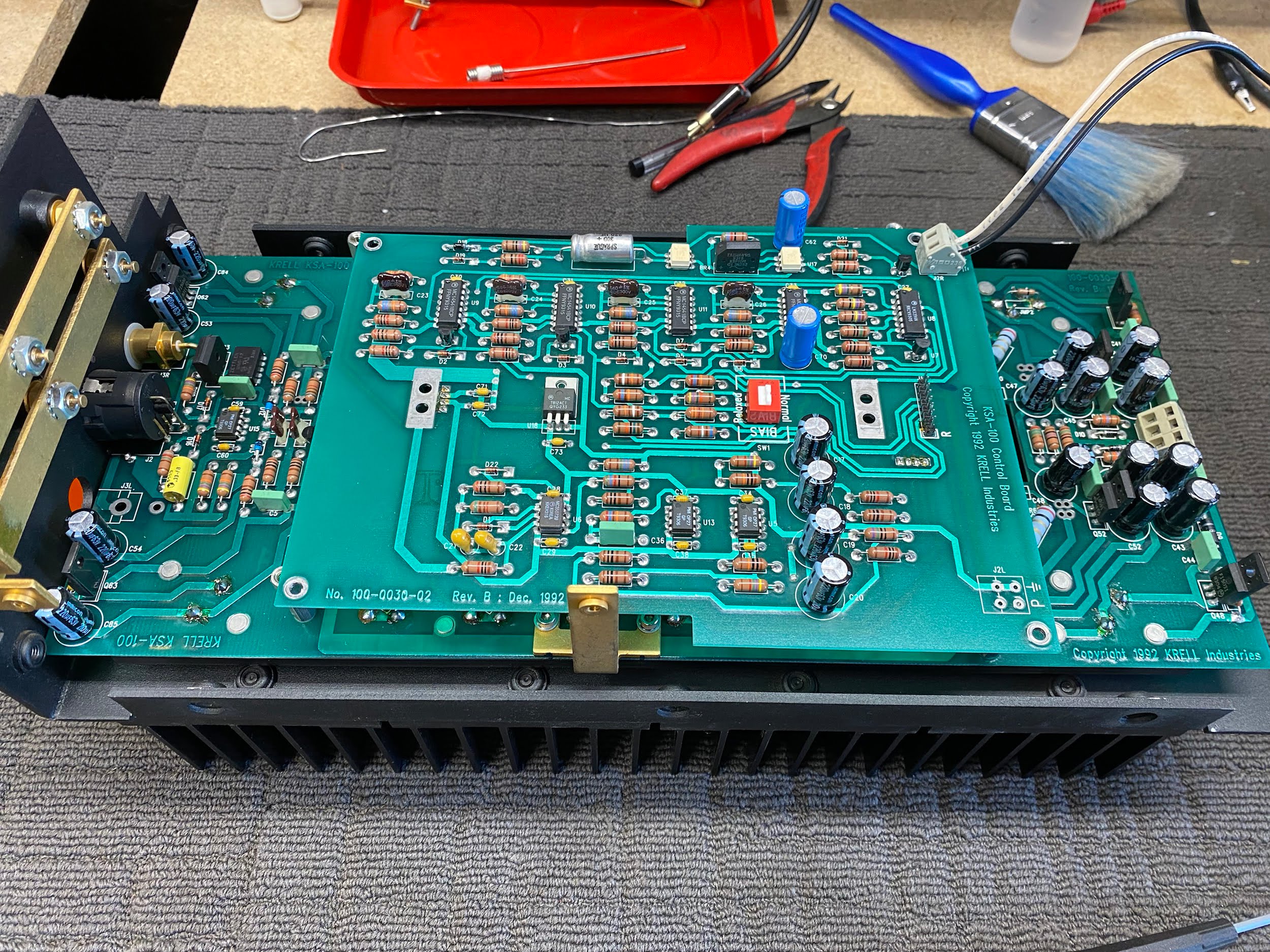
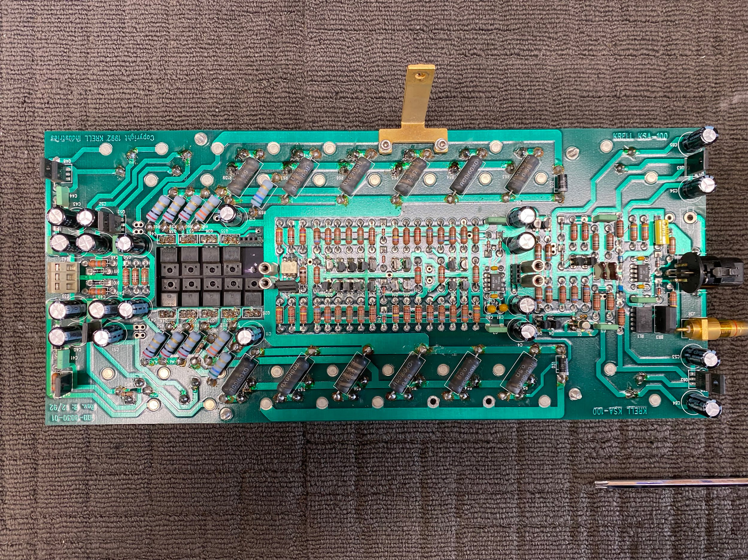
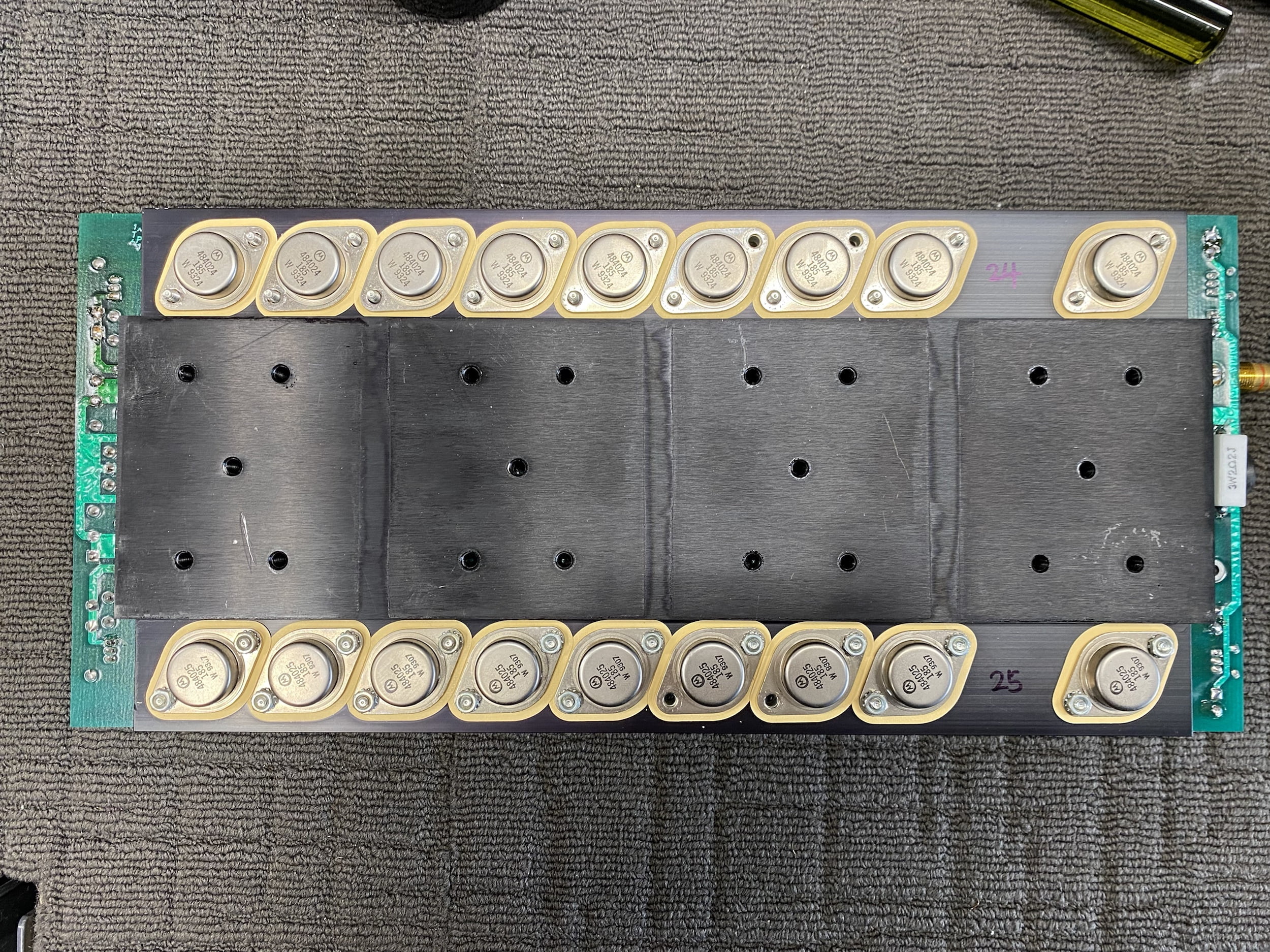
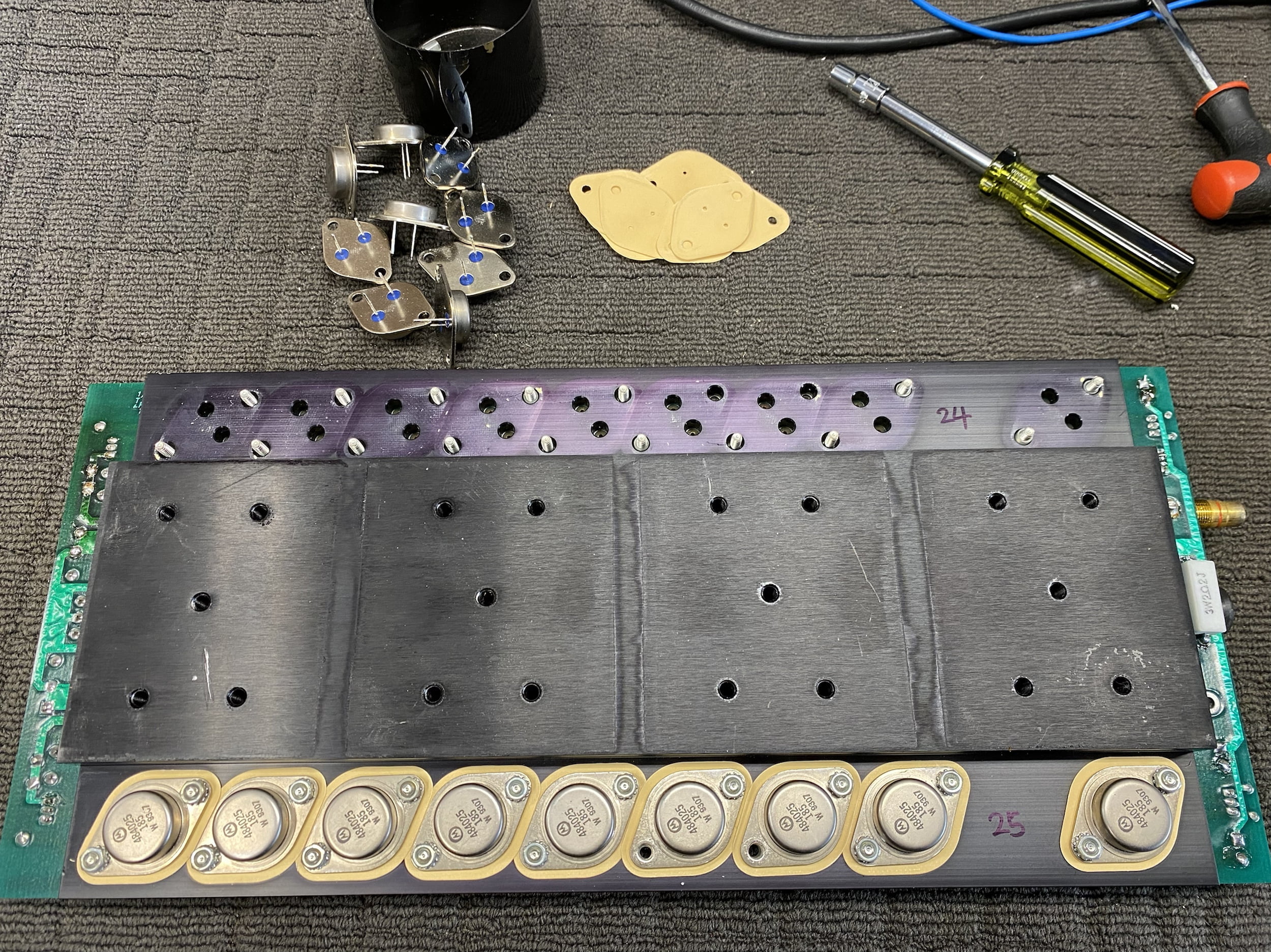
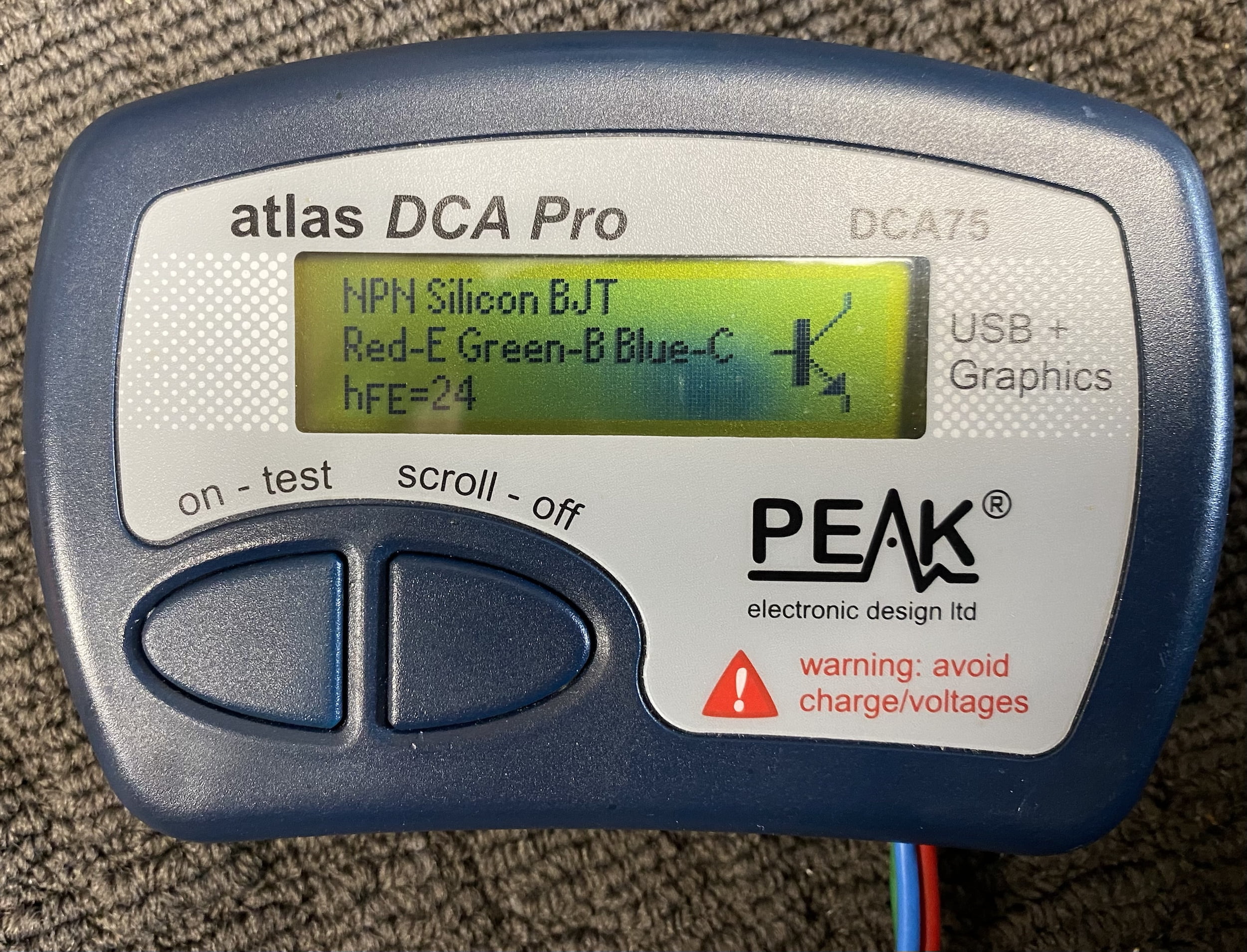
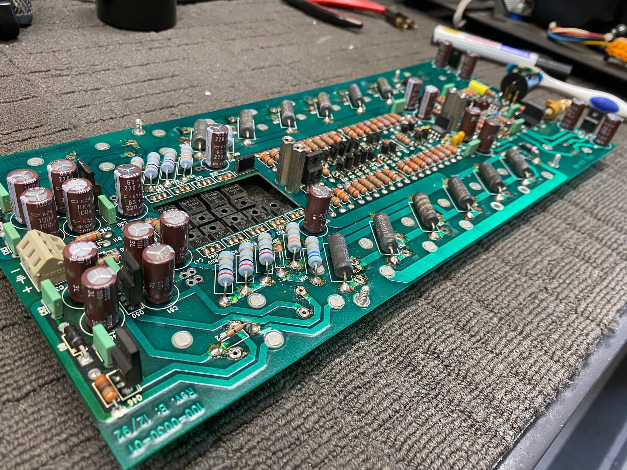
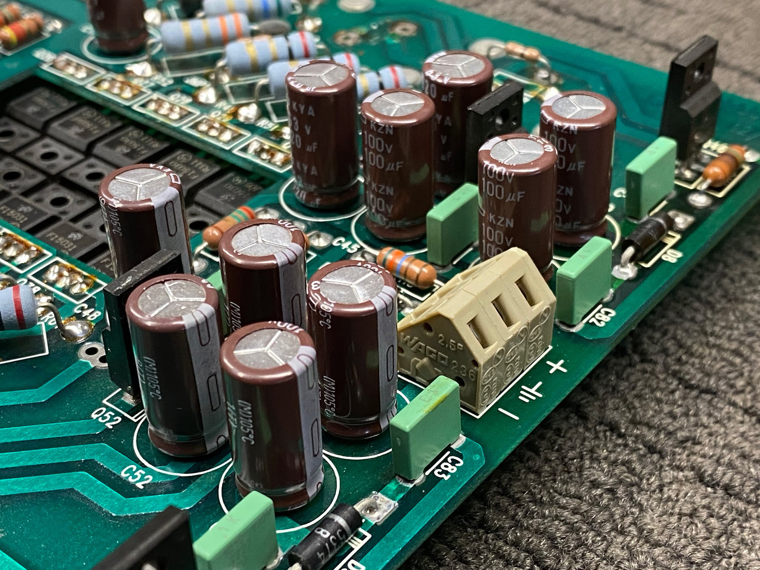
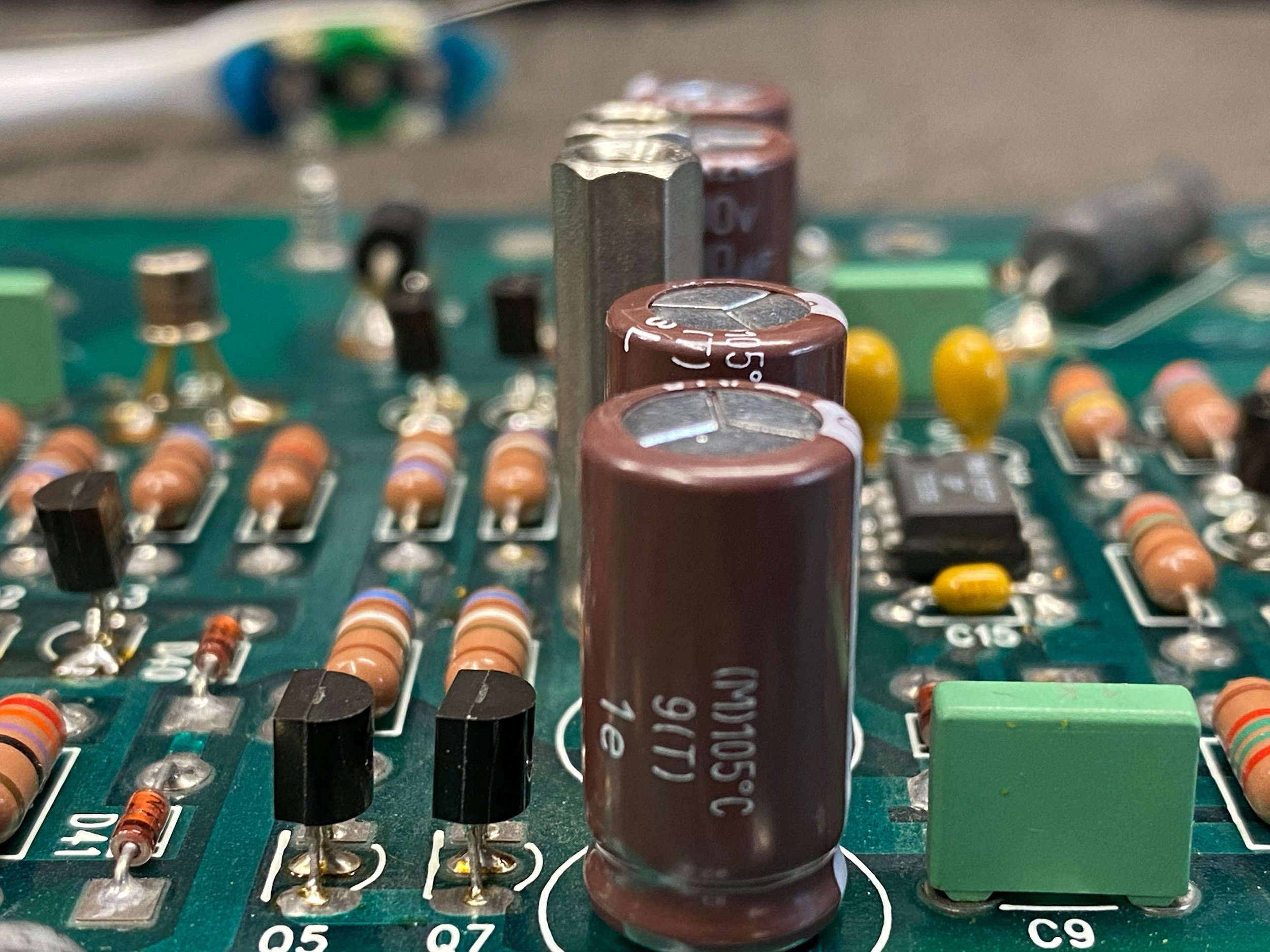
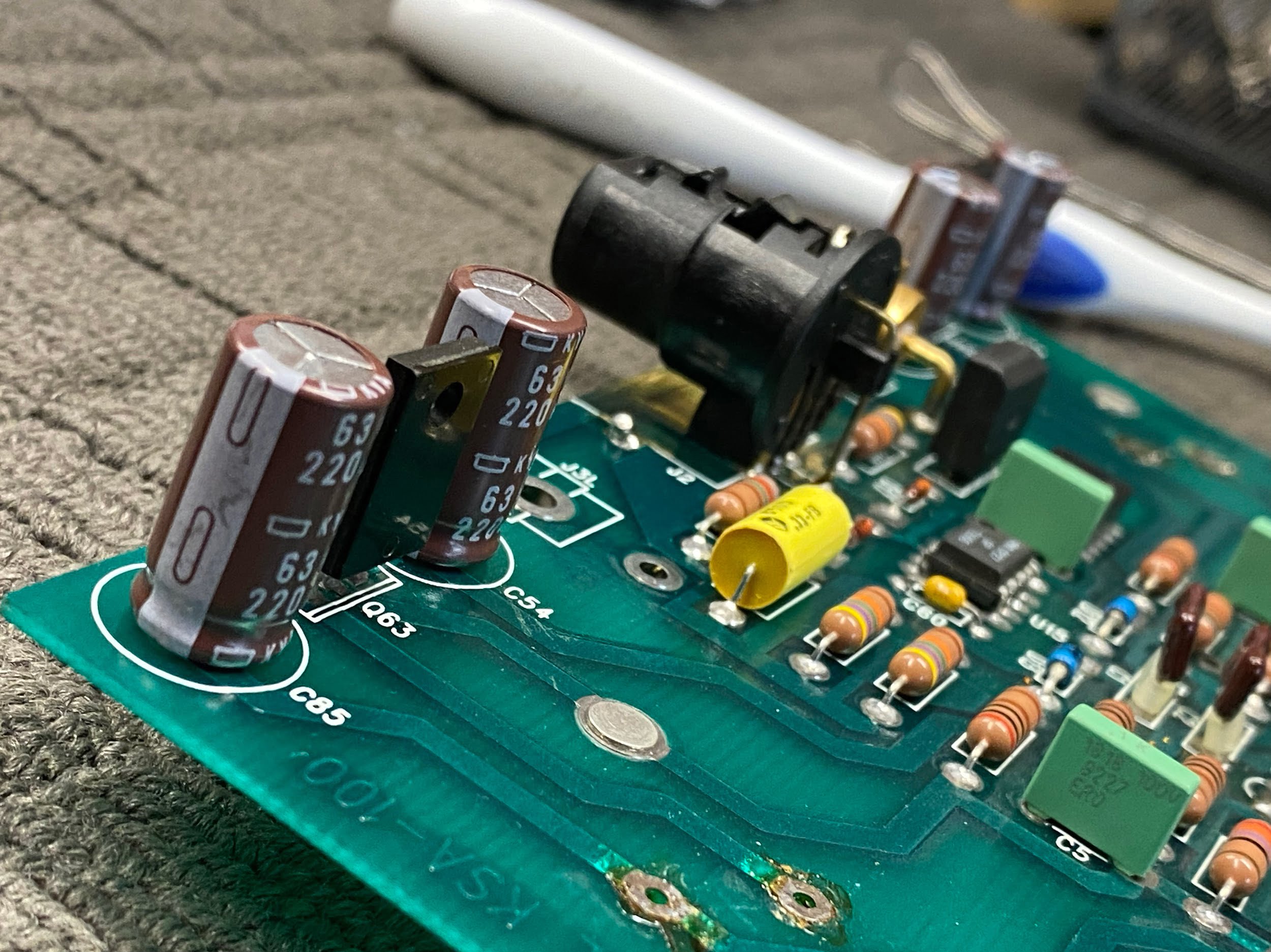
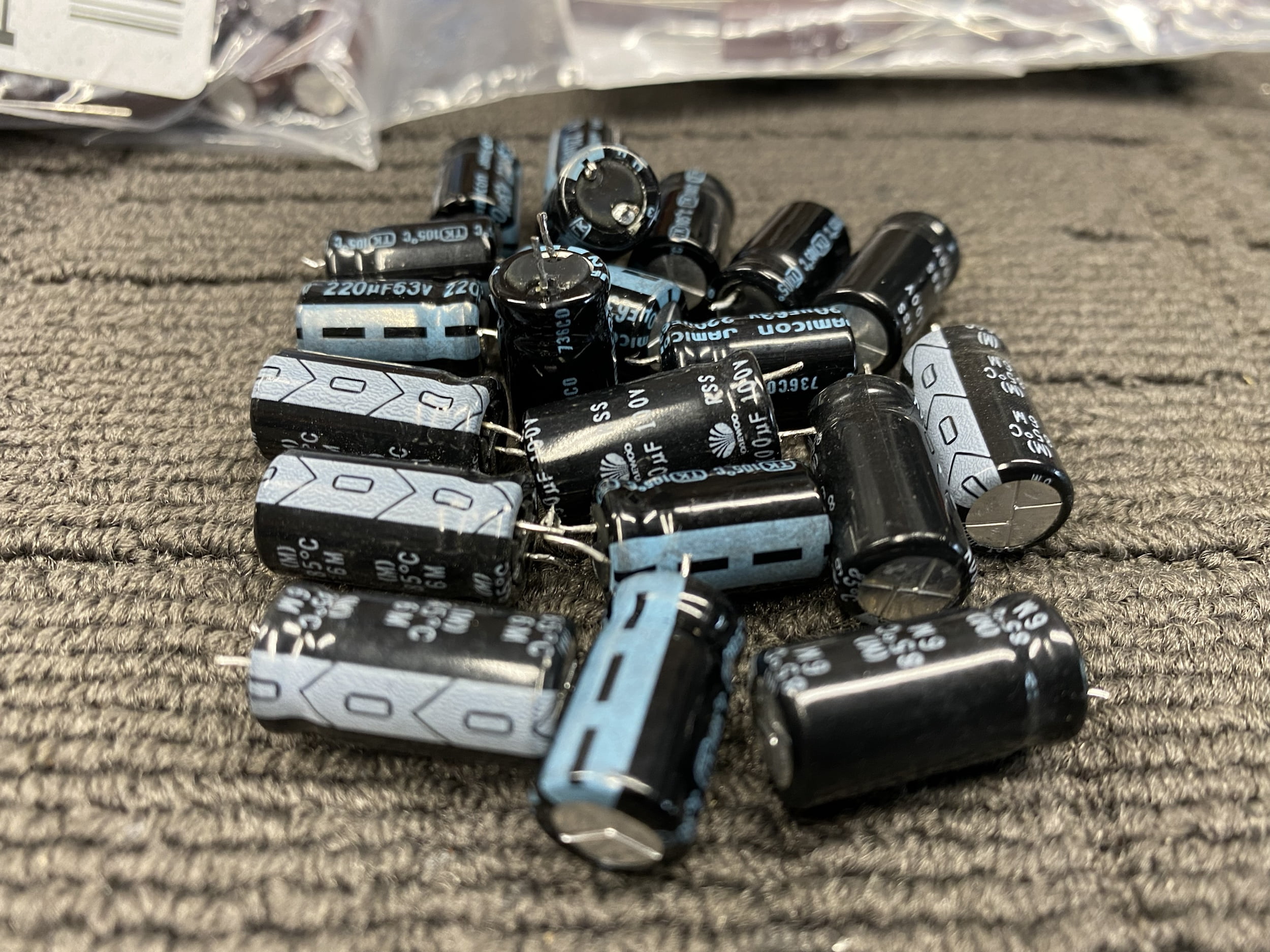
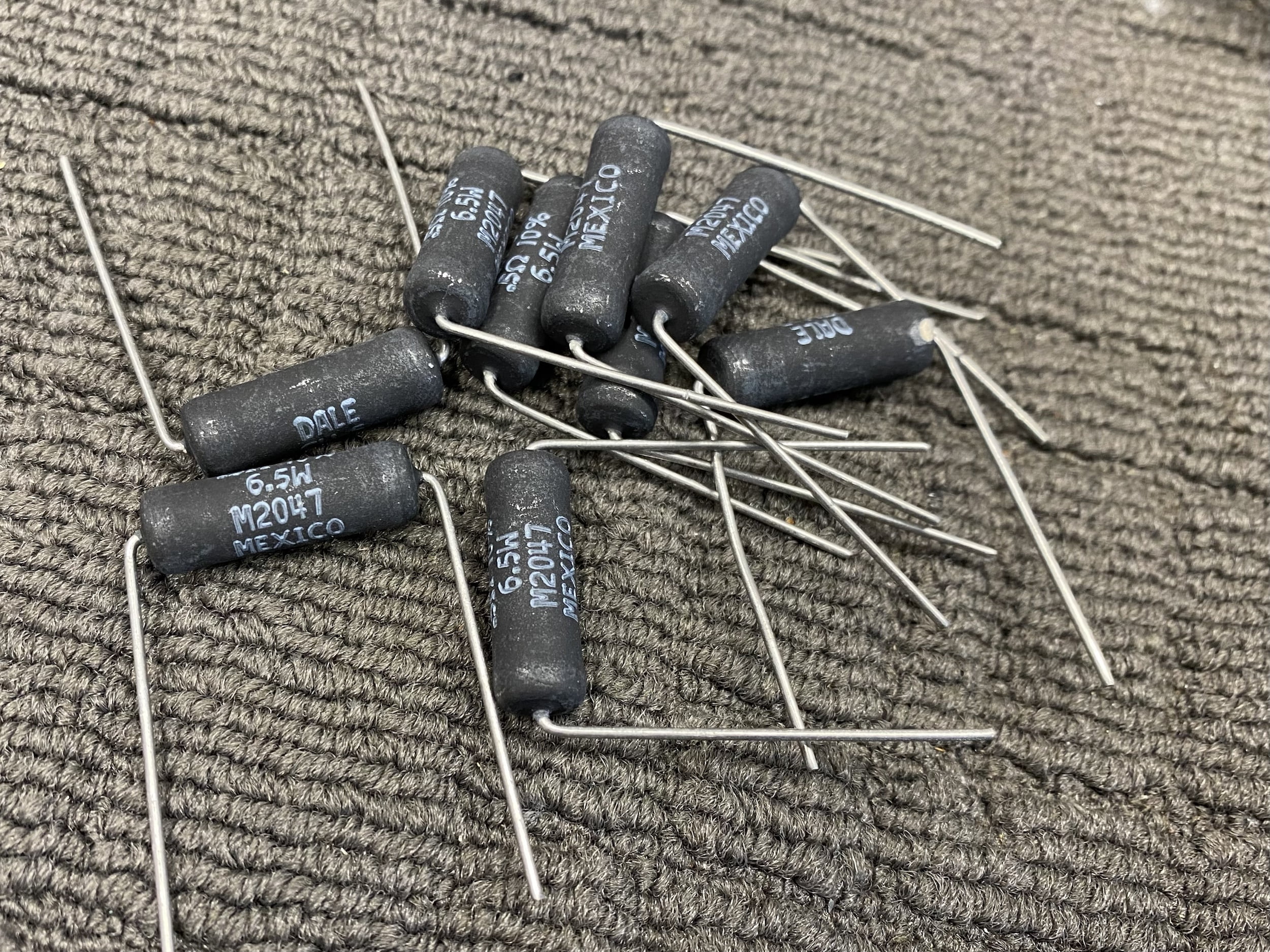
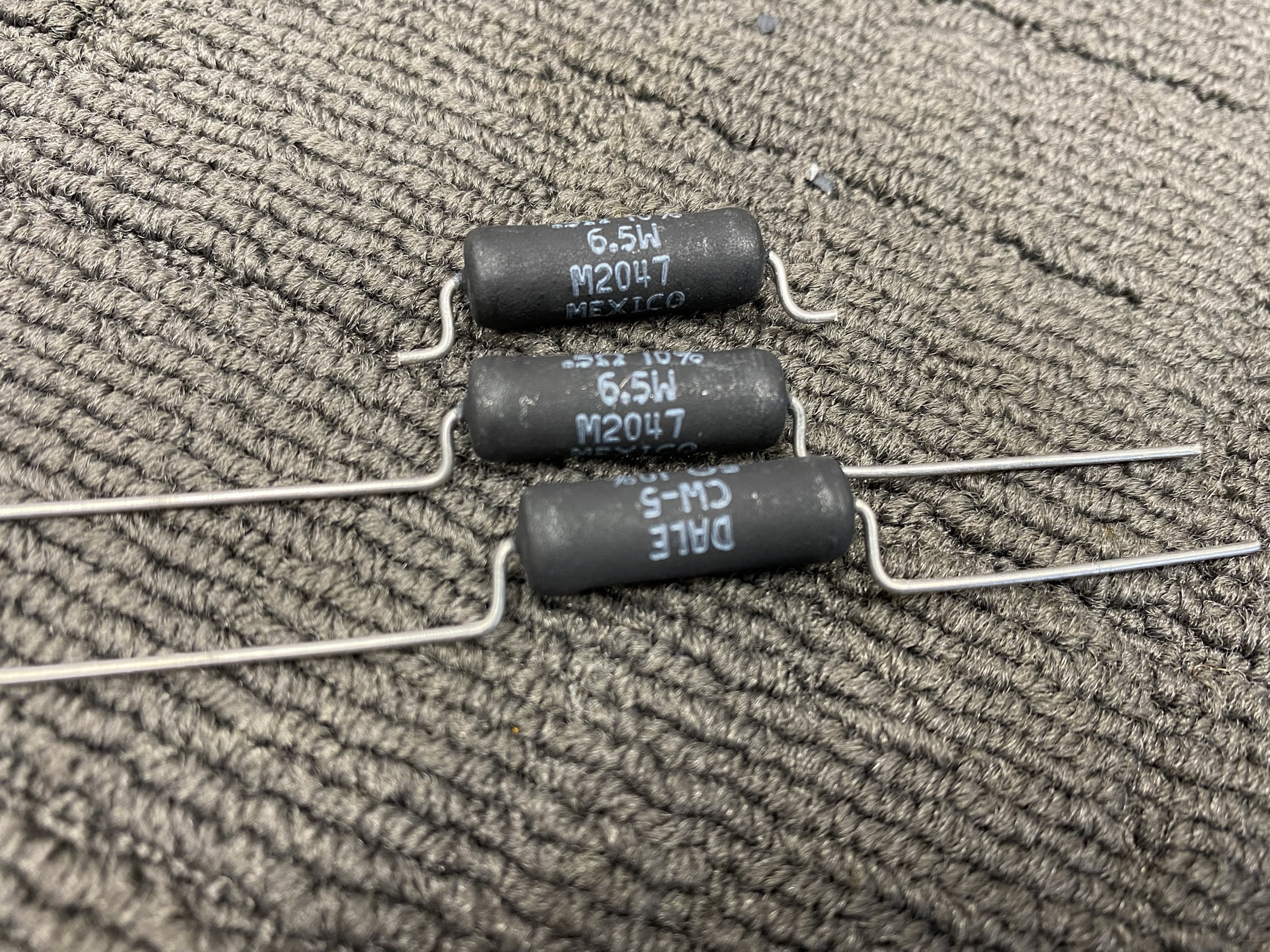
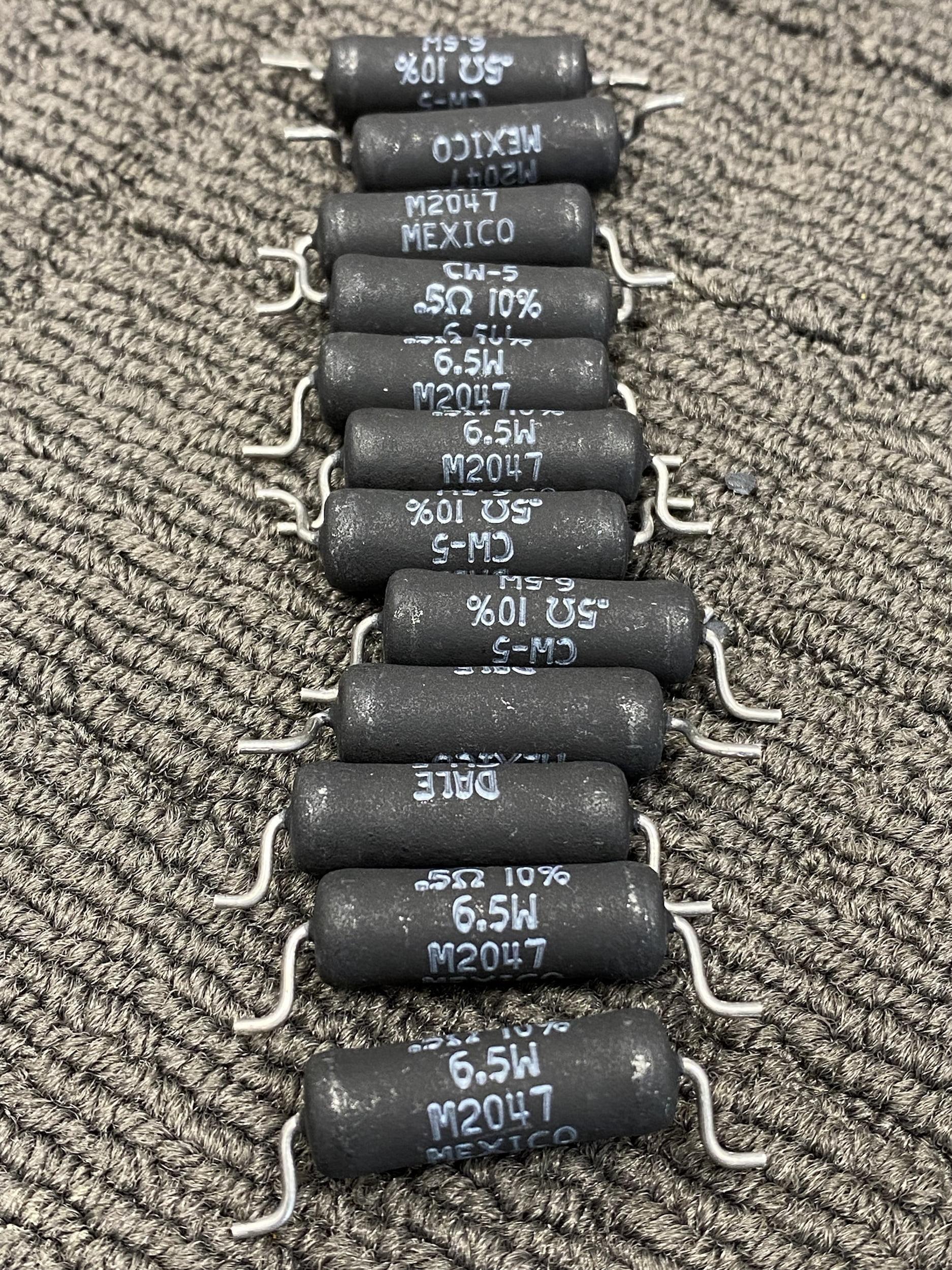
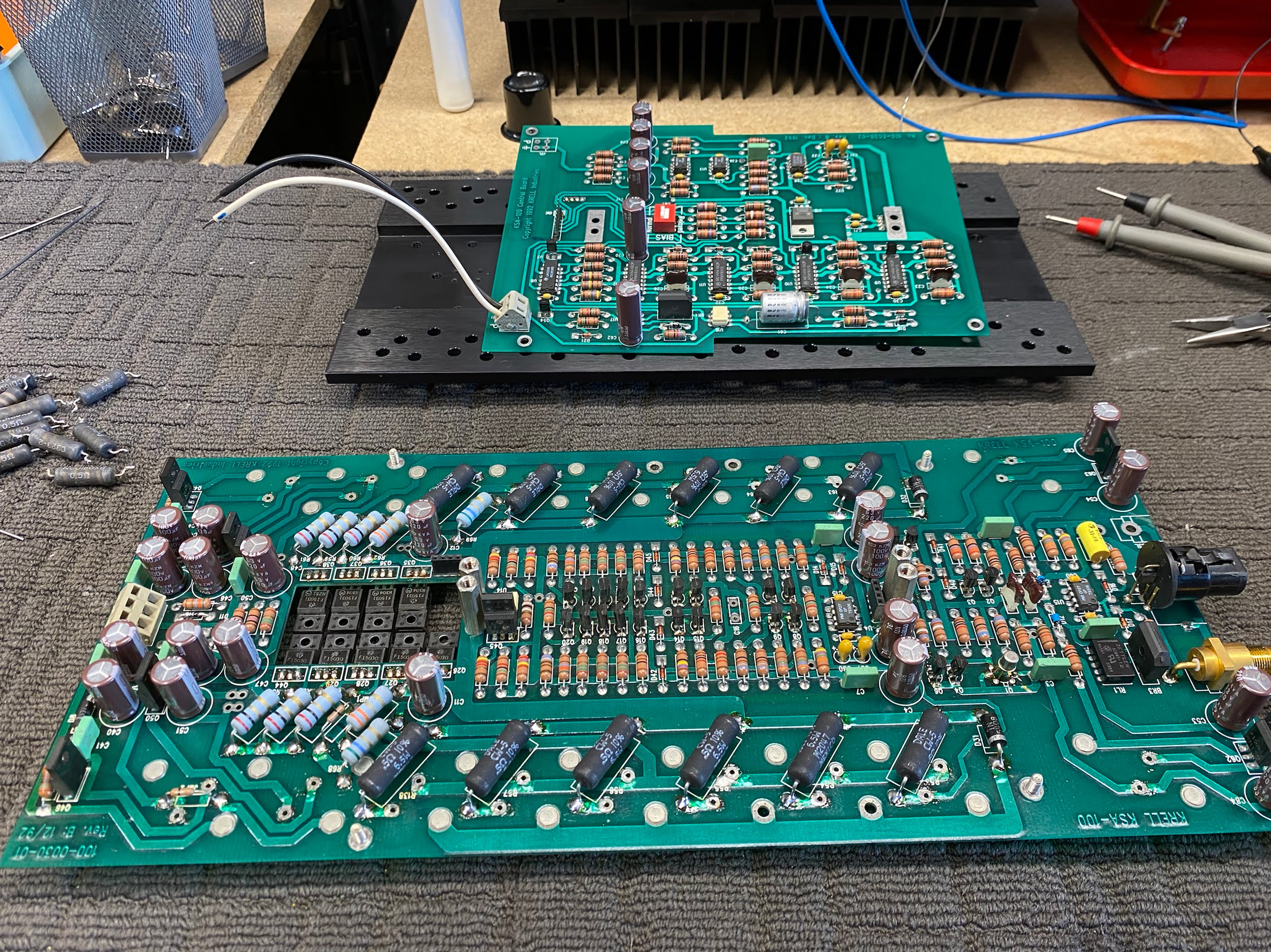
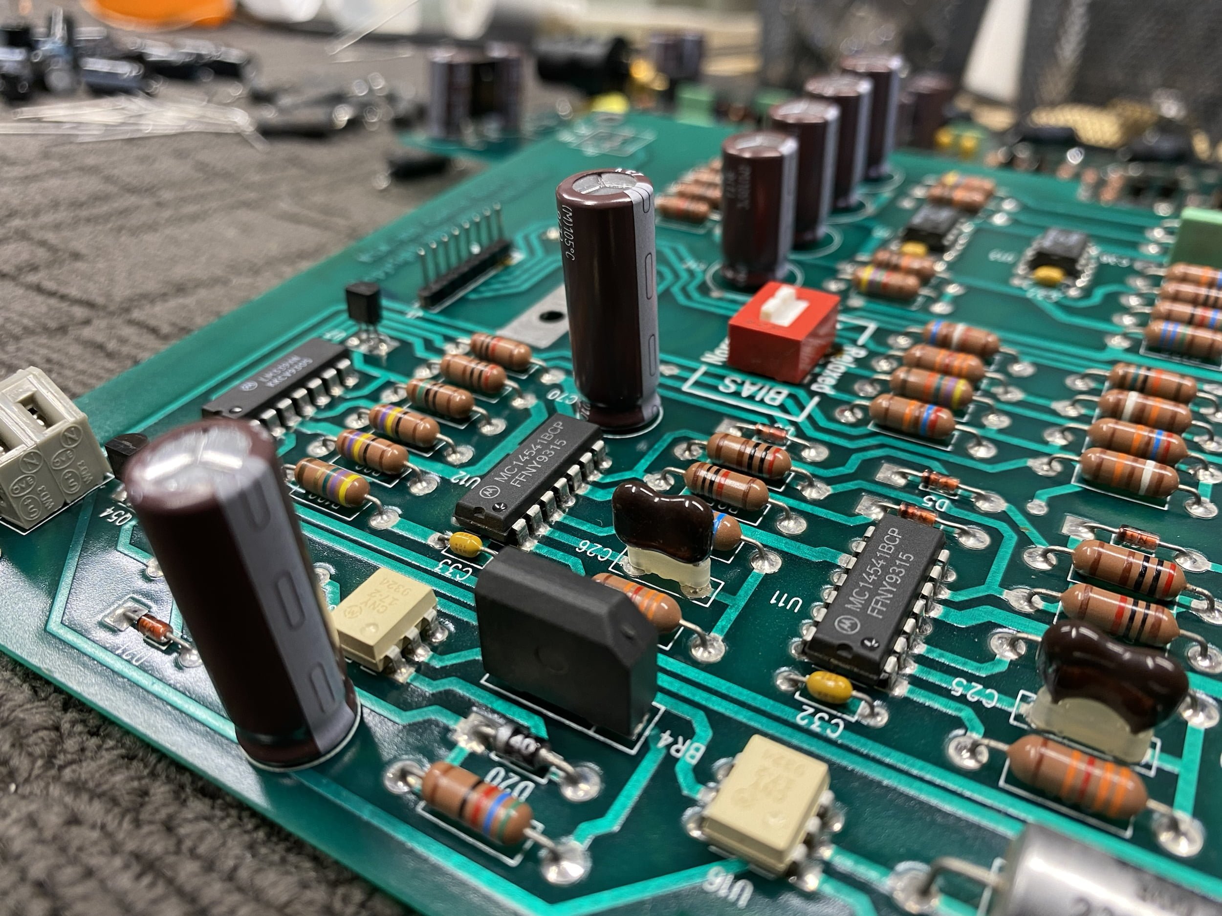
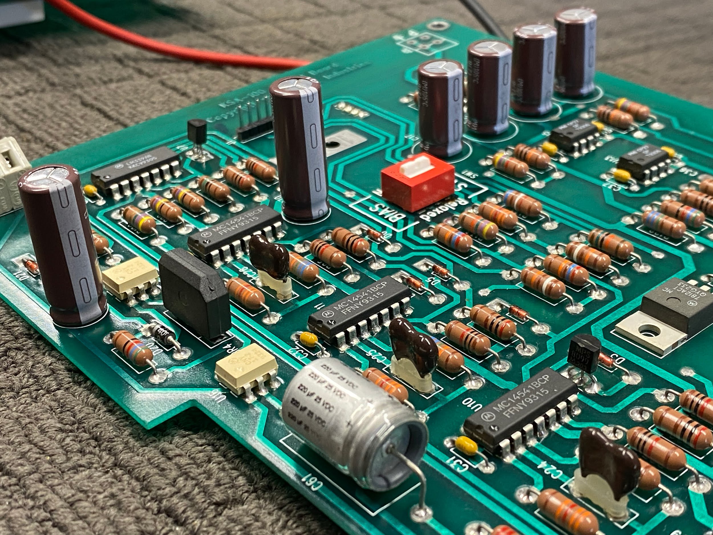
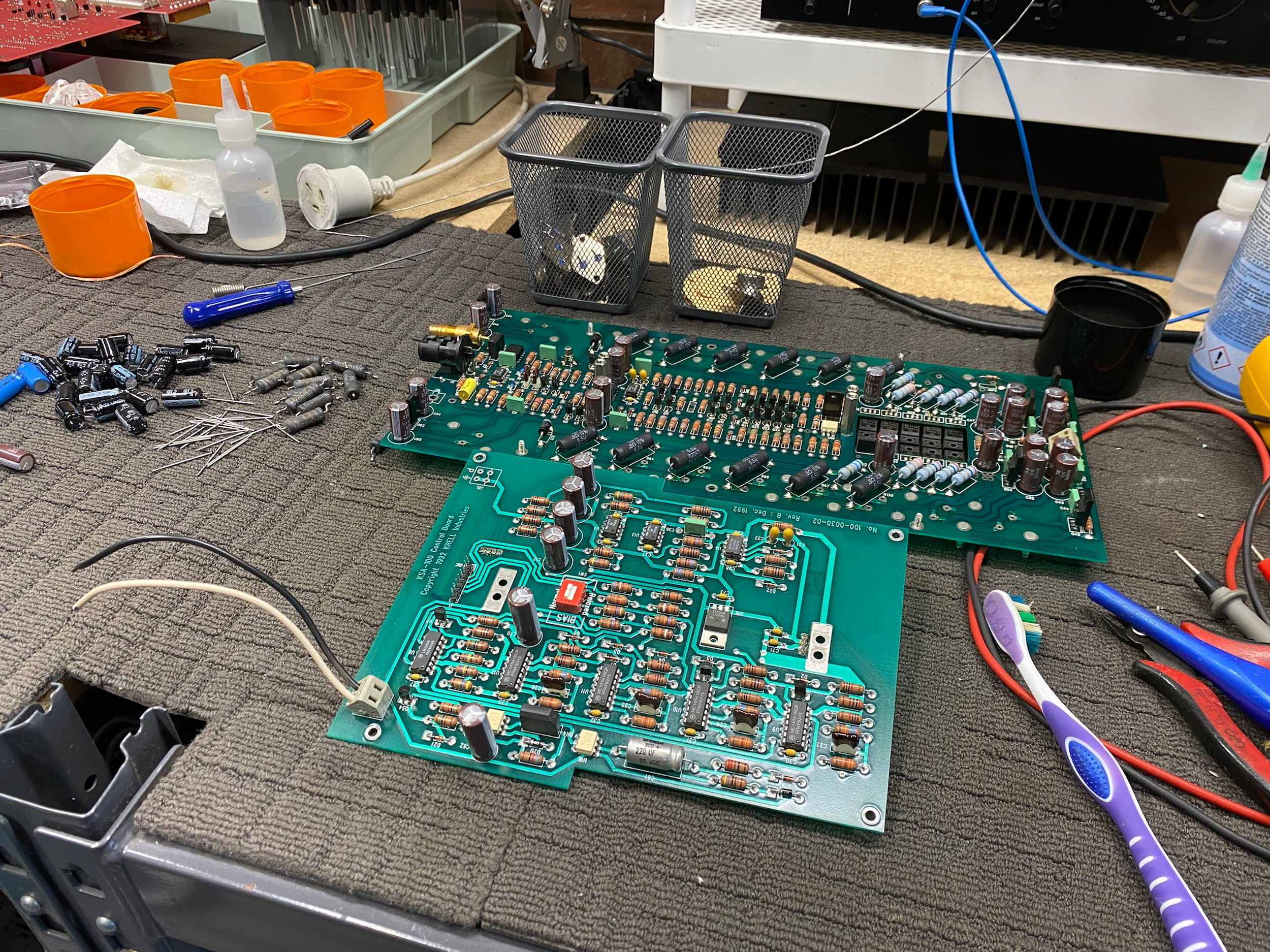
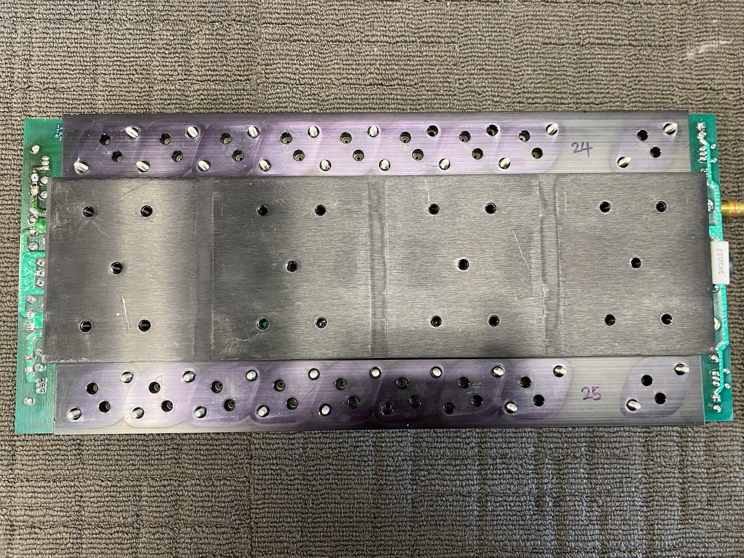
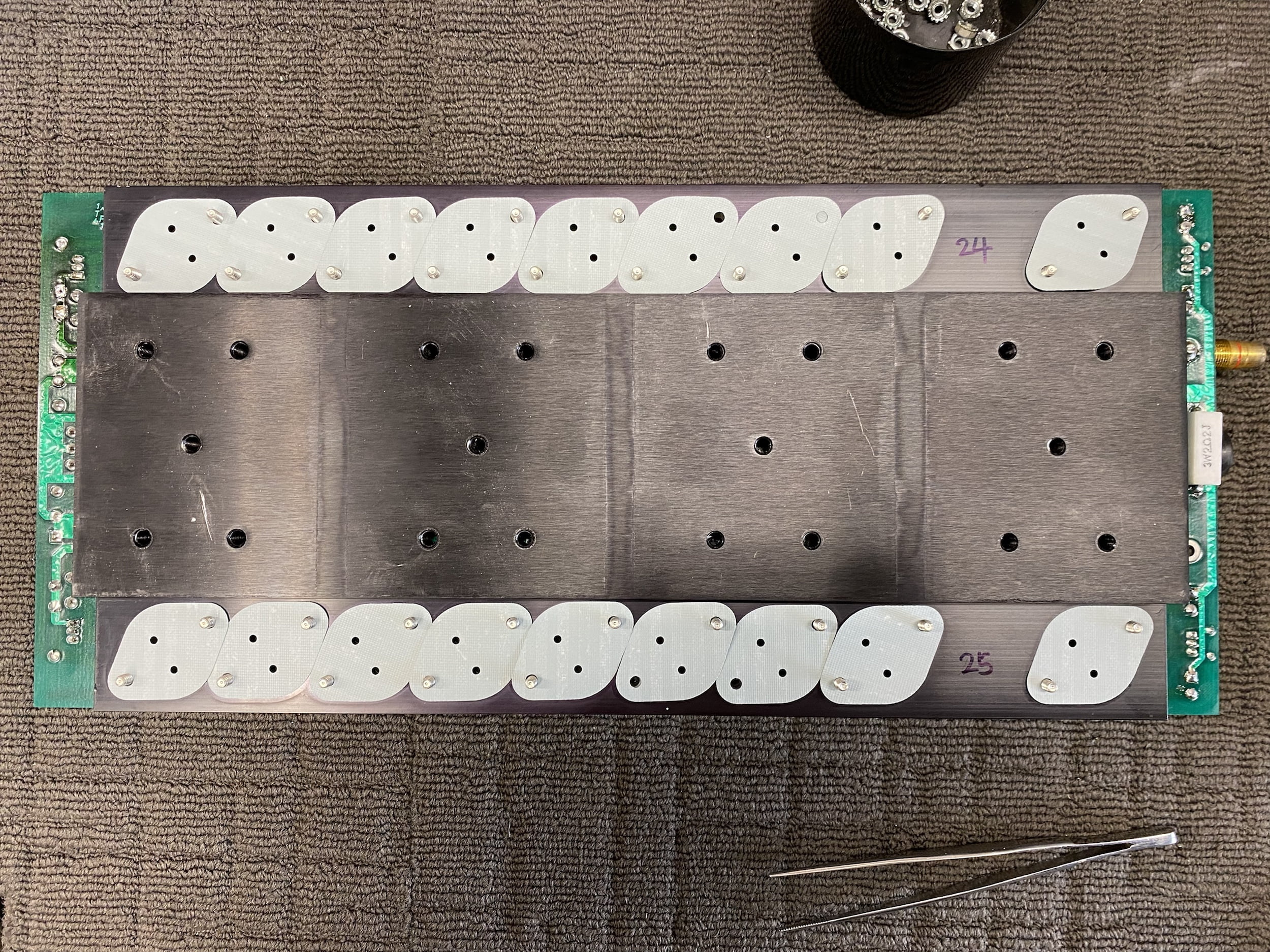
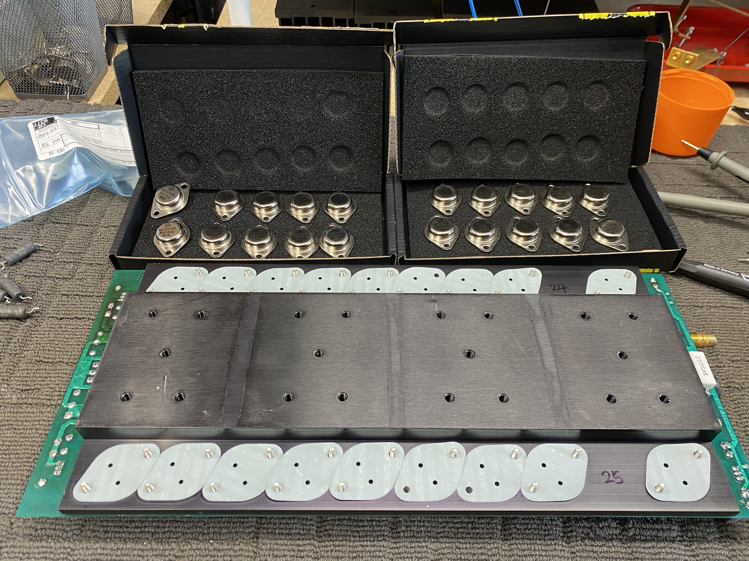
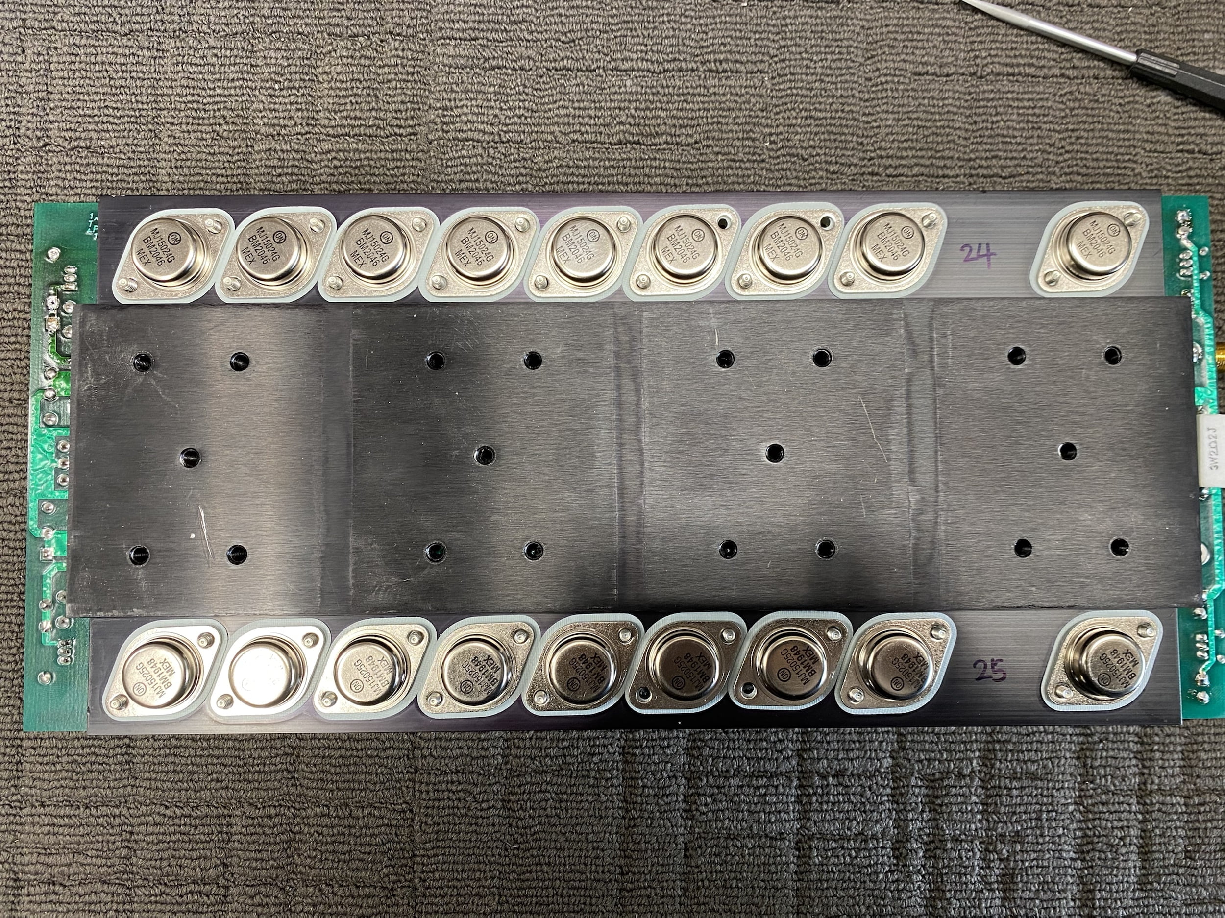
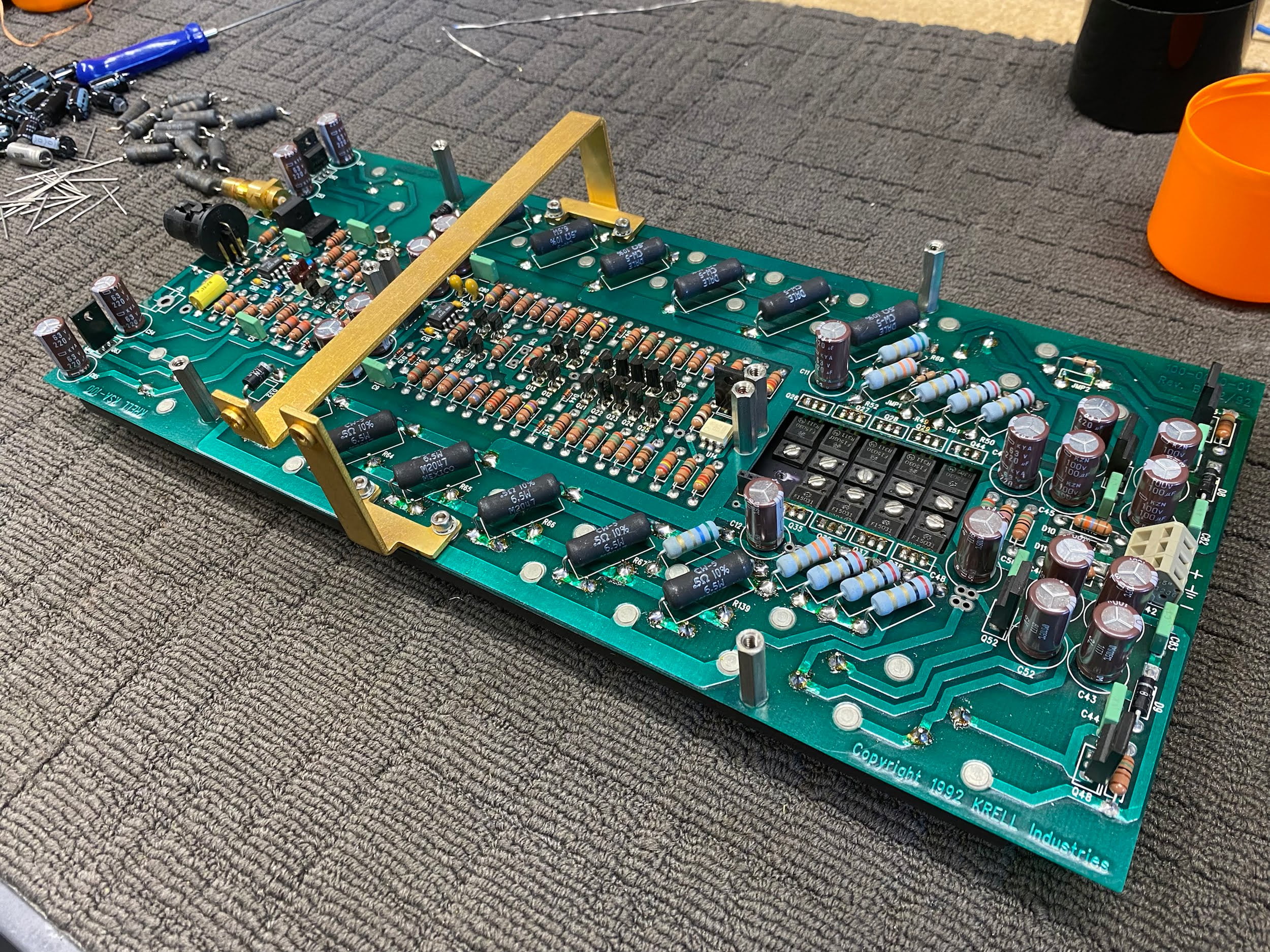
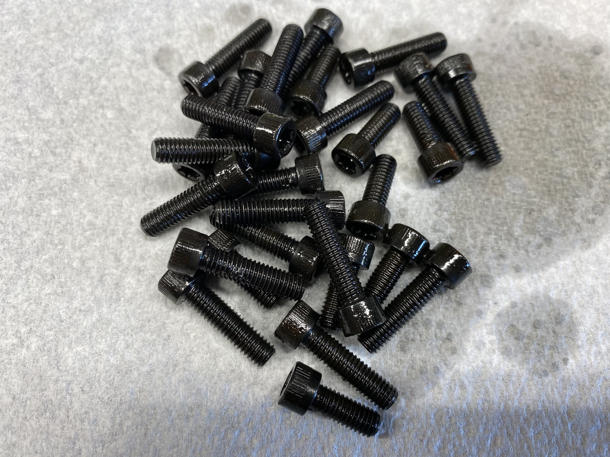
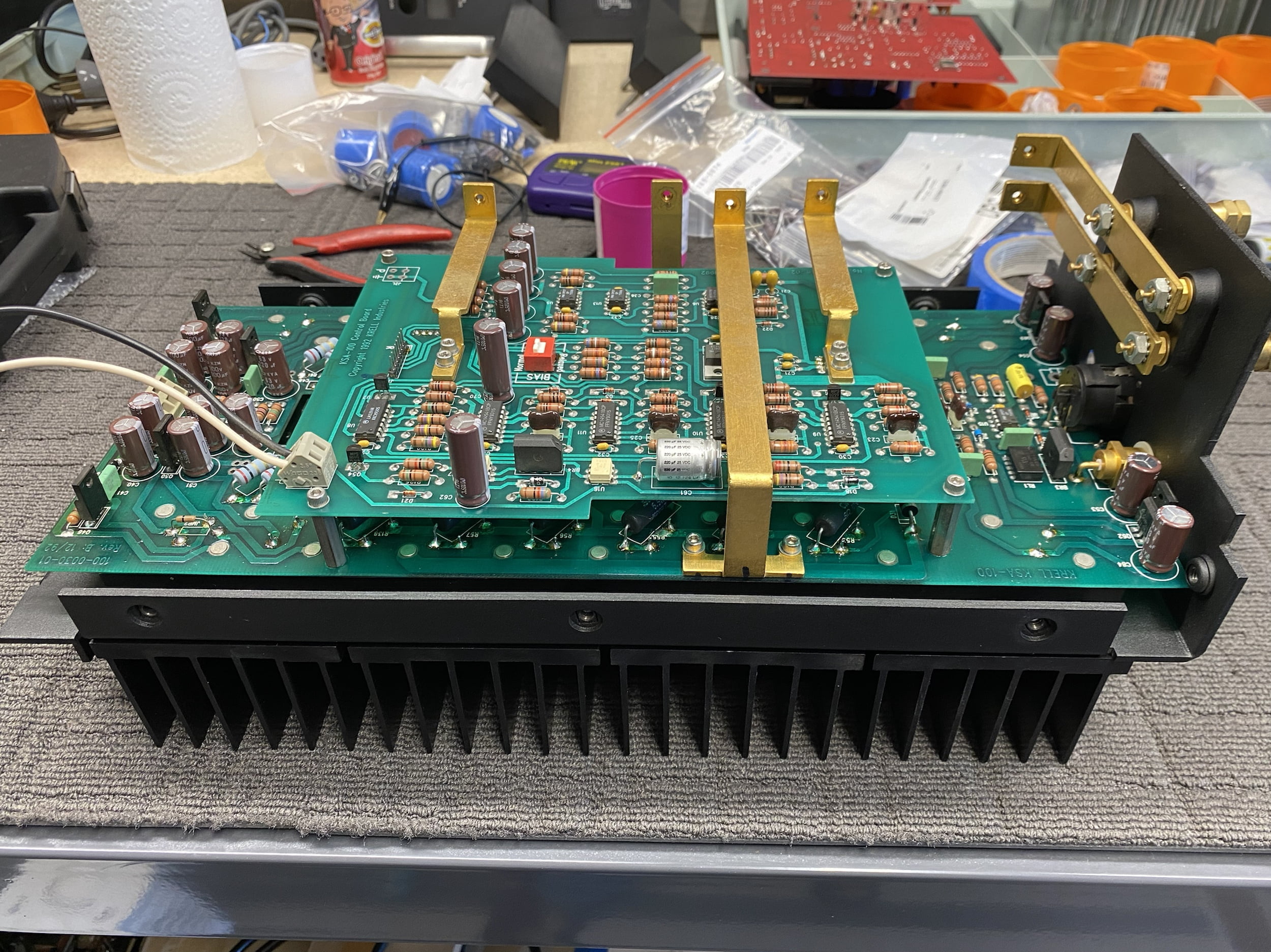
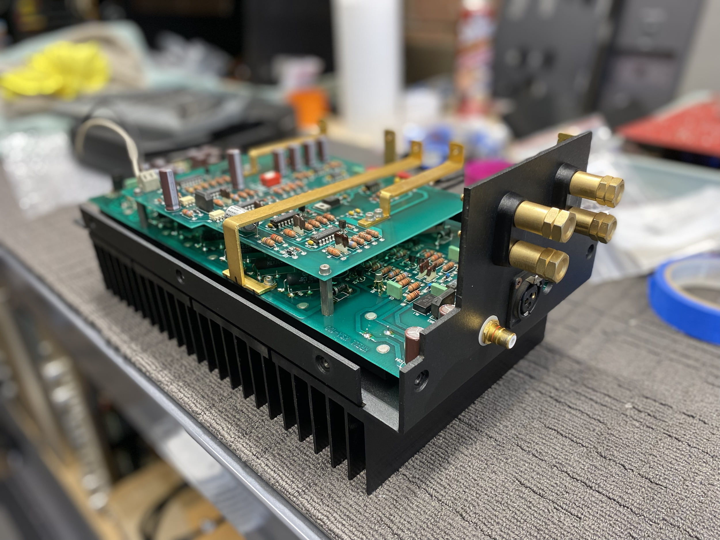
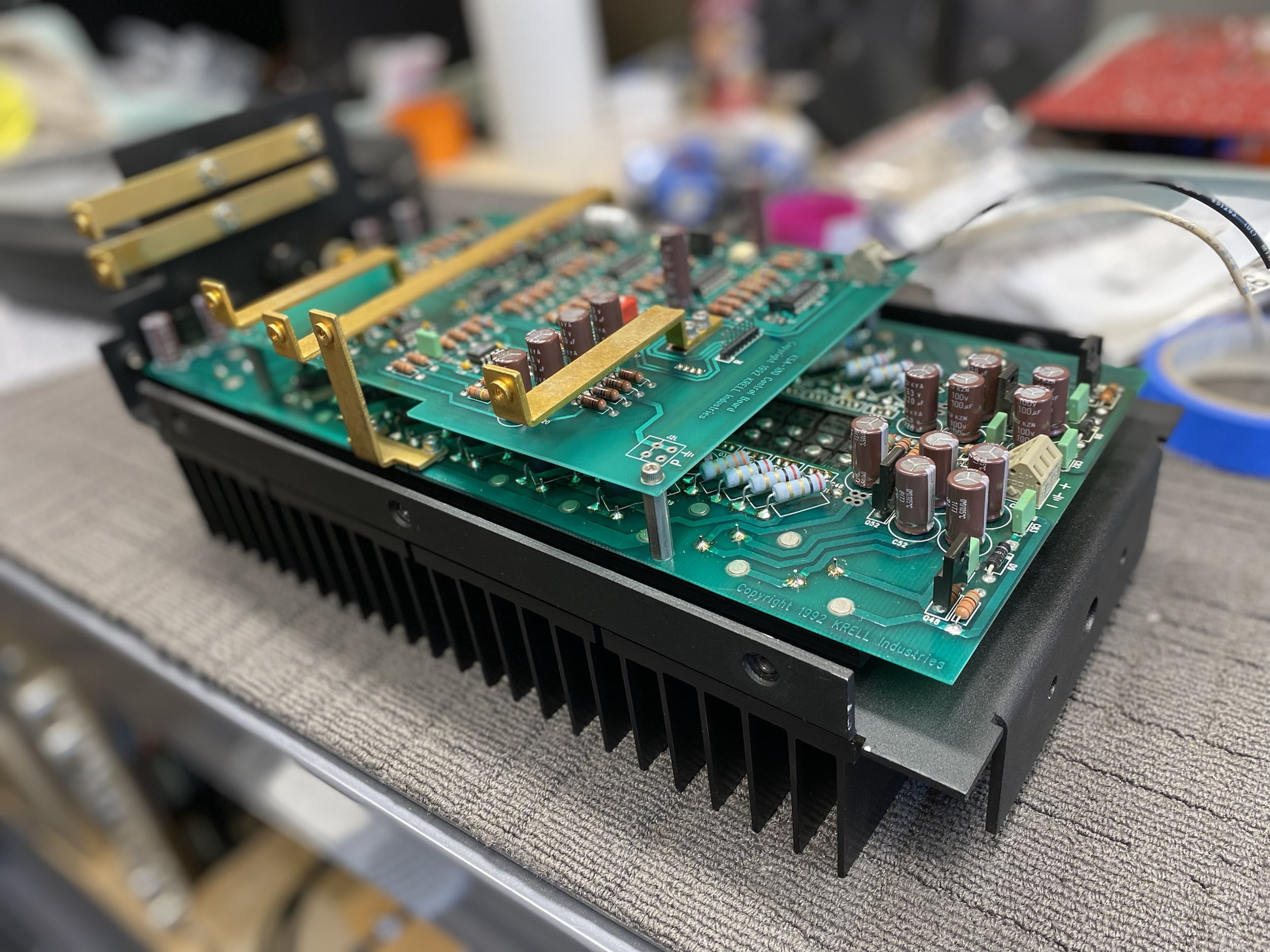
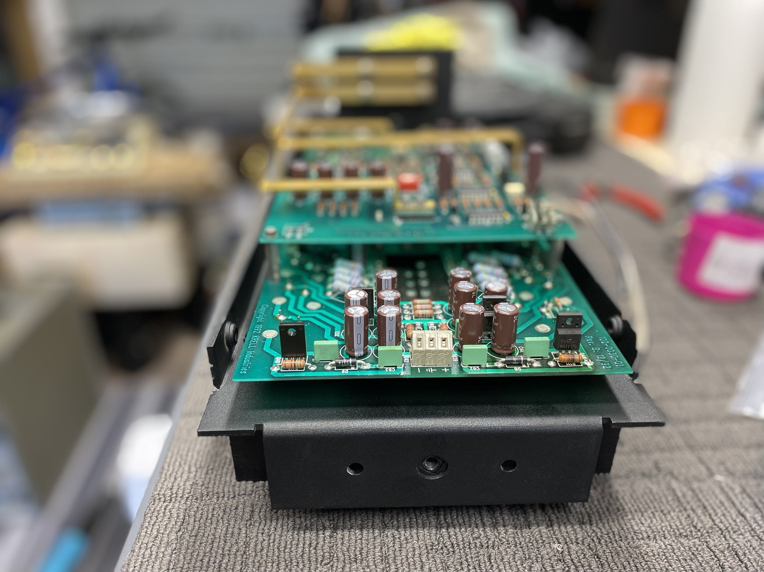
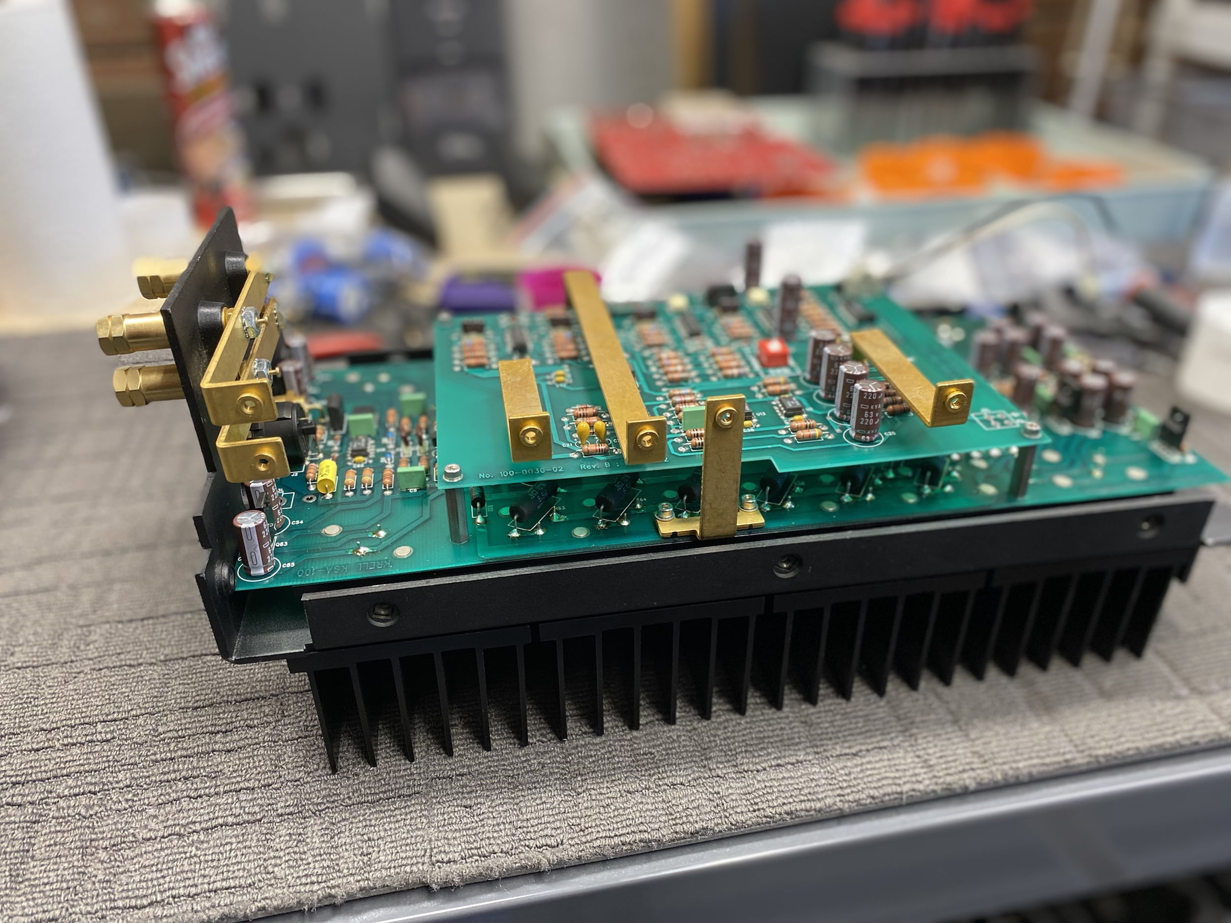
OK, so let’s really quickly run through the left channel.
Before:
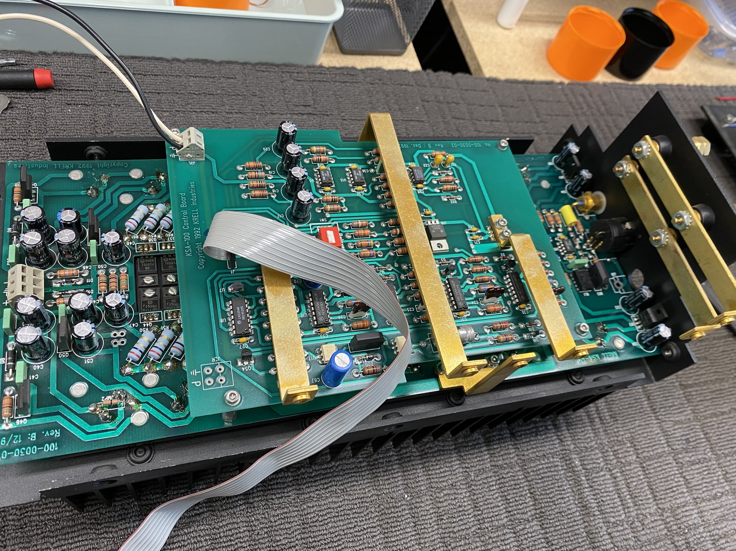
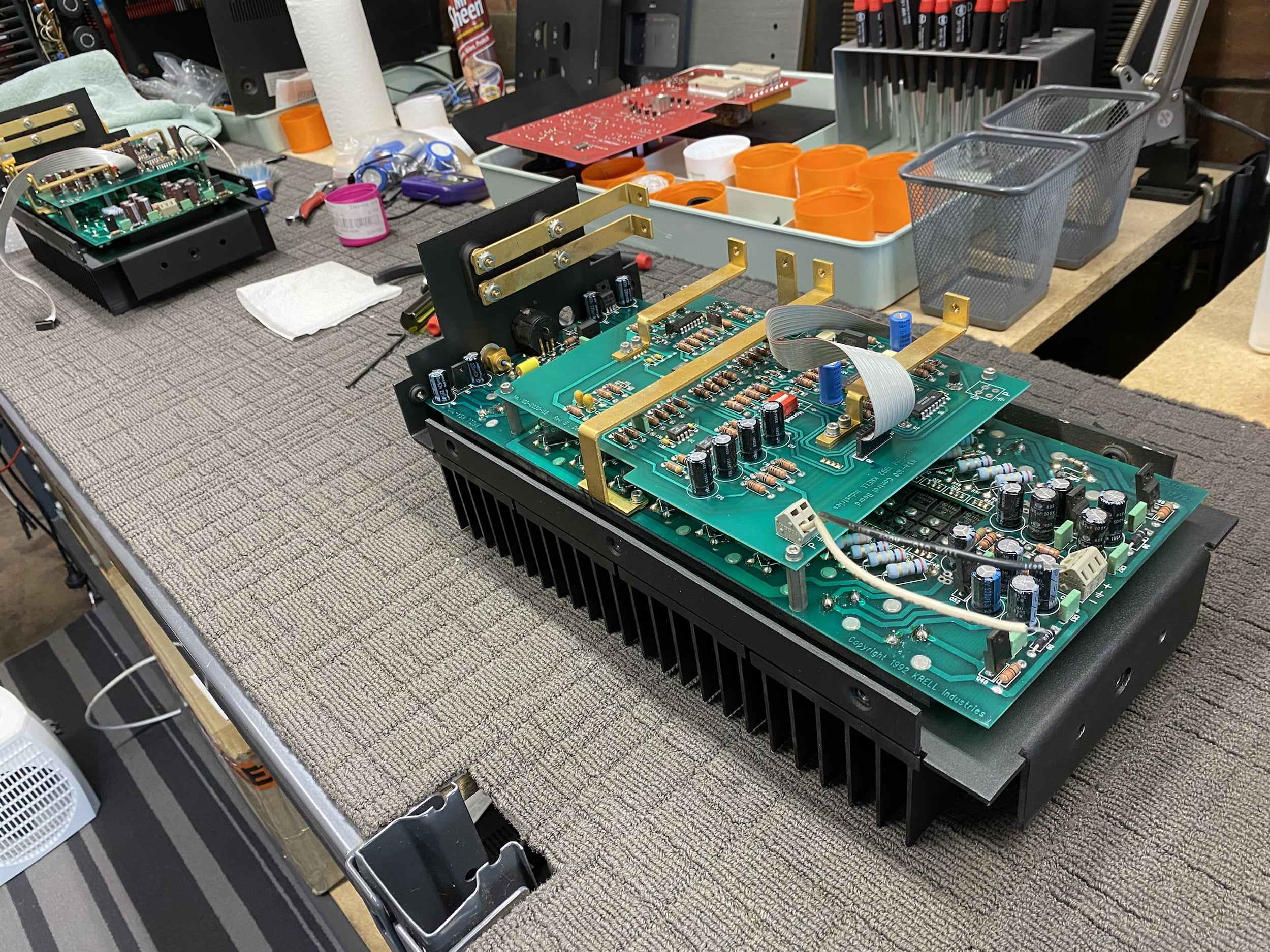
During:
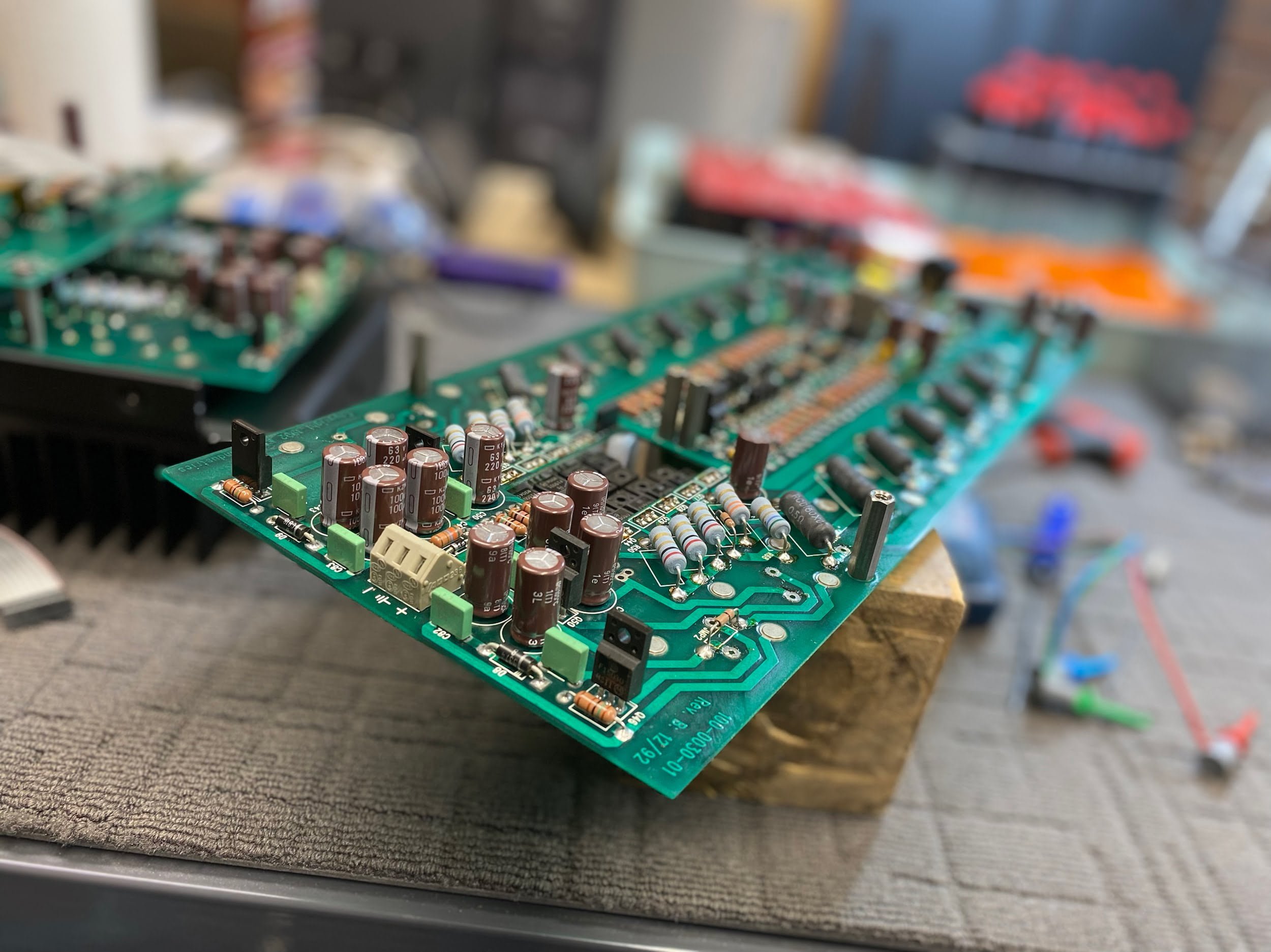
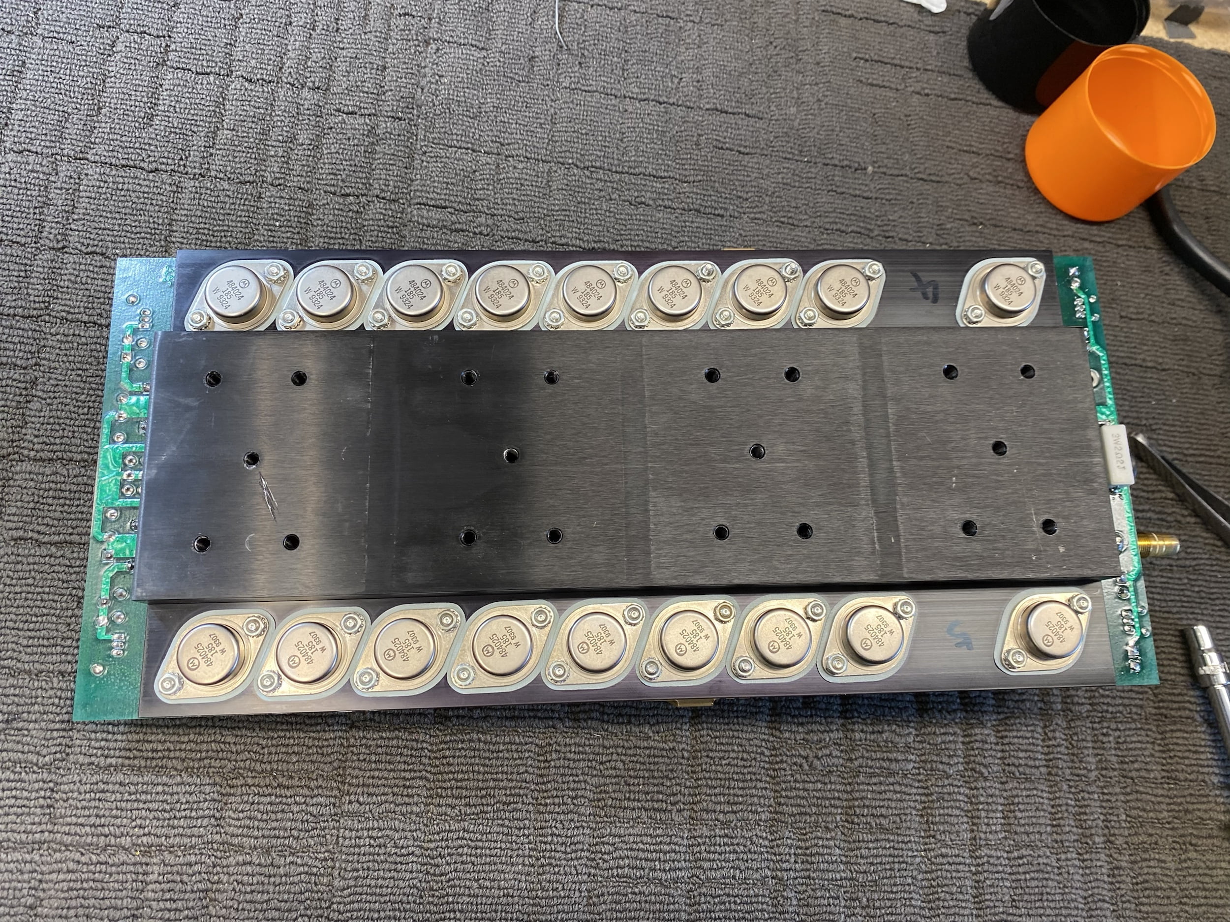
And after:
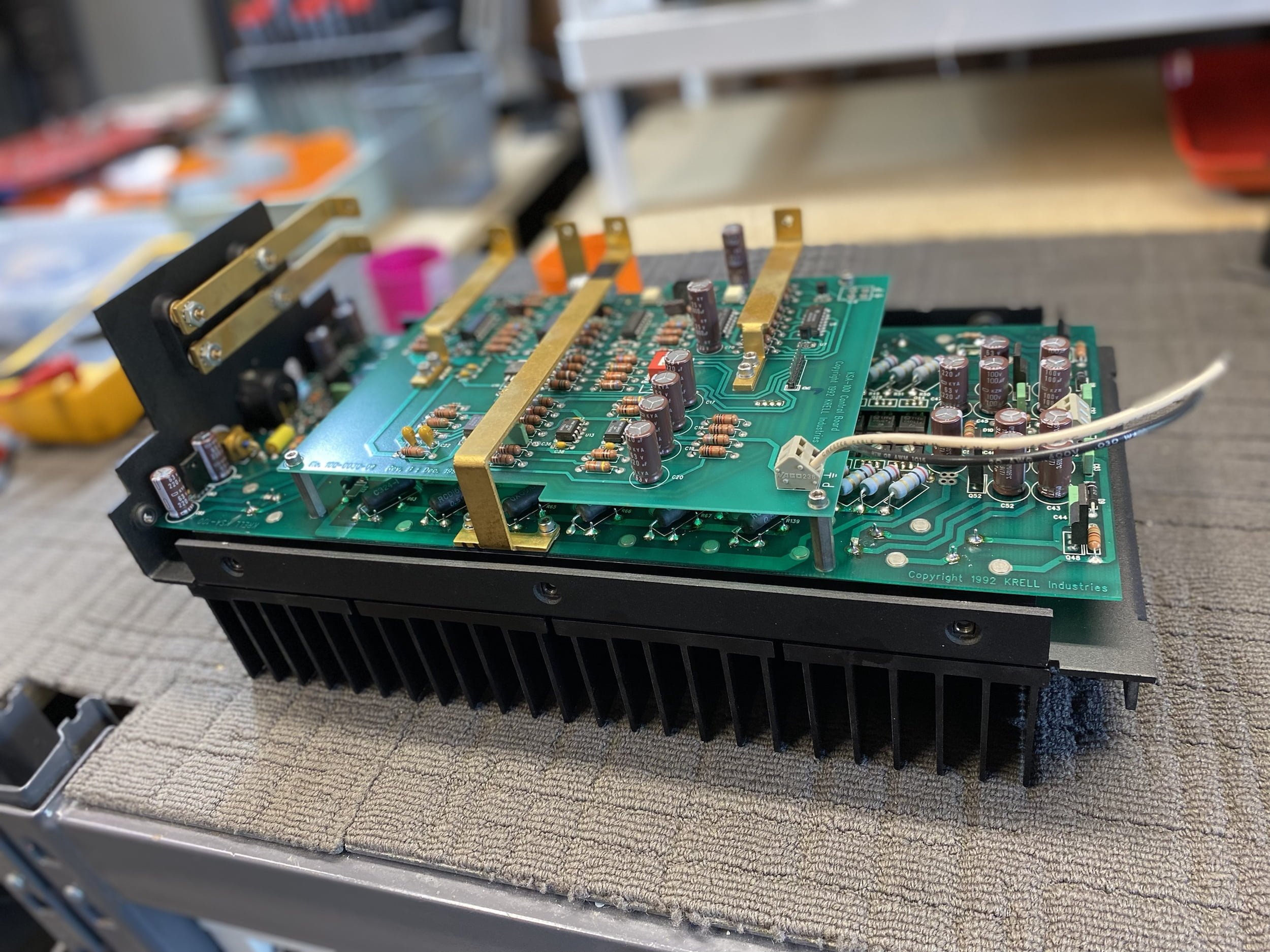
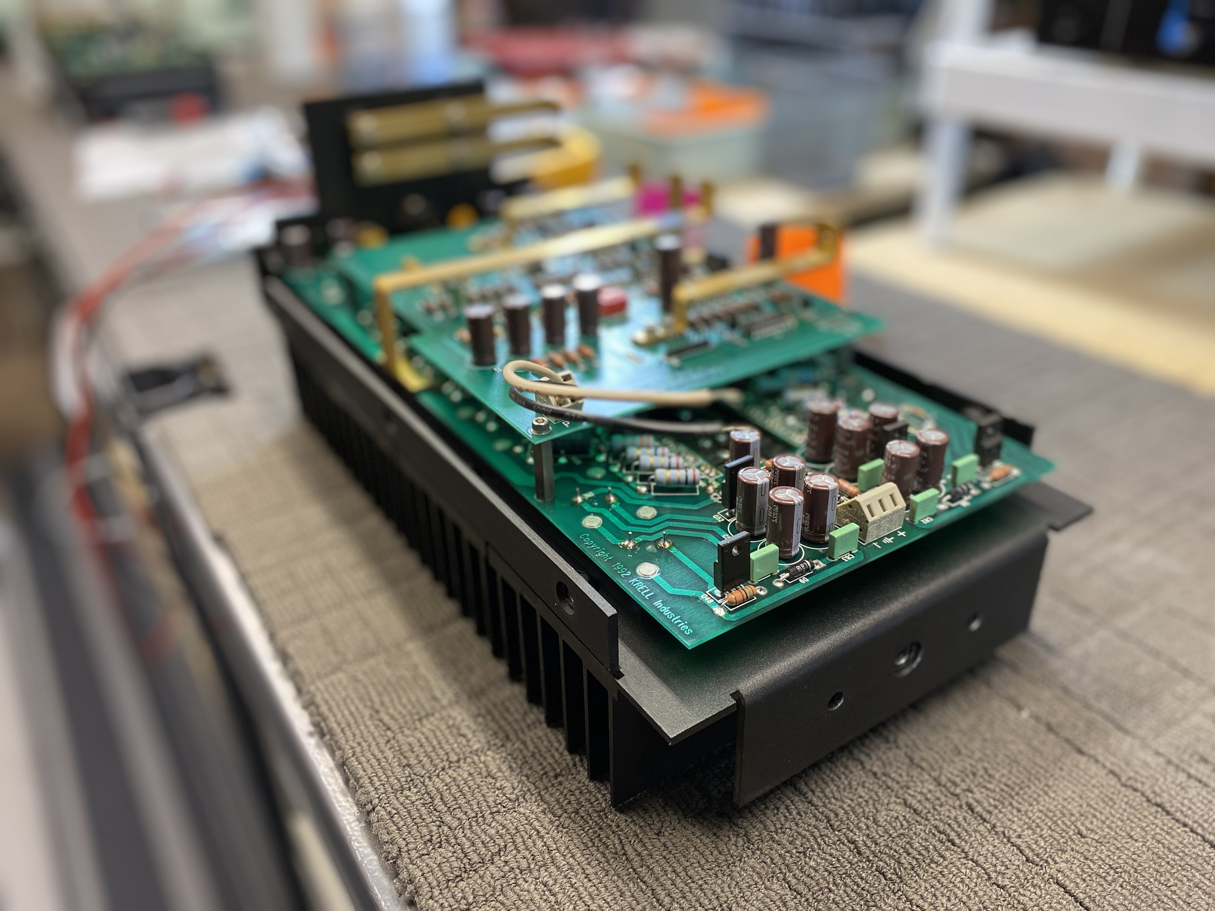
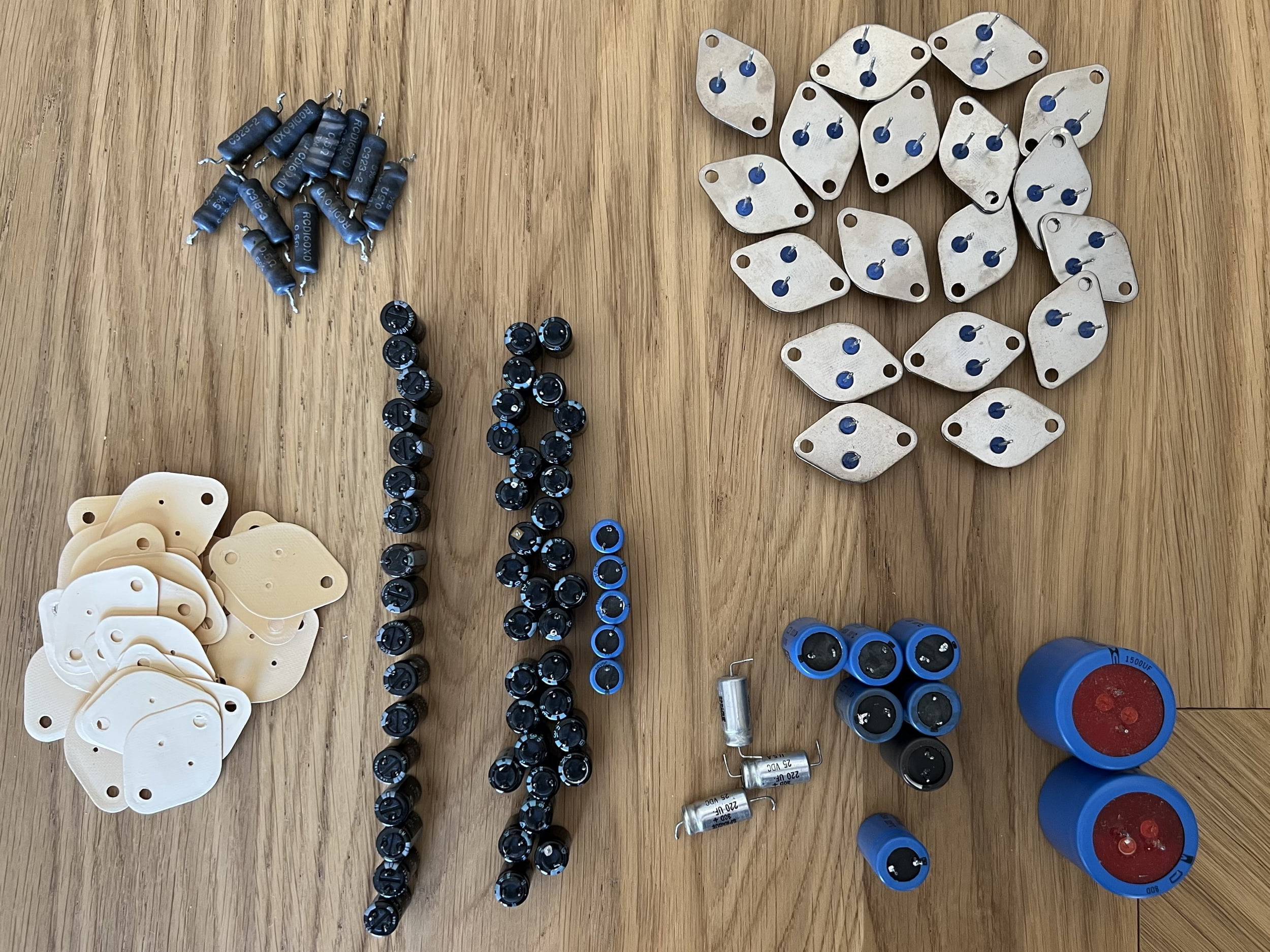
It’s worth mentioning that the left channel had not failed and exhibited no signs of over-current or thermal stress. I retained and re-used the original output devices and emitter resistors as these tested and measured perfectly and this saved considerably on the total bill, with no performance or reliability penalty. Naturally, new thermal pads were installed and all the same restorative work was done on the channel.
Control Module
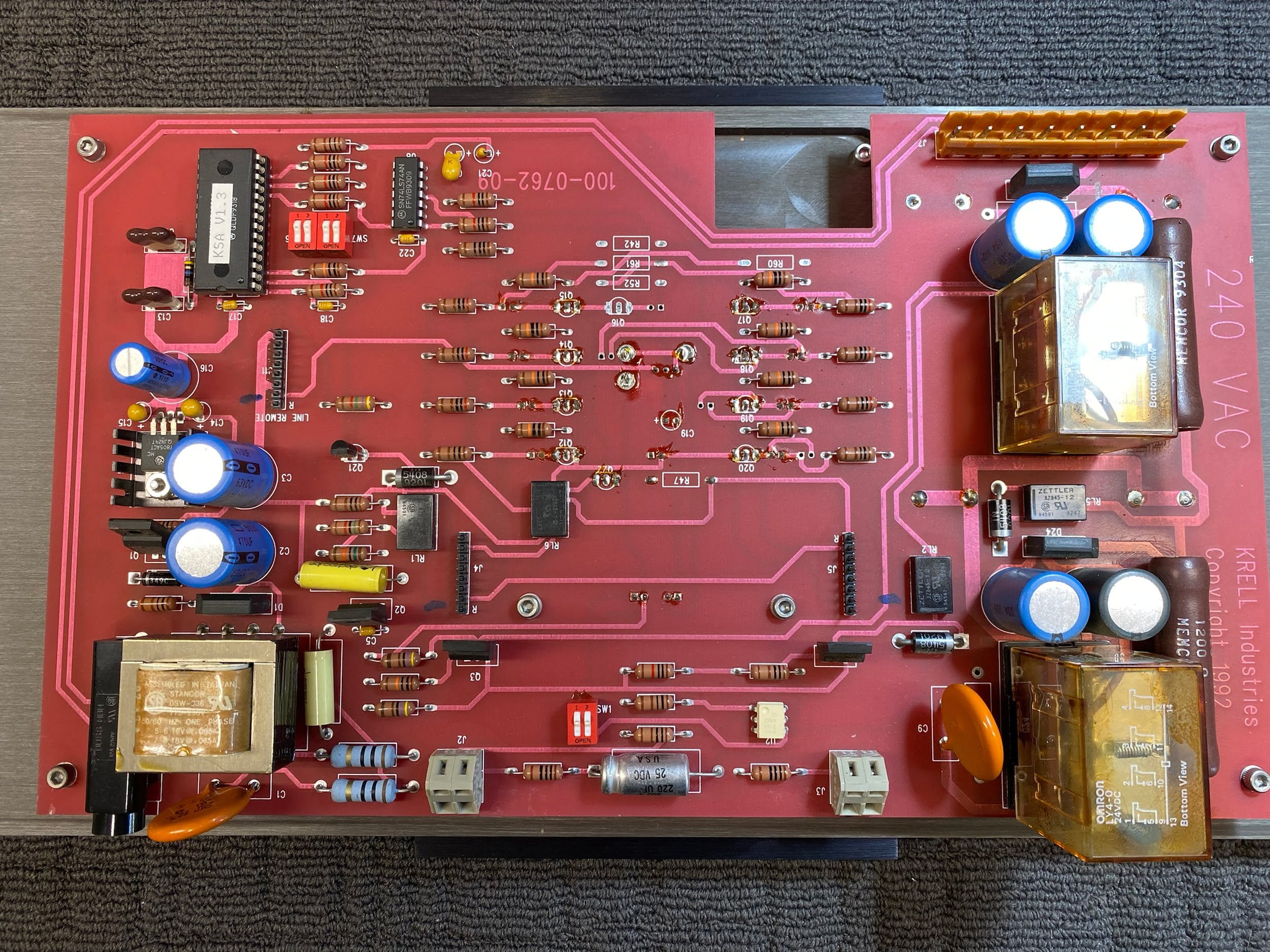
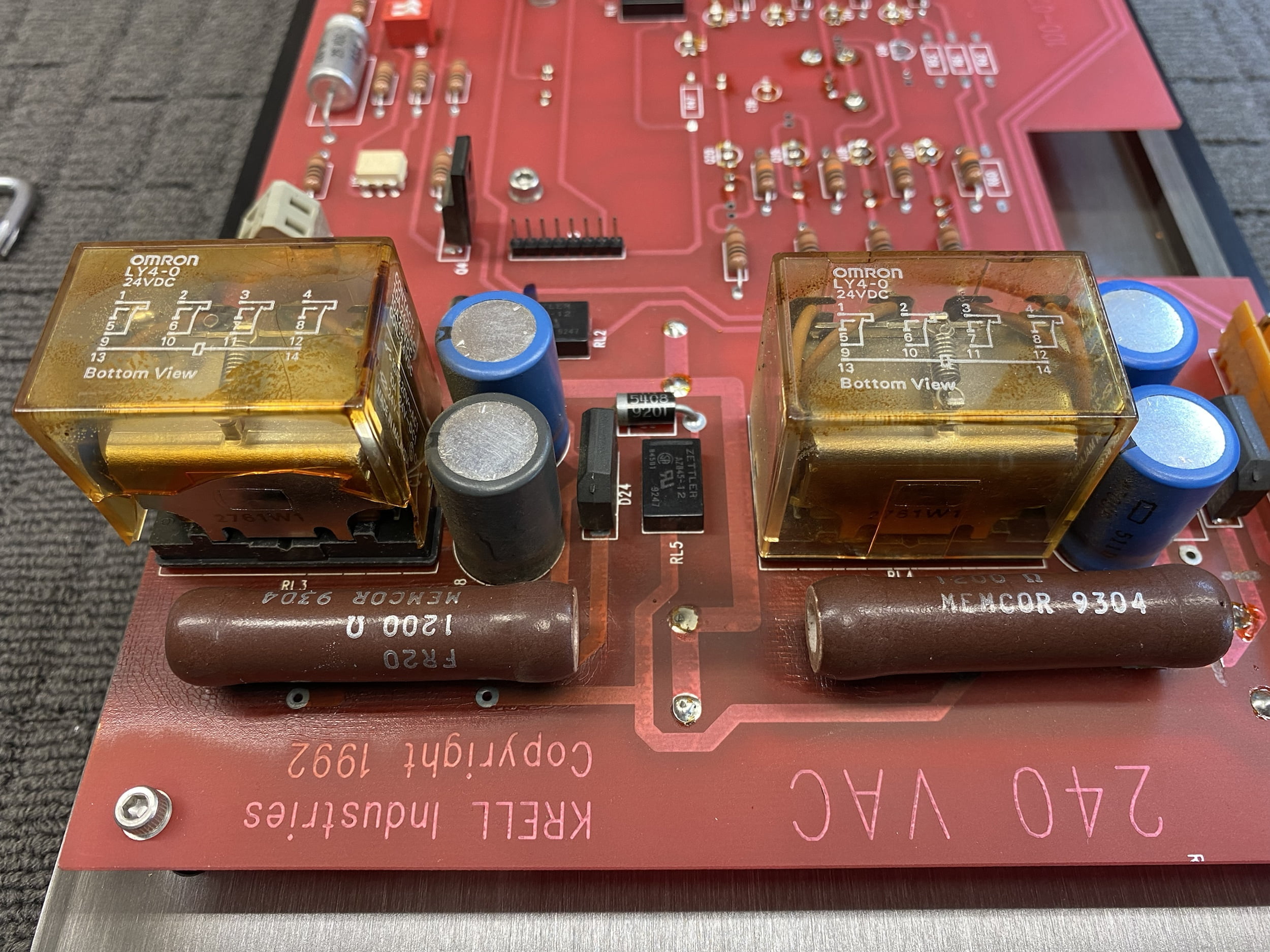
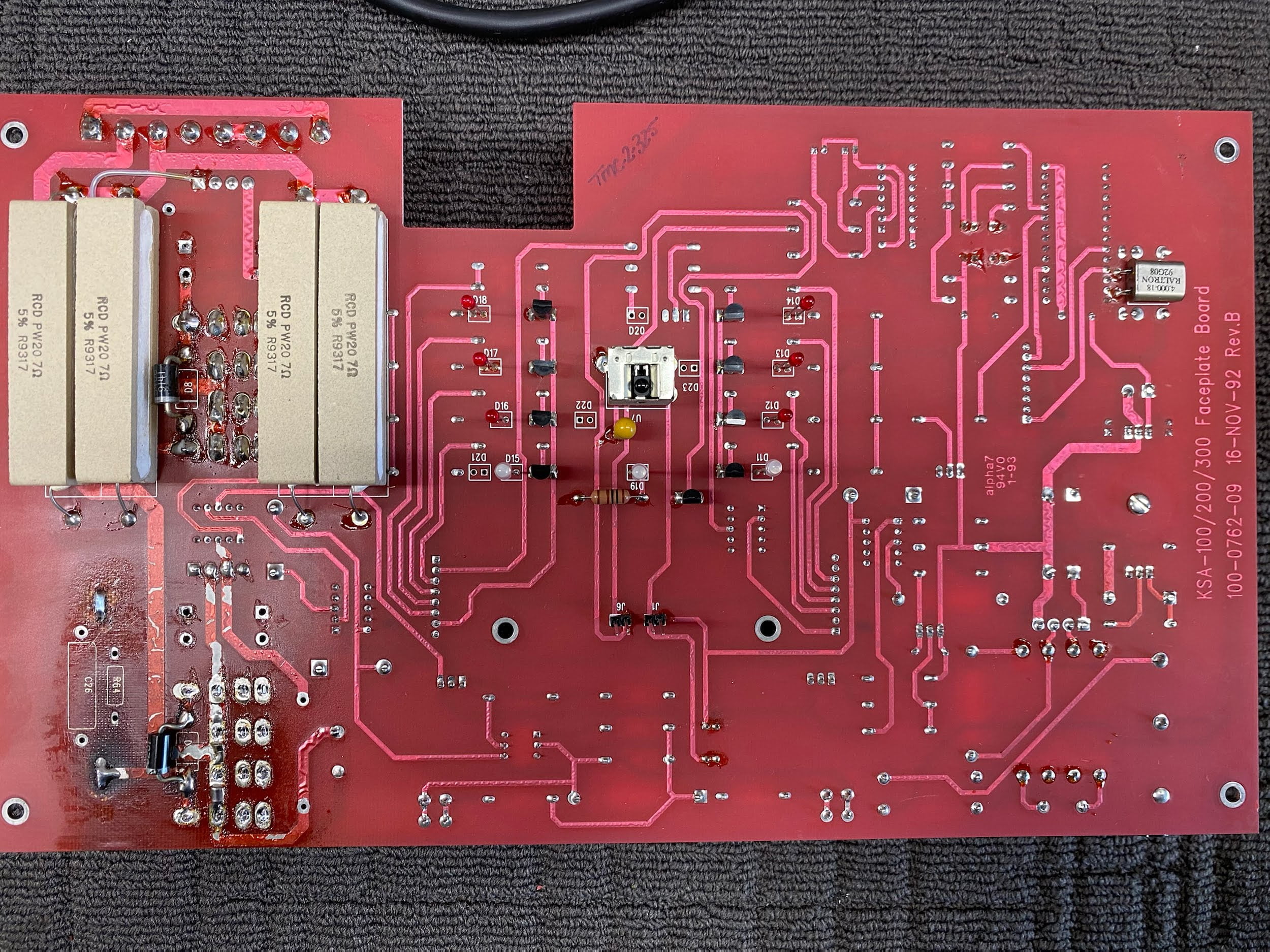
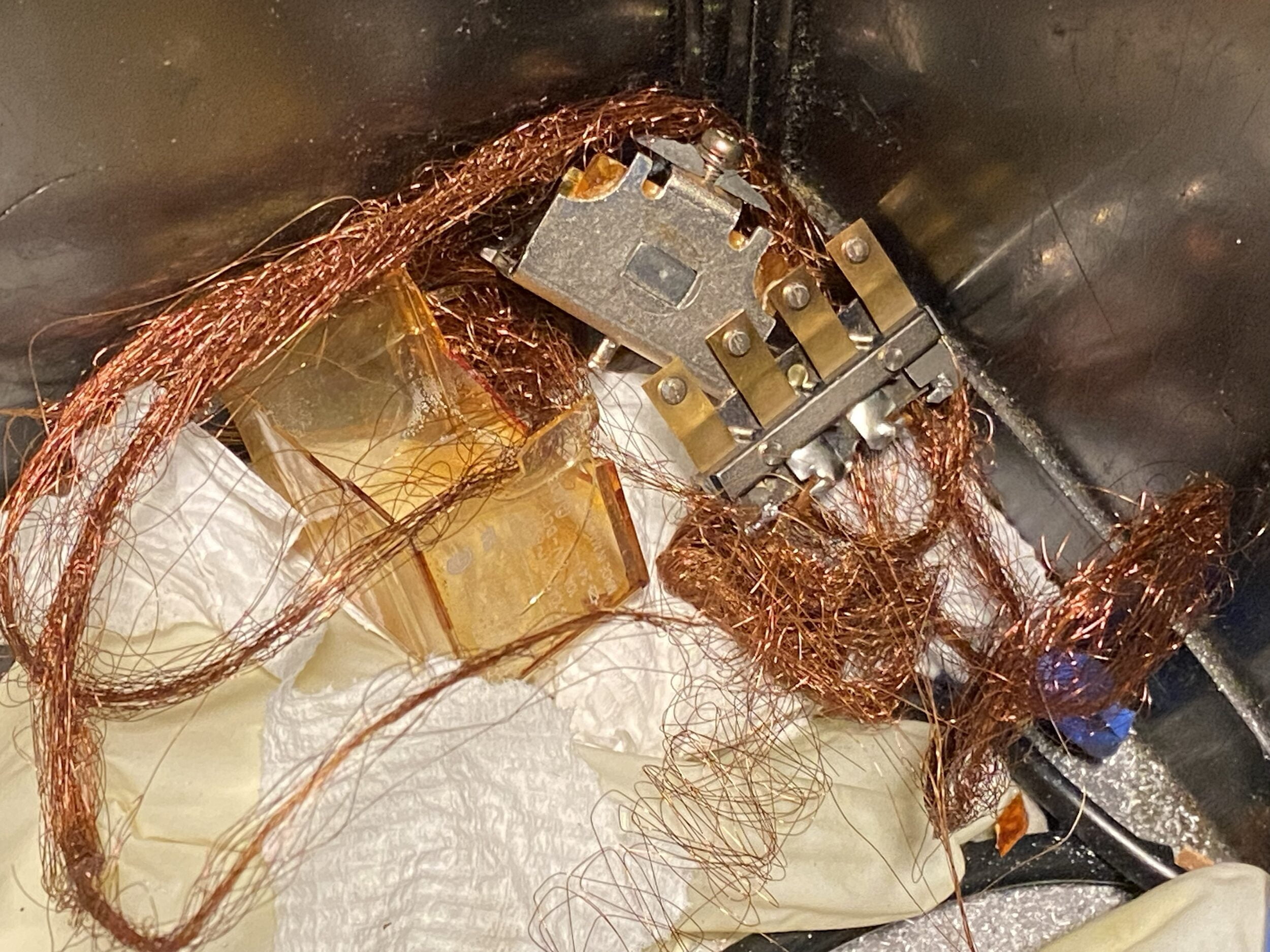
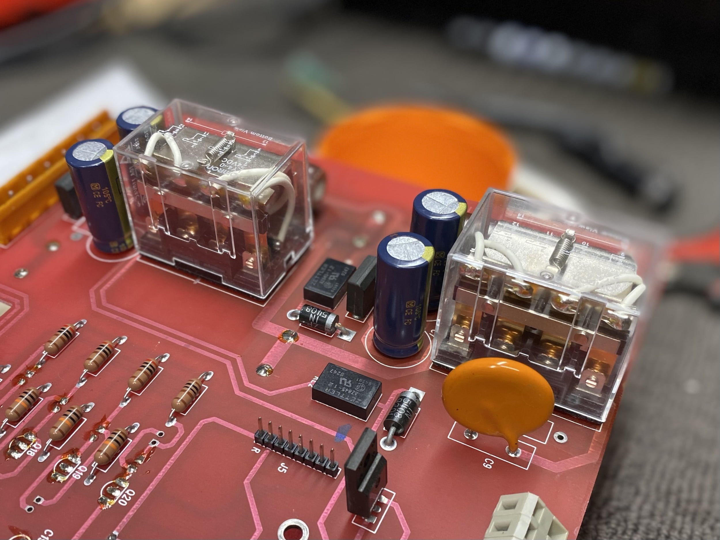
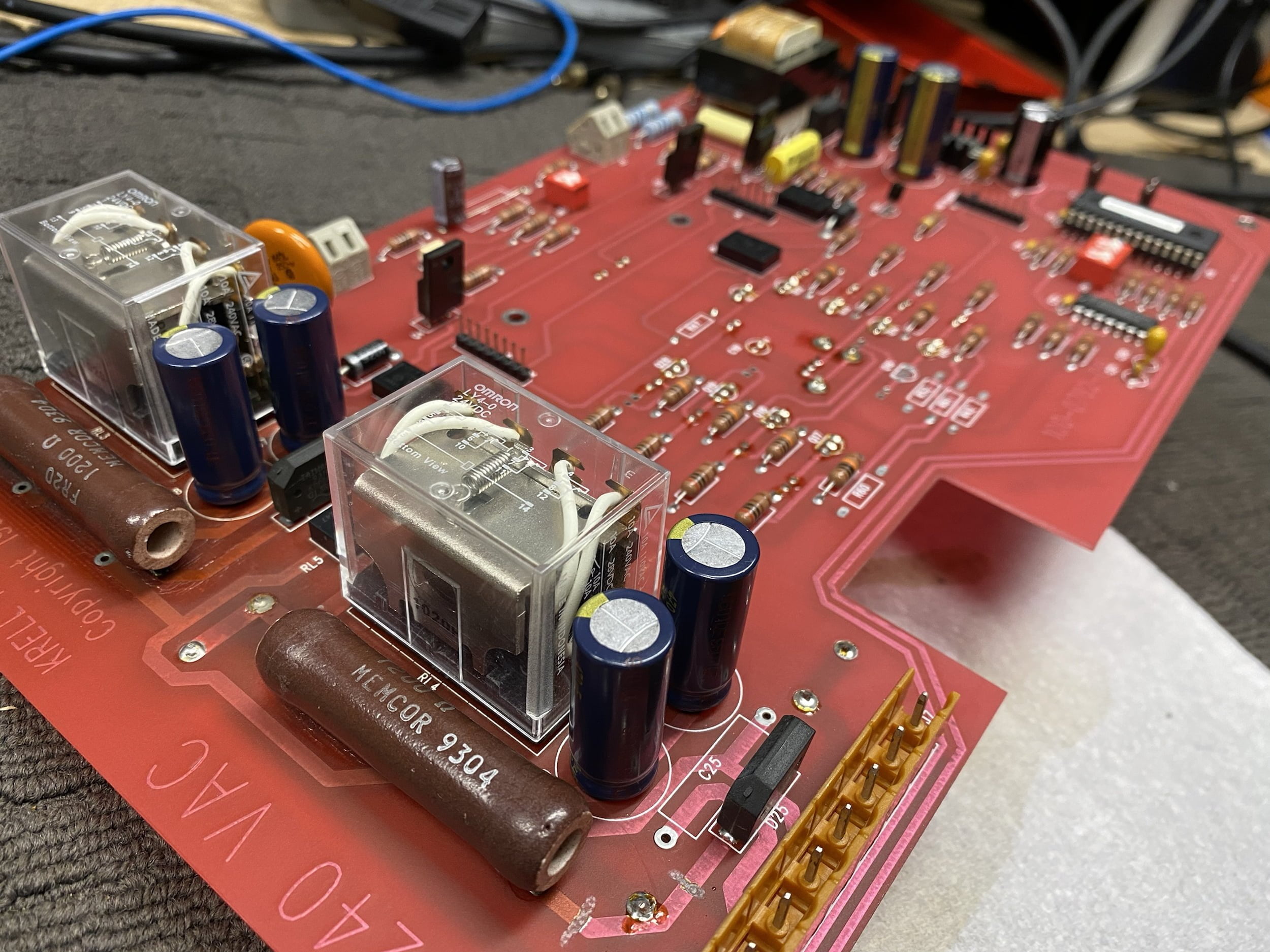
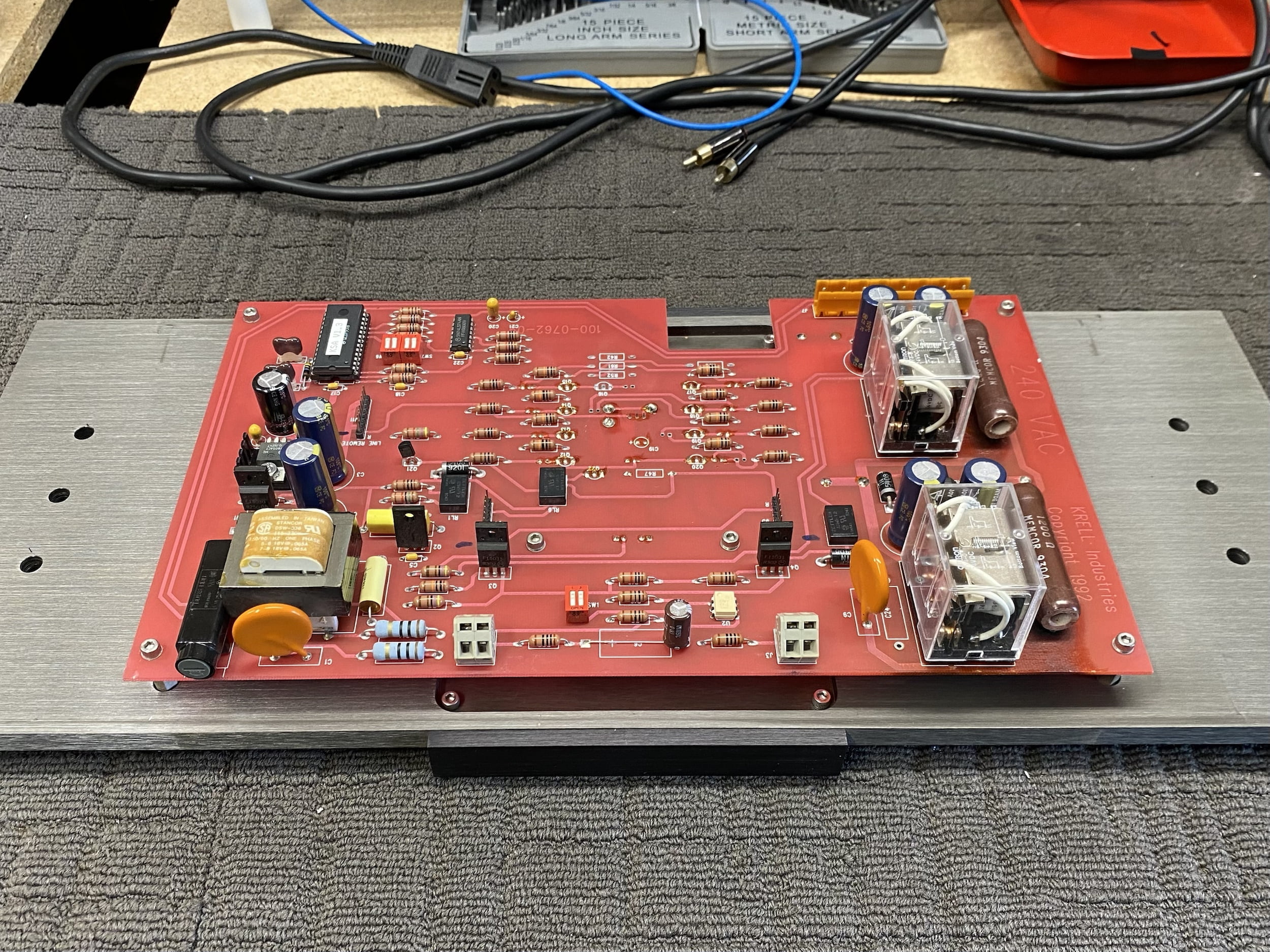
The control module, situated behind the front panel, controls the operation of the amplifier including soft-start, master/slave mode and some other stuff we won’t go into here. These control boards suffer over time from heat damage, especially around the inrush limit resistors and relays. In this case, the relays had really suffered and the owner had even attempted an ill-advised repair in this area. Time for new ones, and a total overhaul.
Power Supply Module + Further Diagnostics
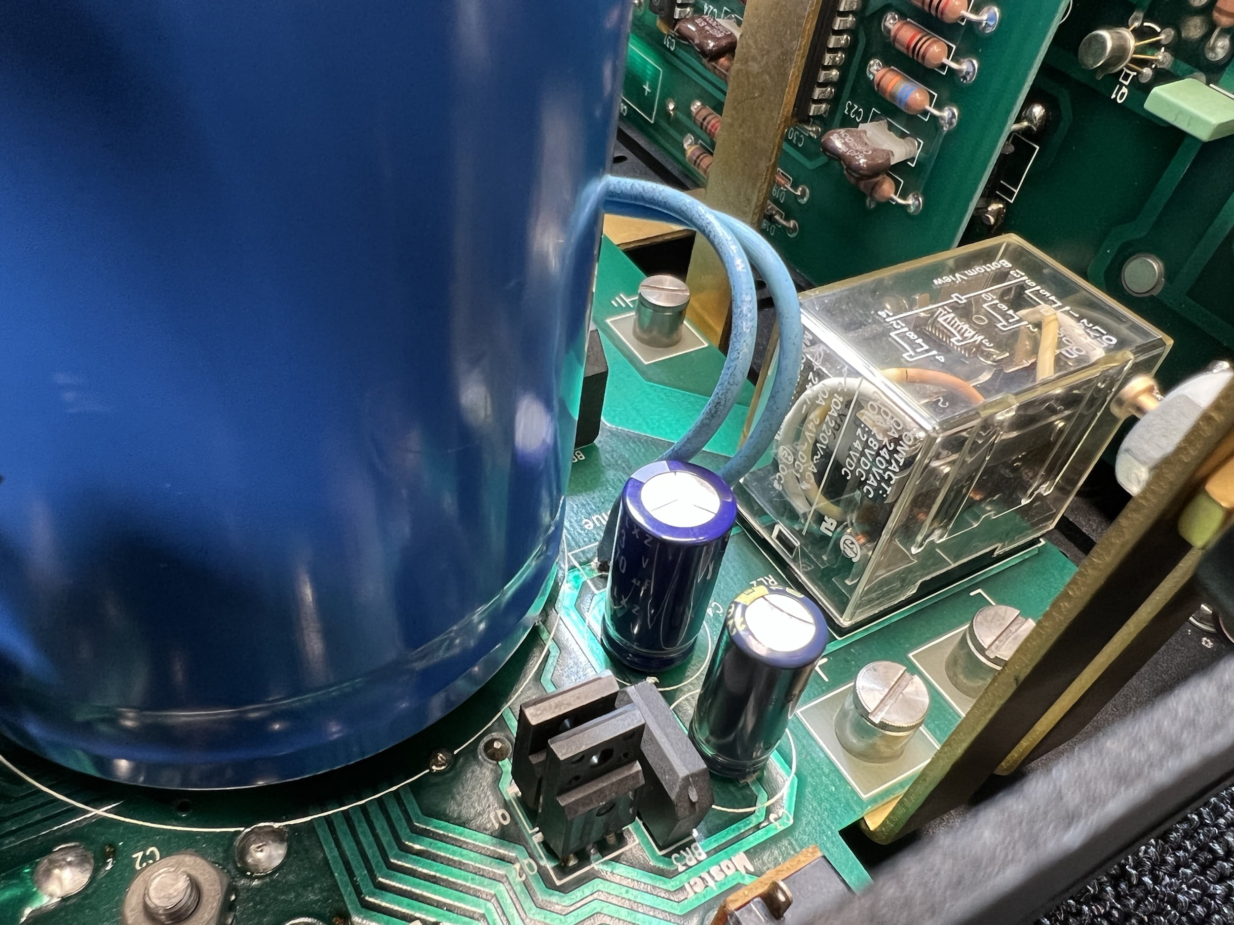
I reassembled this Krell KSA-100S twice. That’s because, after the first reassembly, testing revealed that after power-on, the amplifier only ran for around 30 seconds before shutting off again. There were some positive signs though: there appeared to be no high current faults and she powered on, with no smoke and no signs of distress. So far so good, kinda…
Further testing during the brief period she would run for revealed a DC offset at both outputs, before the protection relays. The amplifier was not coming out of protection, so this was the only way to measure that very important metric. Why is that important I hear you ask? Well, the amplifier protection circuitry will shut the unit down if it senses significant DC at the outputs, that’s what protection circuitry is for. If there’s DC, there’s a problem.
This was upsetting after all the hard work but it just meant more work was needed. Once I’d settled down, I tried to understand why the DC offset might be there, looking at the schems etc. Further testing revealed that one of the high current rails appeared to be low, actually non-existent. That would certainly account for the weird DC asymmetry.
I discussed the fault with a colleague and with Krell before going further. My feeling was a blown trace or maybe an opened diode bridge and both my colleague and the guys @ Krell agreed. I decided to tear it apart again and strip the power supply, thanks to Jason and Raymond and the Krell team who encouraged me to stick at this repair because it certainly grew tedious at one point!
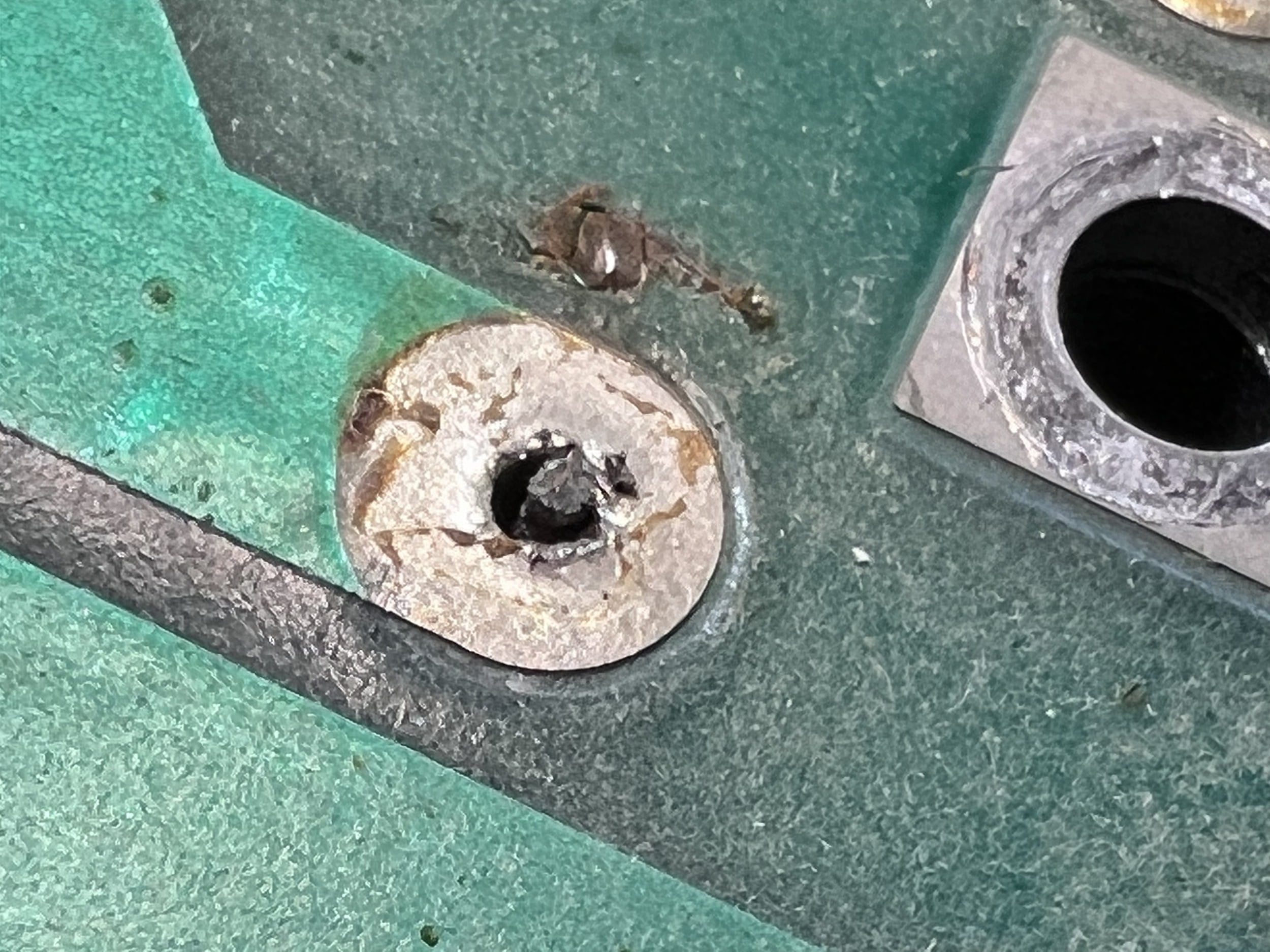
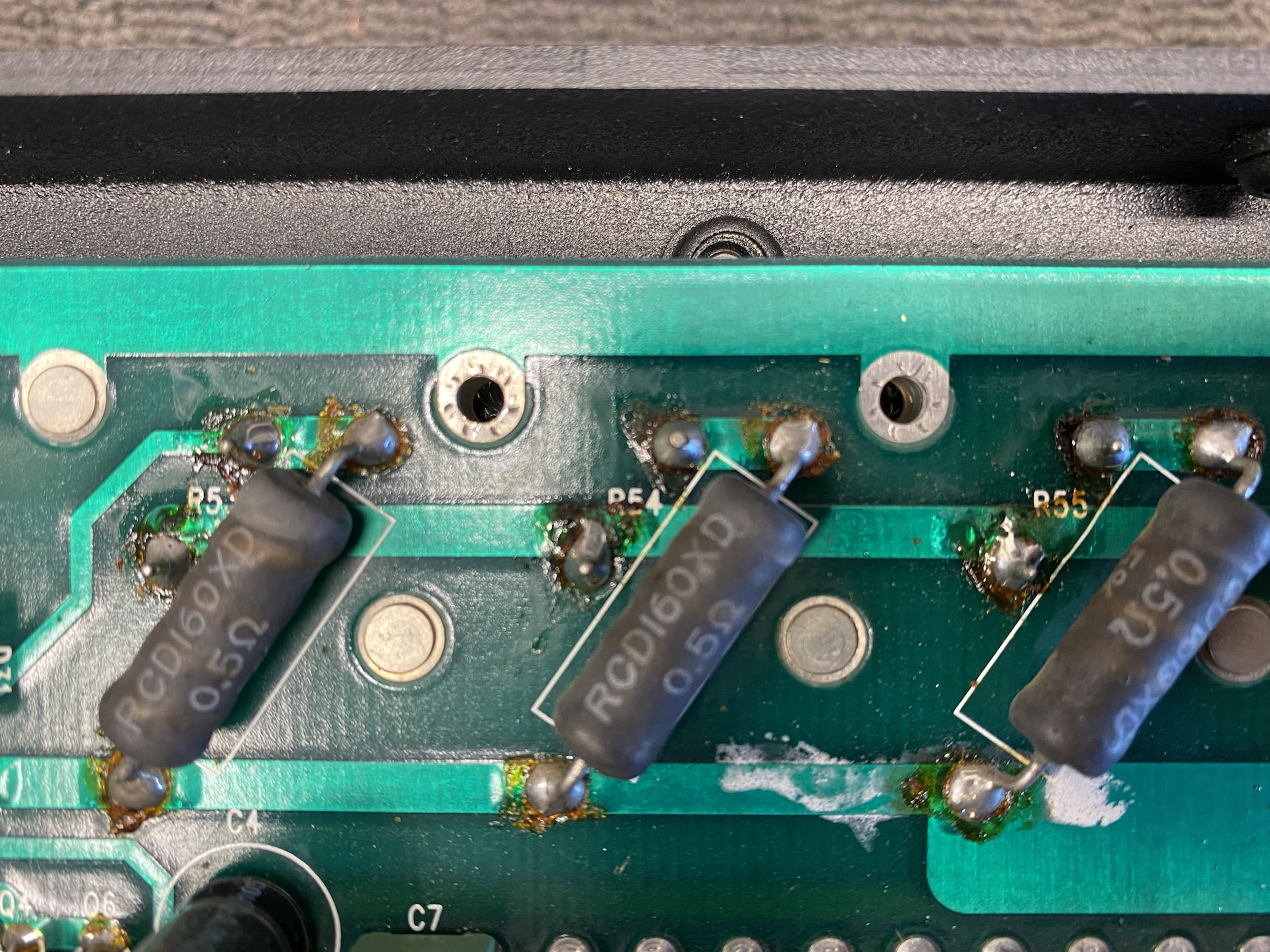
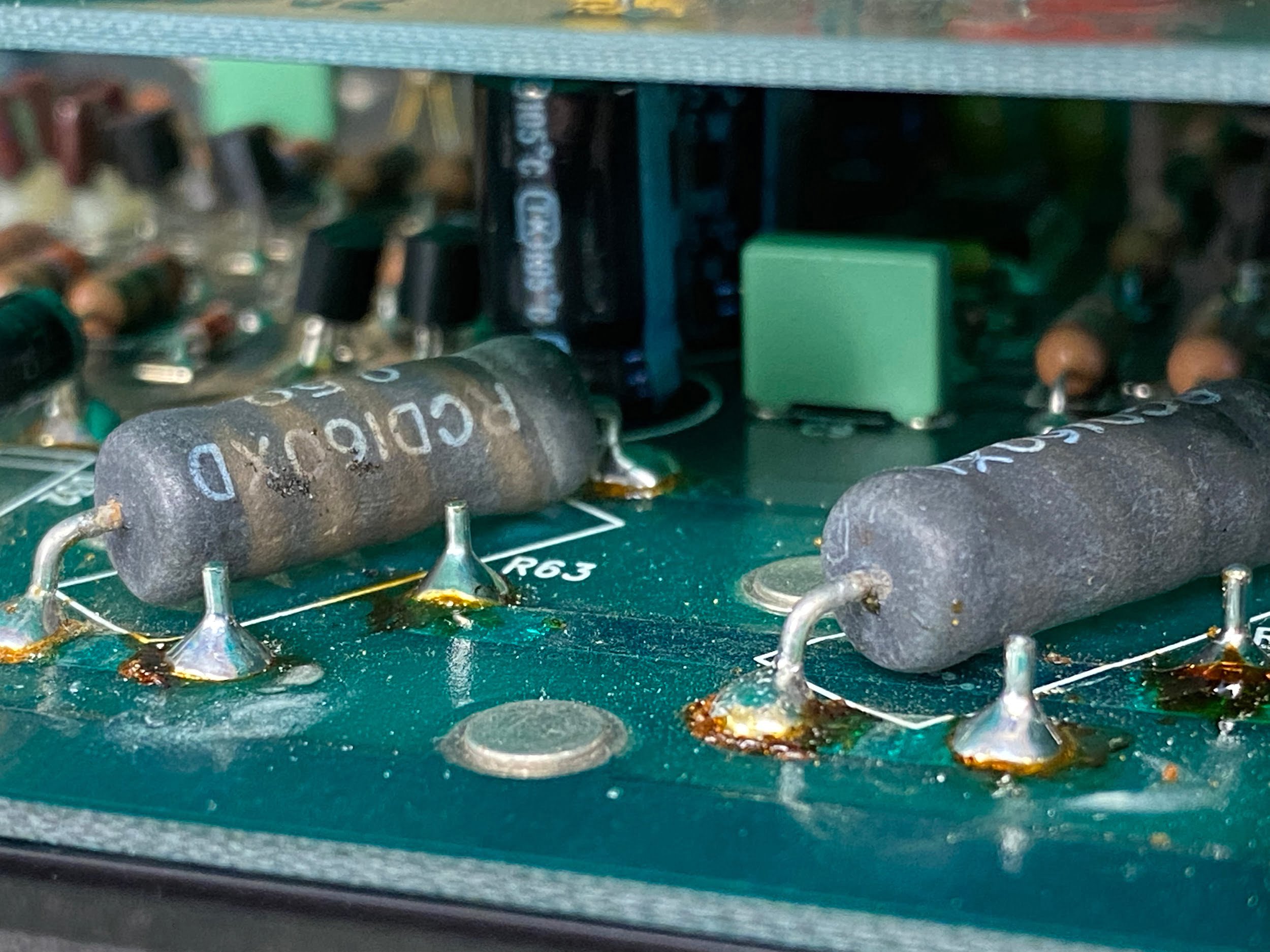
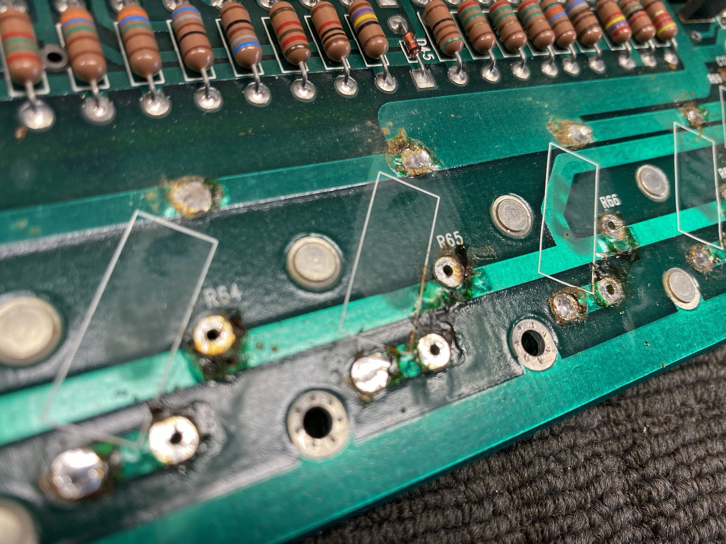
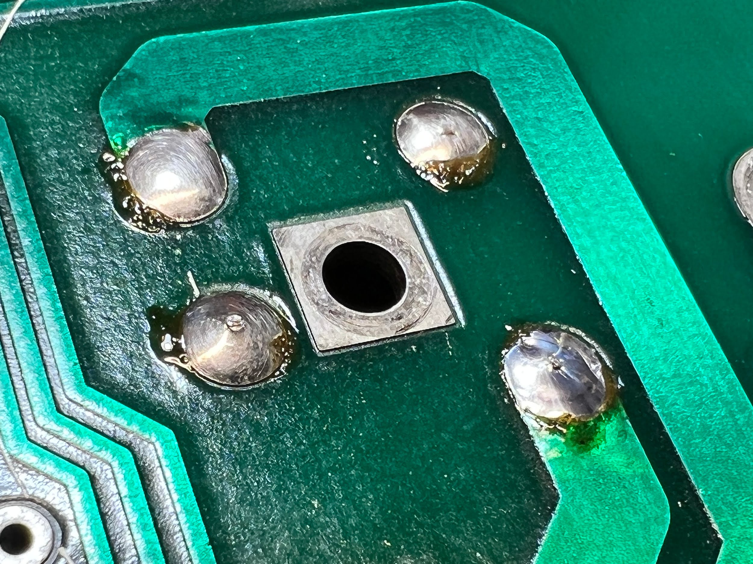
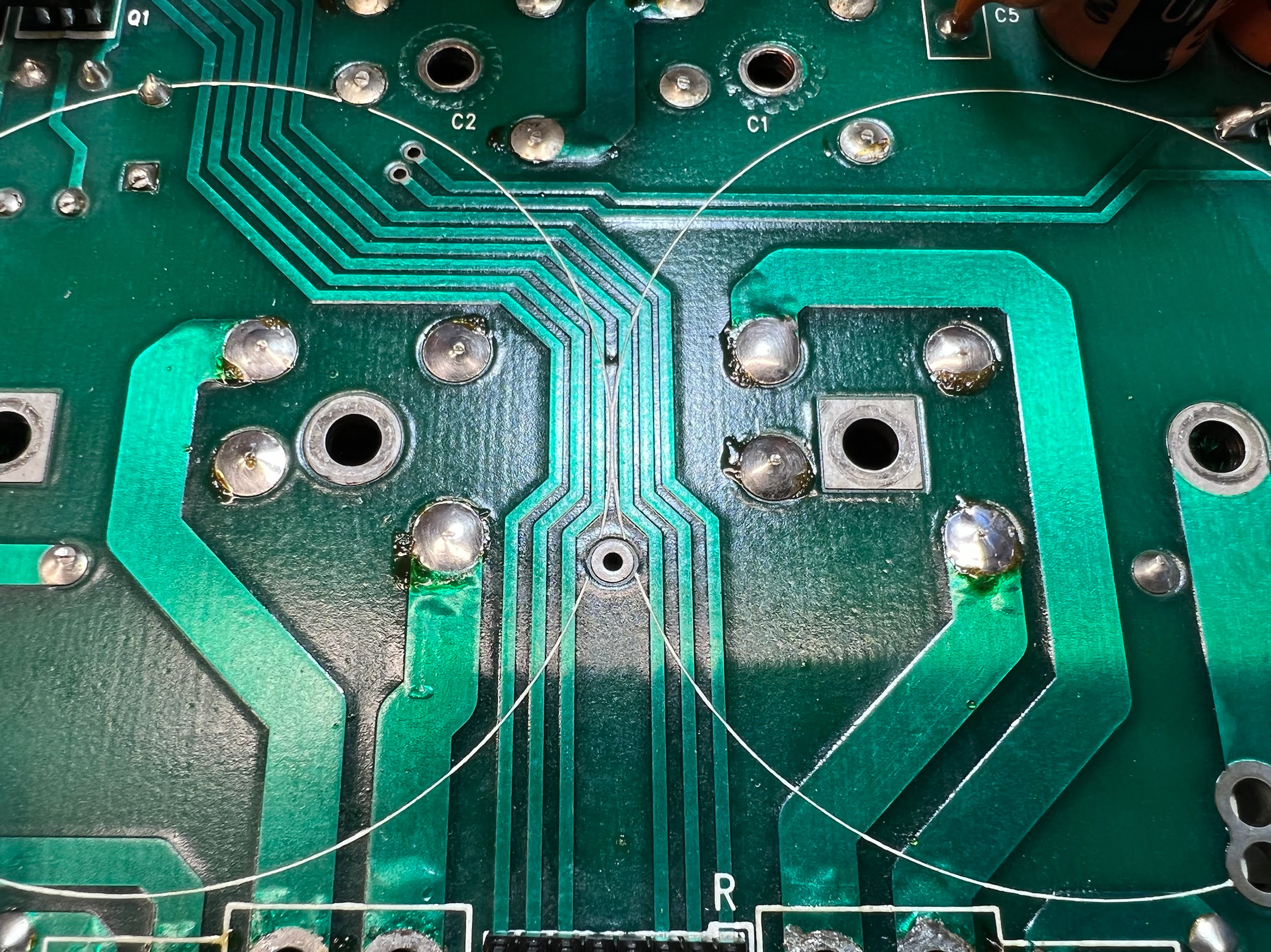
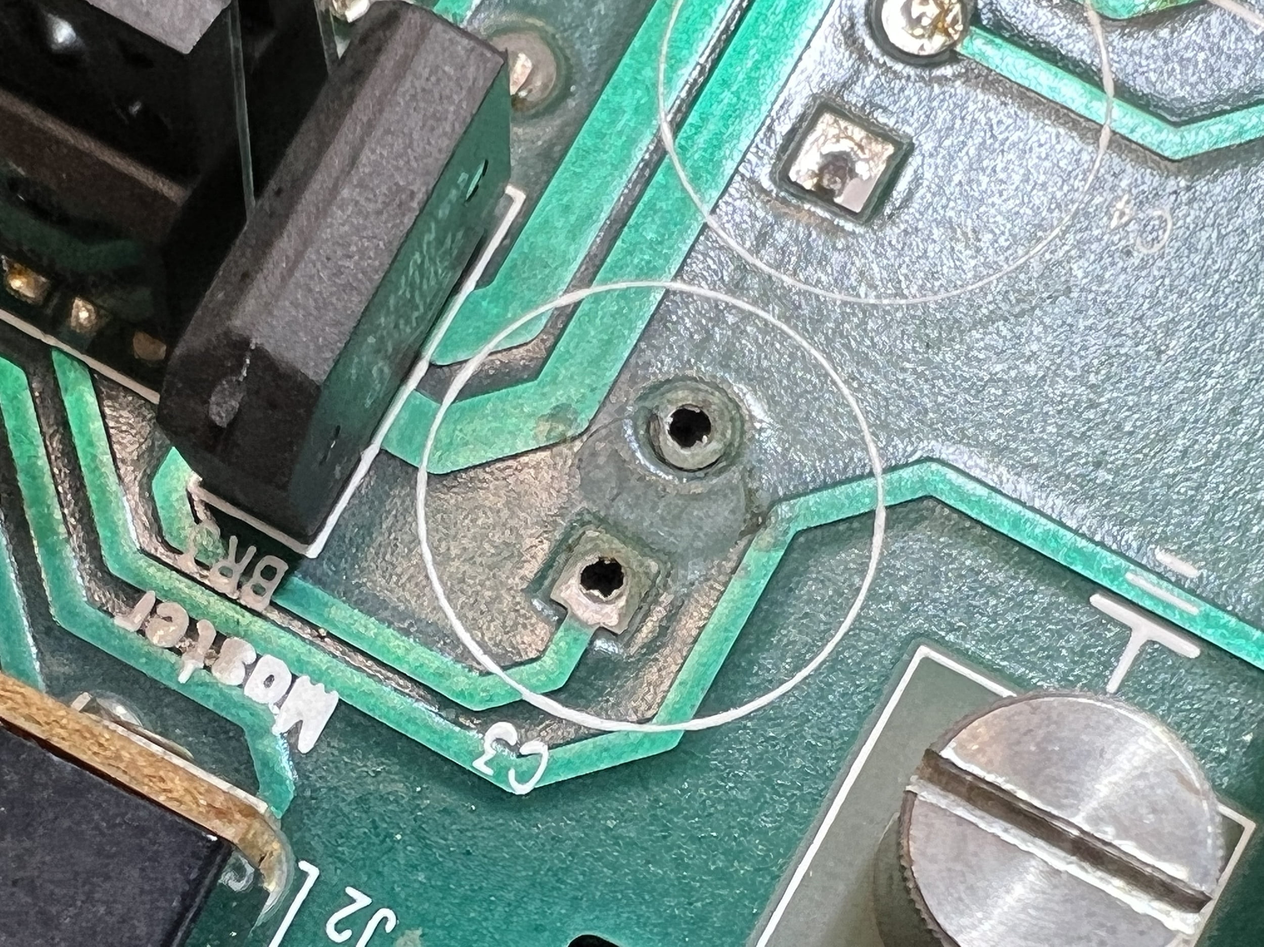
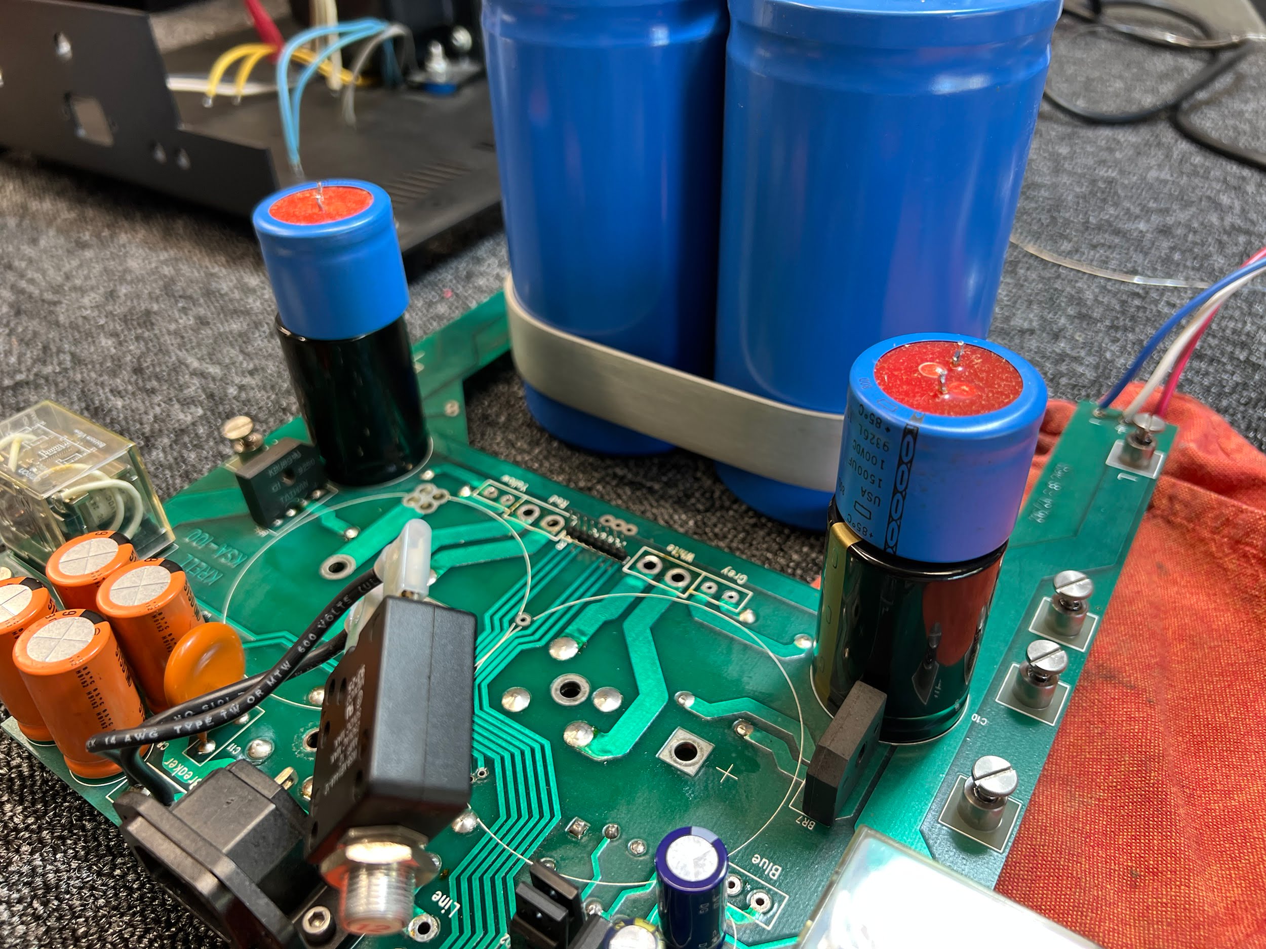
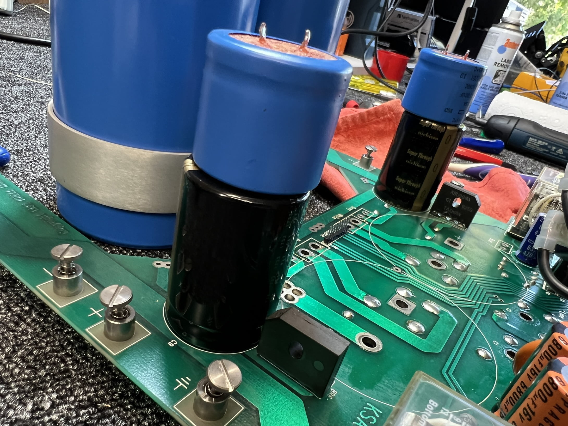
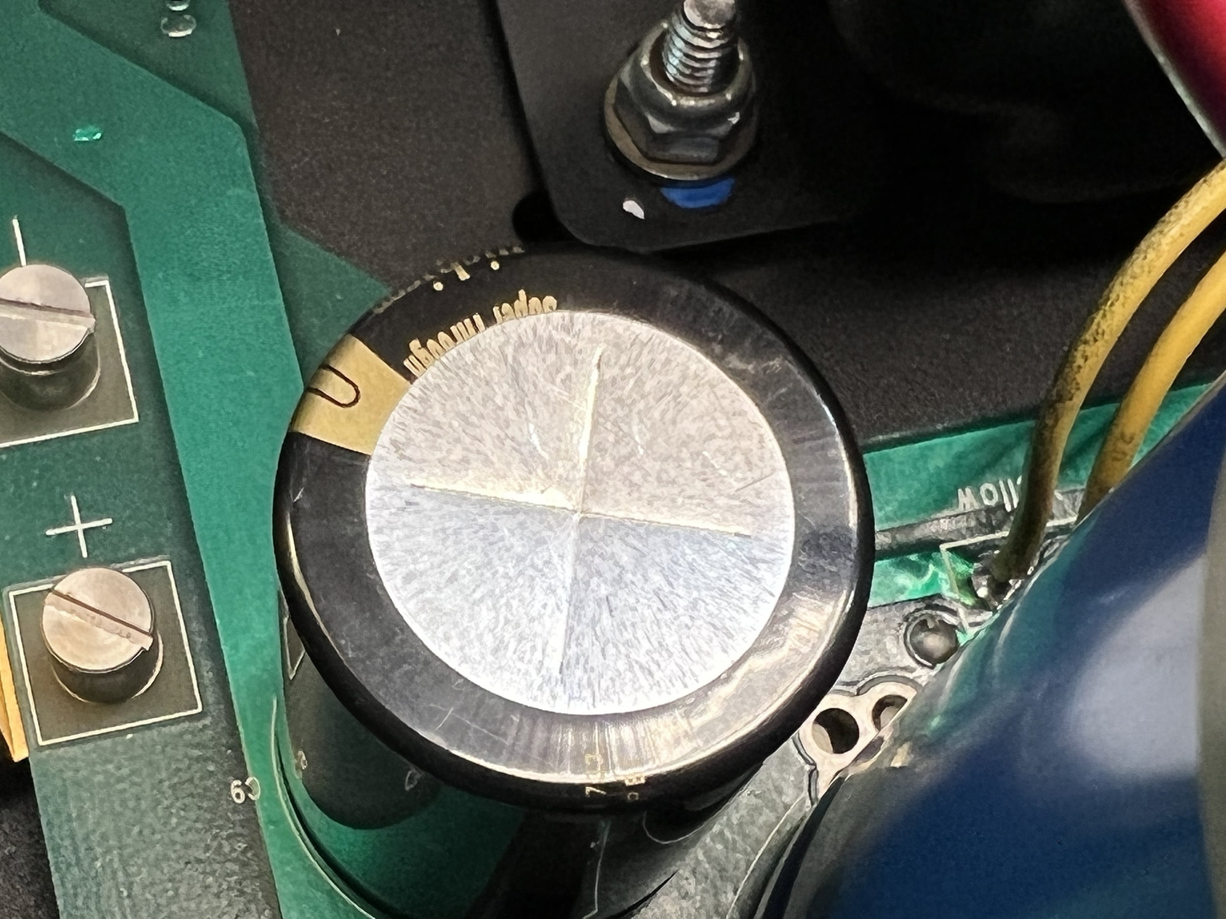
So, let’s comment here a little about what we see in this photo. This joint might look like it was never soldered, but of course, it was. It may have passed through a wave-soldering machine, I don’t know if these joints were hand-soldered or not but I’d suggest wave-soldered. These are heavy through-hole vias and pads, they wick away a lot of thermal energy and that can mean the initial soldered joint is marginal. I’d say that’s what happened here.
Over time, the joint heats and cools, and passes a ton of current. This creates more heat and gradually the joint weakens and cracks. Once that happens, joint resistance increases and flowing the relatively high currents seen here creates quite a bit of heat, creating localised vaporisation of the solder, until there is simply none left in the joint. I’ve seen this failure mode before. It truly looks like there was never solder here.
Repair involves thorough desoldering, cleaning and defluxing, prepping the material with the glass fibre pen, re-cleaning and then a high temp hand-soldered joint with powerful soldering iron and premium leaded solder. The joint will be good again for many years after that.
Miscellaneous
I always forget to add the details about the many hours spent cleaning connectors, trimming wires, testing components, neatening components dress, cleaning boards, and washing the chassis using my proprietary process. It’s partly because it’s so embedded in the way that I work, that it’s process work I don’t think about, I just do it.
That’s a mistake because I know from experience that it’s all the little stuff that comes together to make a really significant difference. That big orange front panel connector for example had a heavily oxidised main power pin. I measured it for resistance and it was bad, no doubt causing local heating and further degradation. I spent some time just on that pin, and on the connector in general.
The details matter, that’s the takeaway.
Results
After finding and resolving the hidden power supply problem I re-assembled the amplifier for the second time and briefly admired the final result. Hitting the power switch, I was thankfully greeted with the customary full LED ladder telling me she was running at full power, followed by the LEDs gradually extinguishing as power consumption dropped down to idle. It’s a curious quirk of these amps that they slam on to full bias from dead cold and it’s always a bit scary because you really need to let them do that to know if they will run properly or not. They won’t power up current-limited.
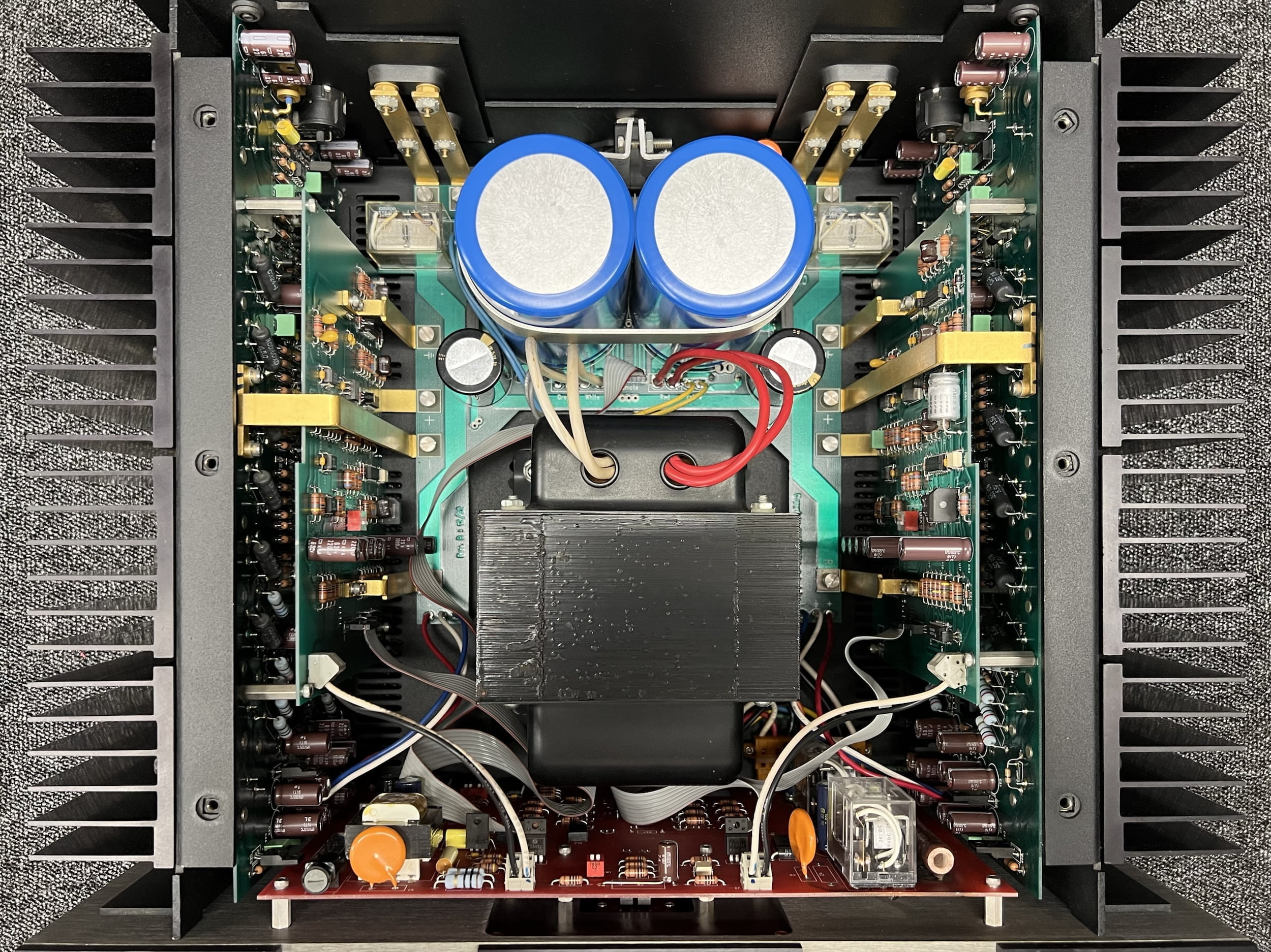
Her owner was extremely pleased we were able to resurrect this classic beast, with good reason. I was pleased to work on it but importantly, there aren’t too many places in the southern hemisphere offering this sort of service with this attention to detail and ability to repair these sorts of amplifiers, with tricky faults. Many people send their amplifiers back to Krell but you don’t have to. Best of all, Krell is kind enough to support the work I do here.
I’ve yet to hear back from the owner in terms of how the Krell KSA-100S sounds in his system, but it’s either incredibly good, or perhaps doesn’t receive the requisite spousal approval. Maybe it’s both?! Both this and the KRC-HR I worked on for him sounded fabulous after restoration and overhaul. Sometimes people get other gear whilst waiting for repairs like this though and that’s completely understandable.
Performance
Sonically, I’ve heard and worked on quite a few amplifiers from this series over the years and they all sound fantastic. Very strong, deep, taught bass, clean clear mids, airy treble, never fatiguing and always able to command control of the speakers they drive. This is only a 100 Watt per channel amplifier into 8 Ohms, so in terms of sound pressure levels, this must be kept in mind. But if you have power-hungry speakers that need a good ‘hand on the collar’ to control them, this is what you need, or something like it.
Compared to ‘affordable’ modern-day gear, this is in a different universe. Anyone who tells you otherwise simply doesn’t know what they are talking about and that wouldn’t be uncommon! Compared to really expensive modern gear, this is better made than almost all of it. It kills Krell’s modern gear.
Bang-Per-Buck
Let’s chat briefly about bang-per-buck owning and restoring an amp like this. I often tell people how undervalued equipment like this is, even now. To replace this with new, you’d need to spend maybe $25K to $50K AUD, to get like for like.
Of course, you can buy a 100 W per channel amplifier for a couple of grand, but this ain’t no regular 100 Watt amp, friends, nor does it sound anything like what a few grand will buy you, new. As soon as I plugged her in and listened to a few tracks, even in the sub-optimal workshop environment with the Yamaha NS-10Ms, I could hear the difference between an amplifier like this and a regular amp. Do you see where am I coming from with this? You don’t want Bluetooth in your amplifier, or a DAC. Trust me on this and ask me why in the comments if you don’t know.
Generally speaking, you don’t do the sort of work we’ve just done to this beauty to try to make the money back in a quick sale. You might do a minimal repair in a case like that, this wasn’t that sort of job. Work of the type we’ve done here is typically reserved for those wanting to keep their equipment long-term and get the most out of it. Think of it as an investment in your cherished hi-fi equipment.
It’s like rebuilding a car engine. It may not add significantly to the sale price because people expect it to run. It will significantly improve the selling price though if the vehicle or amplifier doesn’t run. A repair and rebuild is a no-brainer in cases like this. Either way, what it will do is make your car/amplifier/whatever perform better than it perhaps ever has and you really can’t put a price on that.
Amplifiers like this are barely made now, so for the few thousand dollars, you might pay to obtain one, understand that it’s one of the all-time great values in hi-fi. This is indisputable, whether people understand it is another thing, but the value is unquestionable.
I mean, it’s either a Krell KSA-100S like this or a NAD C298 for example… They are simply not from the same universe. One is a memorable, legendary piece of gear still highly sought after, the other isn’t. You pay your money…
On that note, as always, thanks for reading and you are welcome to get in touch if you have a Krell amplifier you’d like me to take care of for you.
Discover more from LiQUiD AUDiO
Subscribe to get the latest posts sent to your email.

Fantastic job again Mike. Your write ups are confirming that sharing your repair philosophy is the right thing. We might scare a few clients off when we tell them how much time and effort is put into bringing their “loved ones” back to life, but the pure joy of the clients getting their units back better than factory is worth it! Now I can start my day (classic Dual day today) with a smile on my face.
Thanks Idar, much appreciated and yes I agree, it’s really important that people know that this is intensive, technical work. Worth it though!
Lovely to see a beautiful beast restored and reinvigorated… this era of Krell is sublime…
She is a beauty.
Most modern amps under 20k won’t get close to the sound of this.
Thanks Simon, agreed on all counts. Really hoping you are well?
Superb work and very educational. Thanks!
Best Regards
Matt McNulty (from the UK)
Always a pleasure, thanks Matt!
Awesome workmanship!!! What process do you use to wash the boards?
Thank you, much appreciated! I’ve developed a proprietary cleaning process but, for commercial reasons including other businesses who visit and copy ideas, techniques etc, I’ve become a bit guarded about some of the details of my work.
Hi Mike,
Great restoring work and I know what I am saying. I did the same work about 2017 because a lytic capacitor exploded inside. If you want I can send you pictures you can use them as you wish. I am not able to write up an article as you did.
During restoration of my KSA100-S, I contacted you because I needed help to unlock the Neutrix connector from the panel and I got help from you, do you remember? I also contacted Krell and they gave me all the support I needed. This Krell is a piece of art,
Keep doing and sharing your work Mike,
Vincent from France
Hi Vincent, thanks for sharing your experience and glad I was able to be of some help with your repair! You are welcome to send a couple of pics, I can’t guarantee I can use them, but will if I can.
Hi, I have a pair of Krell FPB-450MCX monoblocks. The right hand side one hums. Is this dried out caps? Or something else? Grounding loops, what? I’m not sure where to begin.
I have an electronics background (from years ago though – moved to networking), but if I can simply pop old components, clean up boards and whatnot, I’d be happy to do it myself.
What say you all?
Hi Erik, thanks for your question and nice amplifiers! I hate guesswork and it’s unhelpful in situations like this, so I’d need these in front of me for assessment, testing and fault diagnosis, difficult if you are not Perth-based. There are many possible fault scenarios but they all require the same hands-on, logic-based approach to resolution, more on this concept here: https://liquidaudio.com.au/faq/my-rare-and-valuable-amplifier-has-failed-how-much-will-it-cost-to-repair/. Amplifiers of this age are long overdue for a comprehensive, well-executed overhaul. Work may have been done but it is often poorly executed, causing more problems than it solves, so this can be a good place to start. These are complex amplifiers so proceed with caution. You need everything in place to tackle something like this. If you haven’t fixed amplifiers like this and don’t have service data, tools and the right parts to hand, I strongly suggest taking this to a specialist repairer.
Hi Mike. Great job you did on that KSA 100S. I have a KSA 300S that has the same burn marks on the control module board from the two 1200 Ohm Memcor resistors, and I fear that the heat from those resistors will be the end of the board some day. Do you have a suggestion about how to improve/change the layout? Maybe some kind of heatsink that could be attached to the resistors? Cheers
Hi Flemming, thank you and yes these resistors can be a problem. The trick is to help them to dissipate heat as effectively as possible. Re-working the soldering to improve lead-to-pad conductivity helps as these joints degrade over time. You could also replace them with even higher power dissipation parts. You definitely don’t want to cover them with heatshrink or anything like that though as this will reduce their thermal performance and make the problem worse. EDIT: see my apology to Flemming next, he definitely didn’t say heatSHRINK!! 🙂
Thank you for your response. God idea regarding the resoldering. I agree about not covering the resistors with heatshrink:) But i wrote heatsink.. Something that might be able to transport the heat away from the board. But it might be easier to replace the resistors with higher power ones as you suggested. Cheers
Hi Flemming, my apologies, I should have read your comment more carefully, this is unfortunately what happens when you try to work and reply to comments etc whilst away on holiday! Yes, you could in theory attach a heatsink and it may help lower thermal impedance and therefore improve heat dissipation. I think higher Pd rated parts are a better idea in this case though.
Morning Mike. I have a MF AMS 100. I had a Krell KSA 300s before that. I loved my Krell and I also love my AMS 100 but for different reasons. the Krell had the slam but the AMS had the warmth and transparency. I’ve had the AMS for about 8yrs now and it’s never missed a beat. I am in Sydney but it would be interesting to know how to make the MF a master piece.. I loved reading your article.. Anthony
Hi Anthony, thanks for your question and I’m glad you enjoyed this one. I have to write up a Krell KSA-200S article but it’s such a big job that I keep putting it off! The KSA 300S and AMS 100 are both beautiful amplifiers, for different reasons. I’ve just finished repairing another MF AMS35i, you might enjoy this article about a previous AMS35i repair – https://liquidaudio.com.au/musical-fidelity-ams35i-class-a-amplifier-repair/ – and I have an MF M3 Nu-Vista integrated with me for repair and improvement. Like all MF gear, MF took an approach to building this AMS series that leaves plenty of room for improvement, mostly around parts and build quality. These improvements are something I focus on and whilst I’m absolutely full right now, looking at your amplifier down the track might well be possible. Stay in touch if this is something you’d like to discuss.