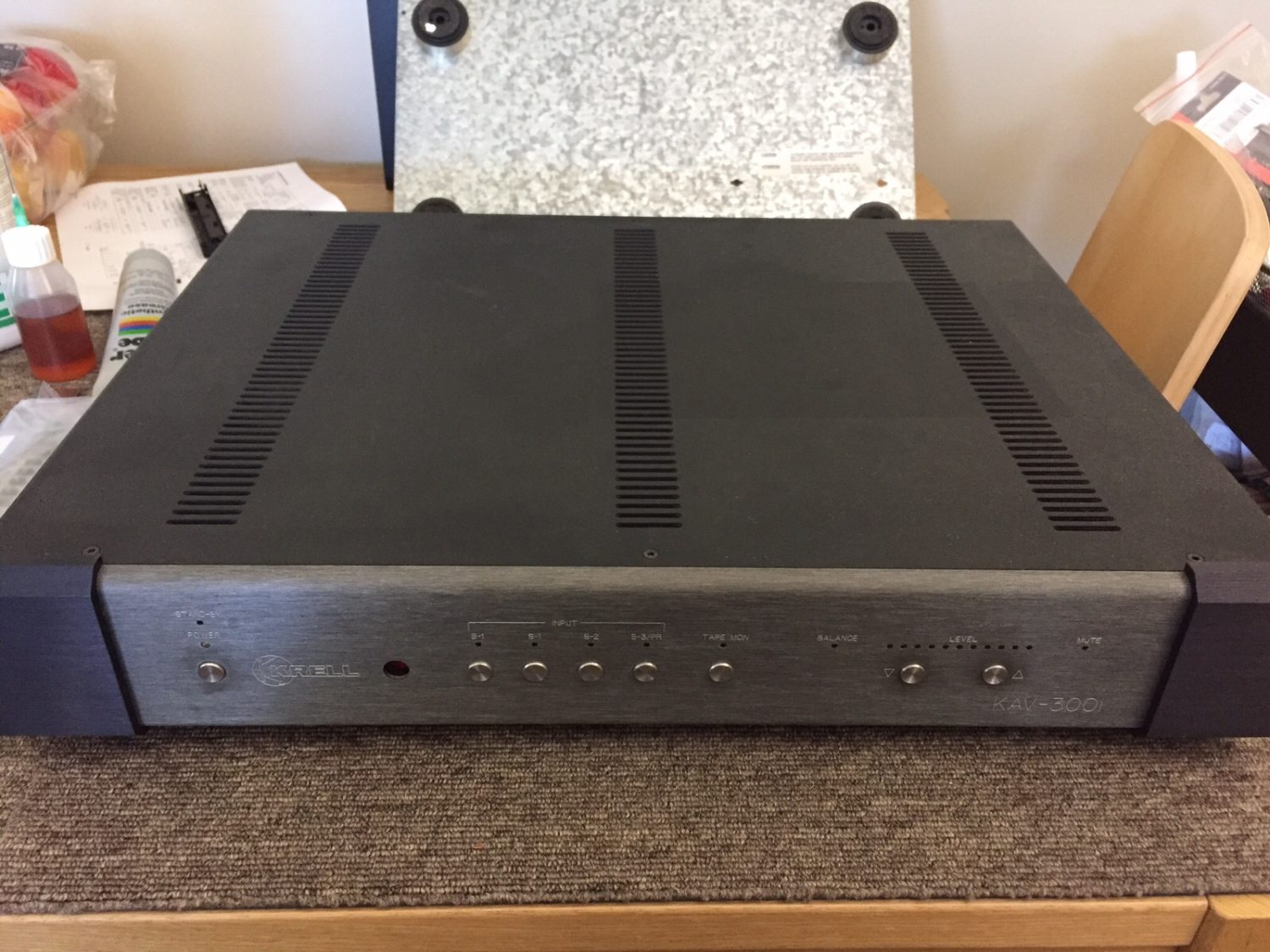
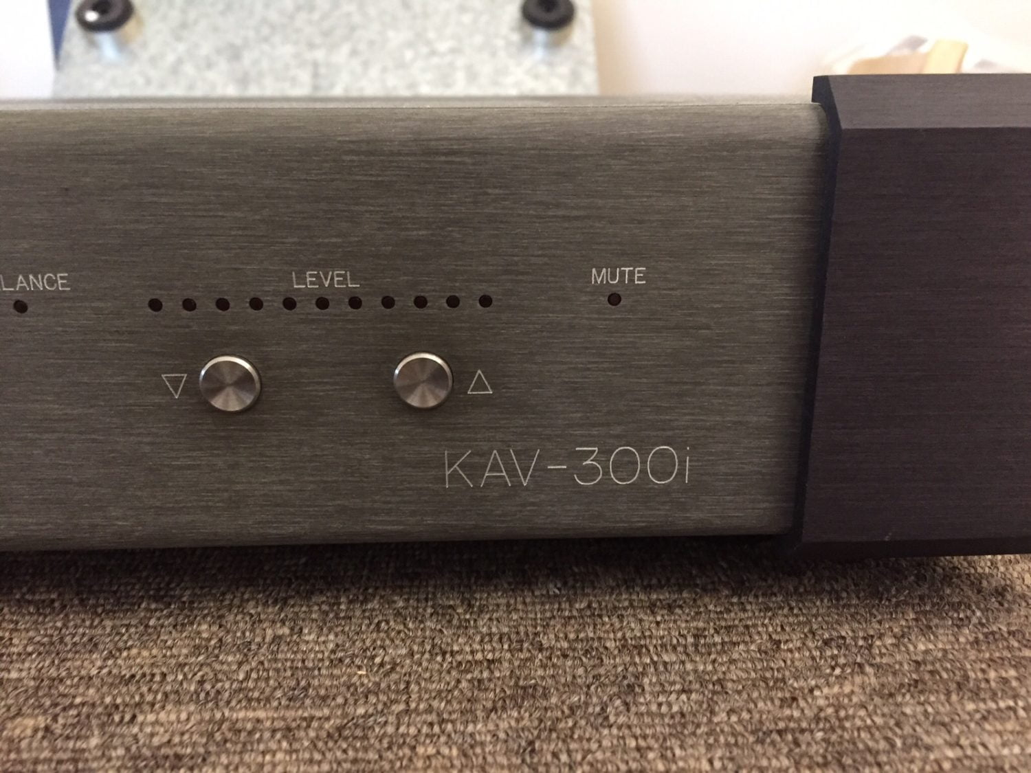
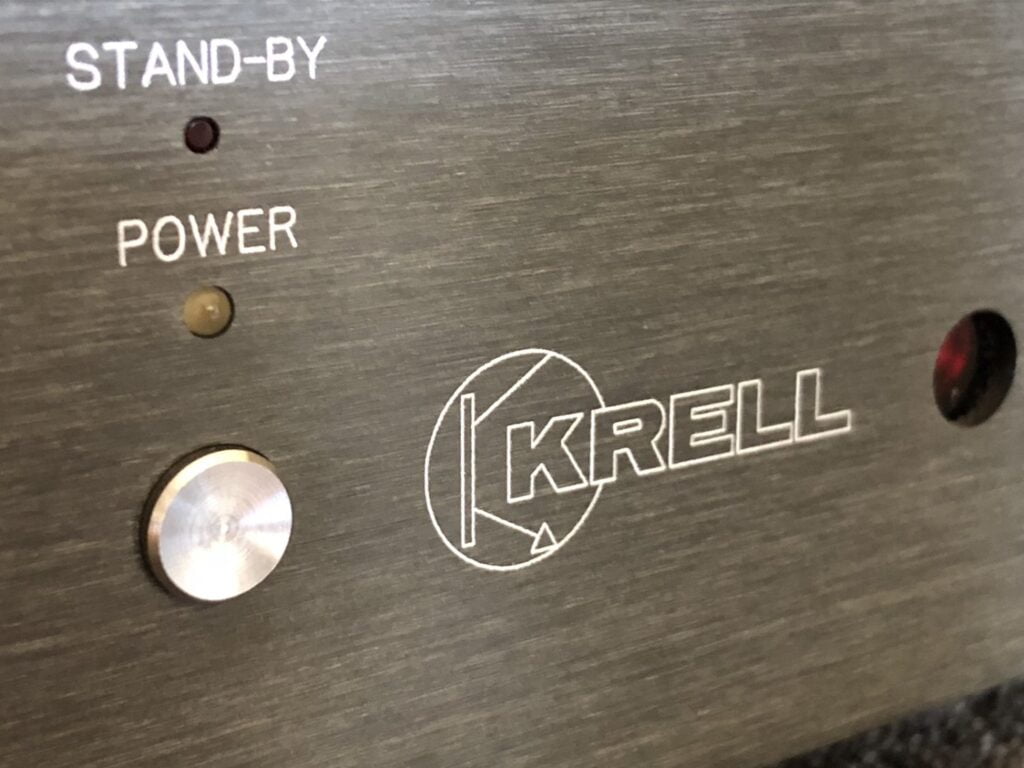
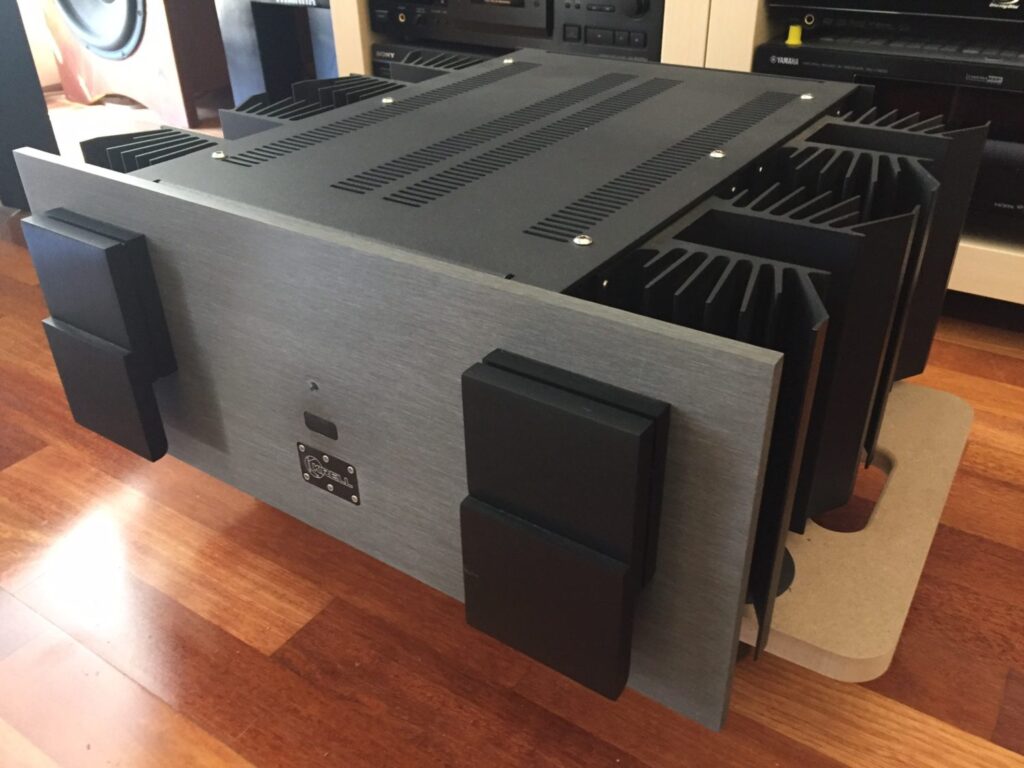
I’ve just repaired and restored this lovely Krell KAV-300i integrated amplifier. Read on to find out what makes the KAV-300i such a superbly engineered amplifier.
Krell still proudly builds amplifiers and other high-end gear, from their base in Orange, Connecticut, USA. Established in 1980, they set about manufacturing a range of really different hi-fi equipment, aimed squarely at the top end of town. The KAV-300i is part of the more affordable range of Krell gear from this period.
All Krell gear that I’ve had the pleasure of working on is superbly well-engineered, well-built, and utilising grade components that you’ll see in consumer-level equipment. This, of course, means it wasn’t (and still isn’t) cheap and that’s where the KAV line came in.
The KAV-300i
Krell released the KAV-300i, as far as I can tell, in around 1995. It has the same distinctive build and materials as seen in amps like the legendary KSA-150, that I owned and restored. That means it’s carved out of blocks of gorgeous anodized aluminium and held together with stainless steel fasteners. I’m not kidding. You couldn’t build it better if you tried.
The difference here is that everything is downsized – capacitors, heat-sinks, and ratings are smaller, as is the 2RU chassis. Compared to my old KSA-150, with roughly the same power output, the KAV-300i is diminutive.
This, of course, means that the KAV-300i cost less to make and was affordable for many more folks. There are still many of them around due to the superb build quality. They really don’t build much like this anymore. This particular KAV-300i matches her power amplifier partner, the KAV-150, both owned by my customer and here for service and repair.
Krell KAV-300i Specifications
Courtesy of Hi-Fi Engine
Power output: 150 watts per channel into 8Ω
Frequency response: 1Hz to 100kHz
Total harmonic distortion: 0.3% (trust me, wildly pessimistic!)
Signal to noise ratio: 95dB (line)
Dimensions: 475 x 387.5 x 92.5mm
Weight: 11.4kg
Accessories: remote control
Year: 1995 – 2000
Stereophile wrote a great review of the KAV-300i, definitely worth a read if you are looking to get one of these.
Restoration
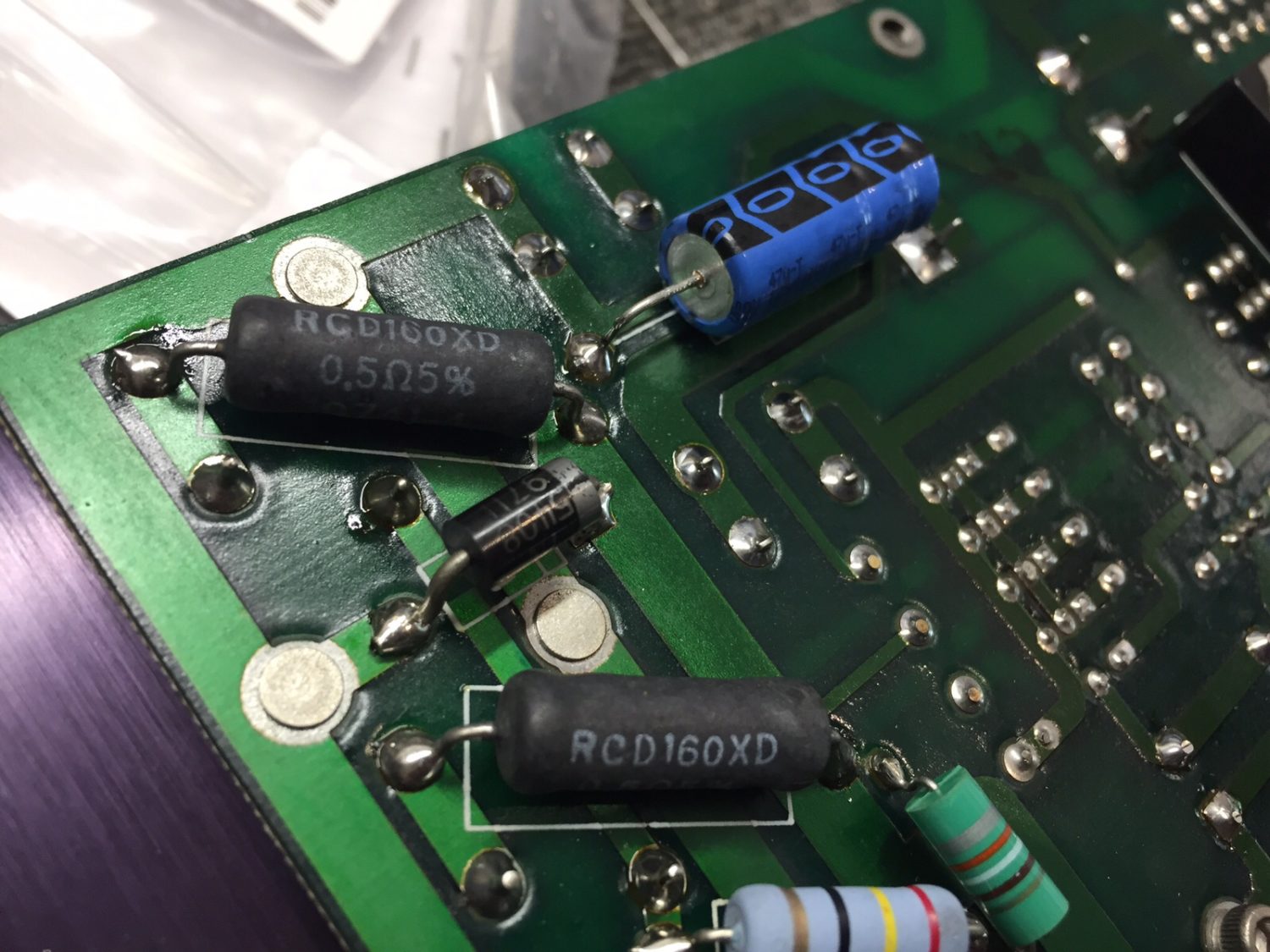
OK, let’s get down to it. This KAV-300i was in original condition which is great, but she was misbehaving. The main fault was distorted audio. I found a number of issues with this unit, mostly related to capacitor aging. The unit also exhibited issues with the board-to-board pins and pin header connectors. There were also a few dry joints for good measure.
Krell has been very kind to me over the years, assisting me with service documentation, where they have it and are happy to release it. A big thank you to Patrick @ Krell because, without that support, working on gear like this is more difficult.
Stripping, Cleaning
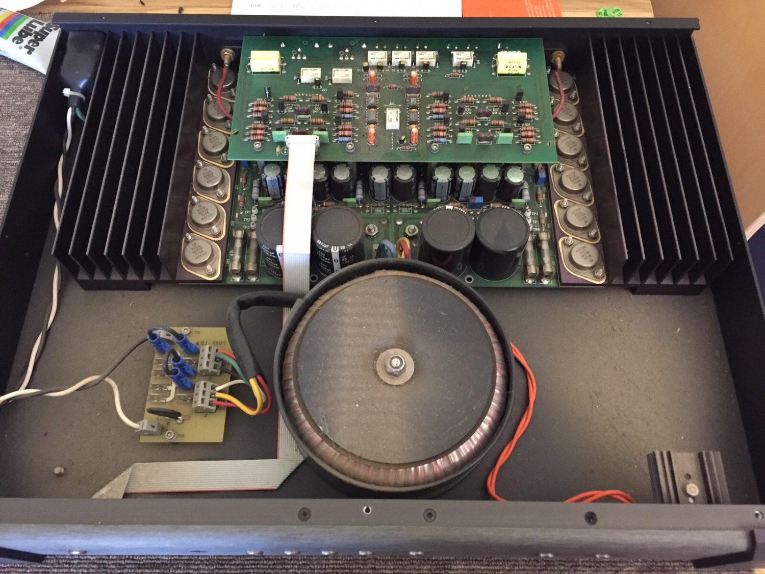
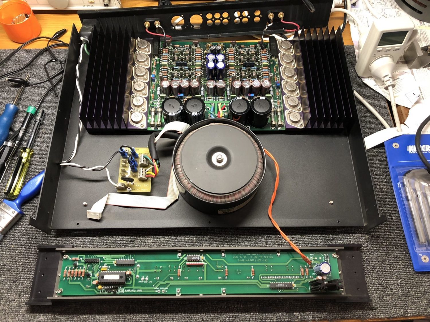
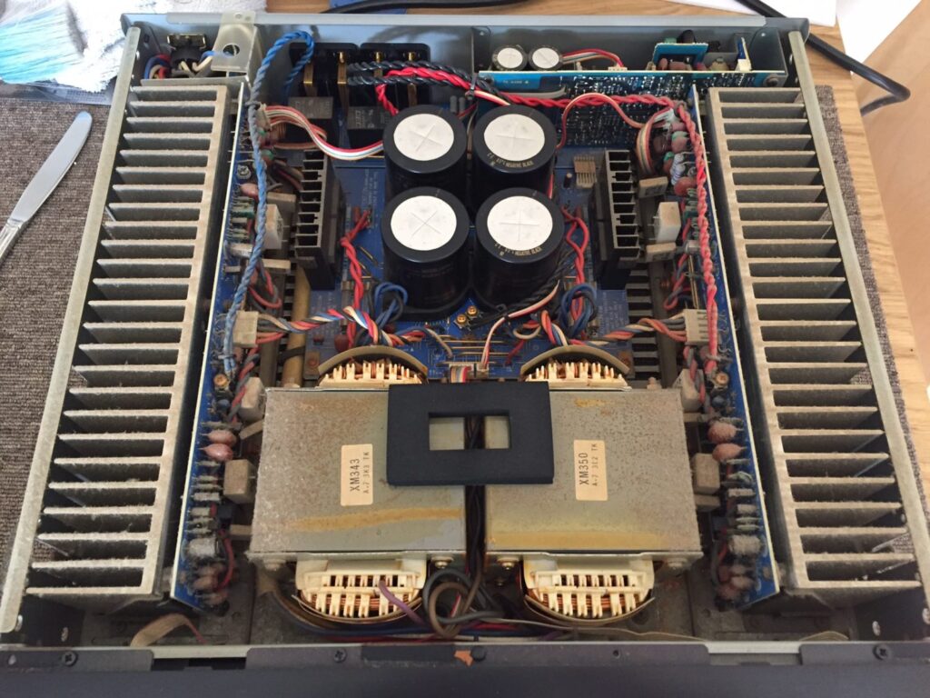
As always, I start with disassembly, inspection and cleaning.
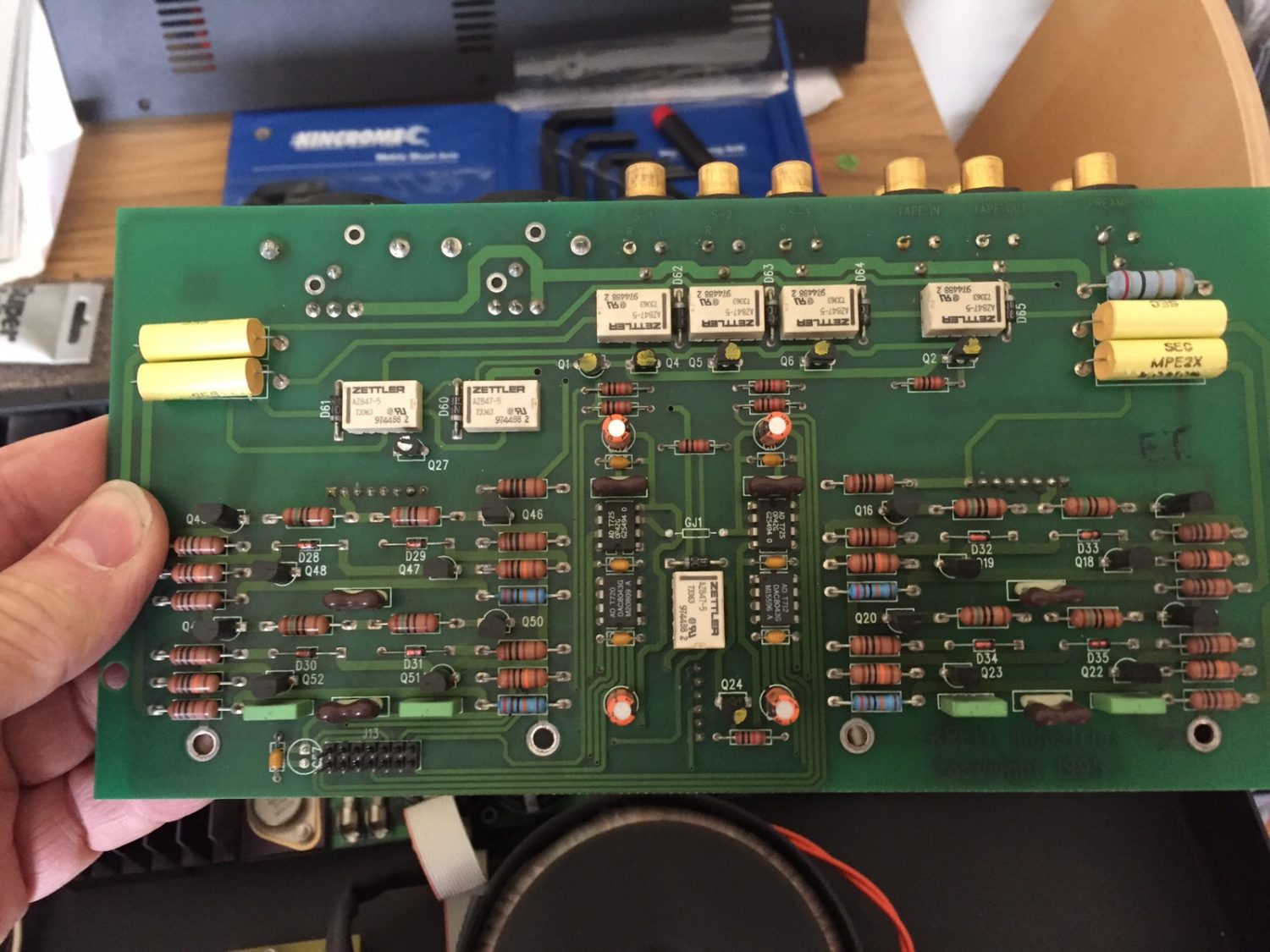
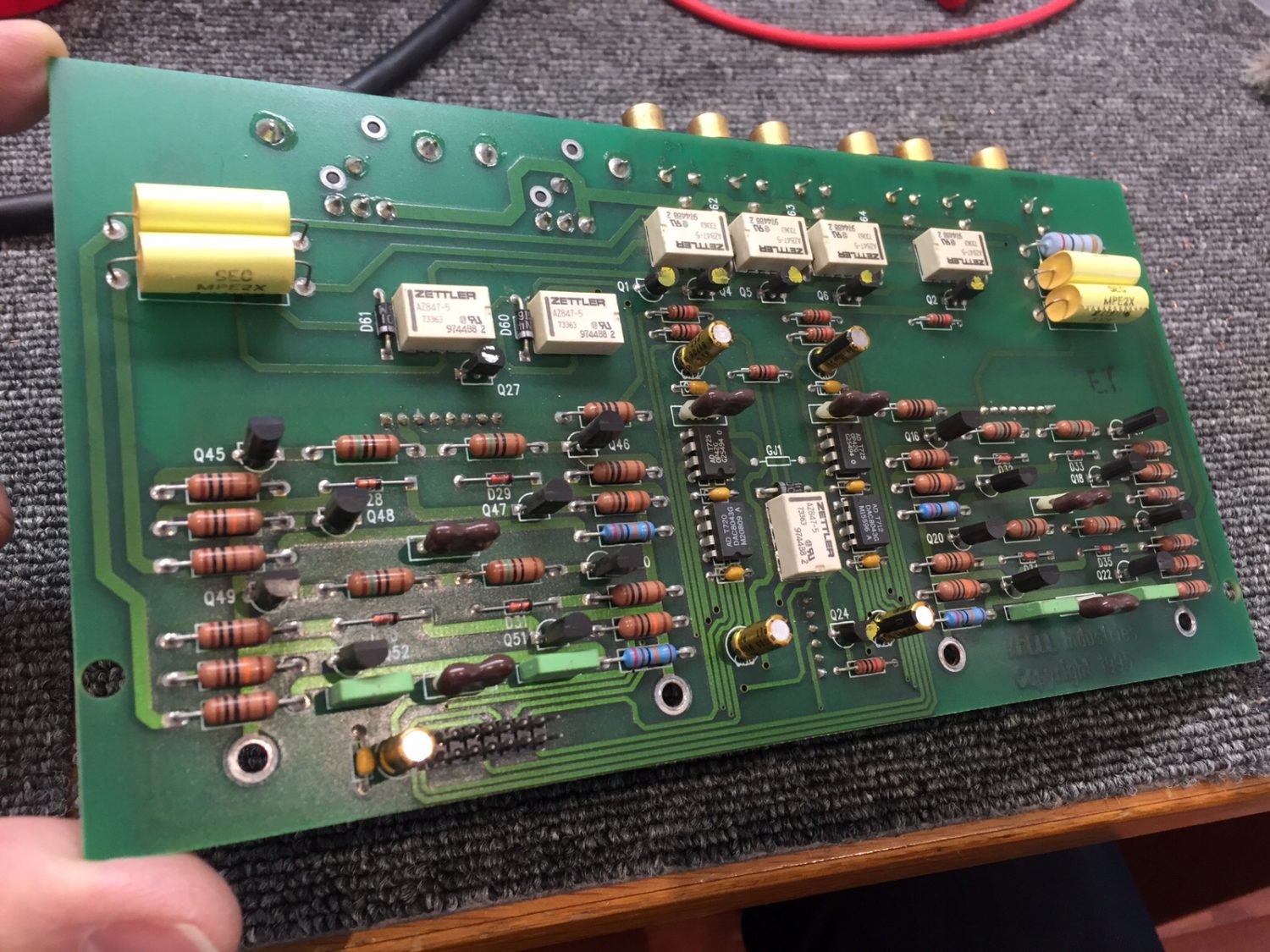
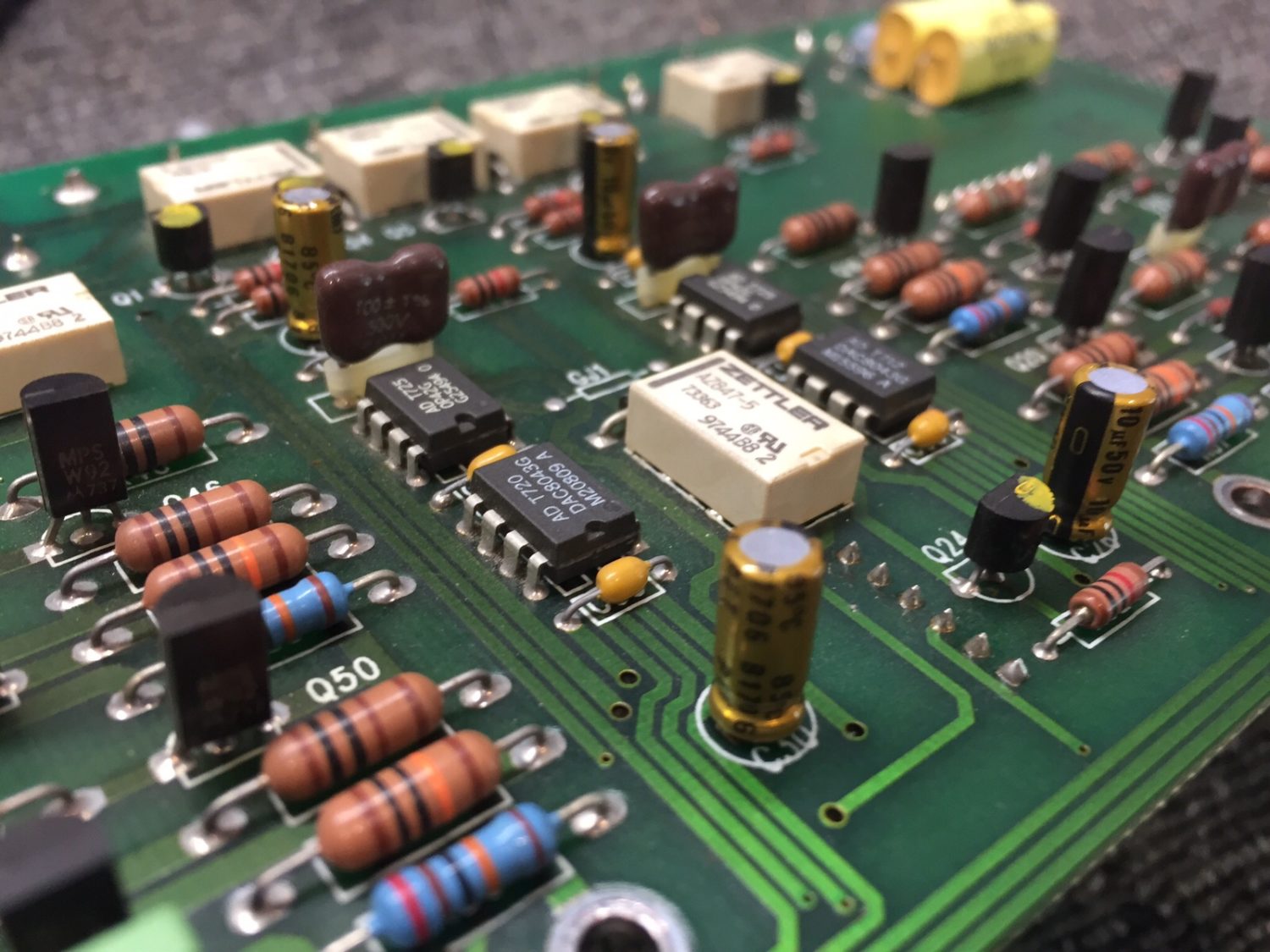
Preamplifier Board
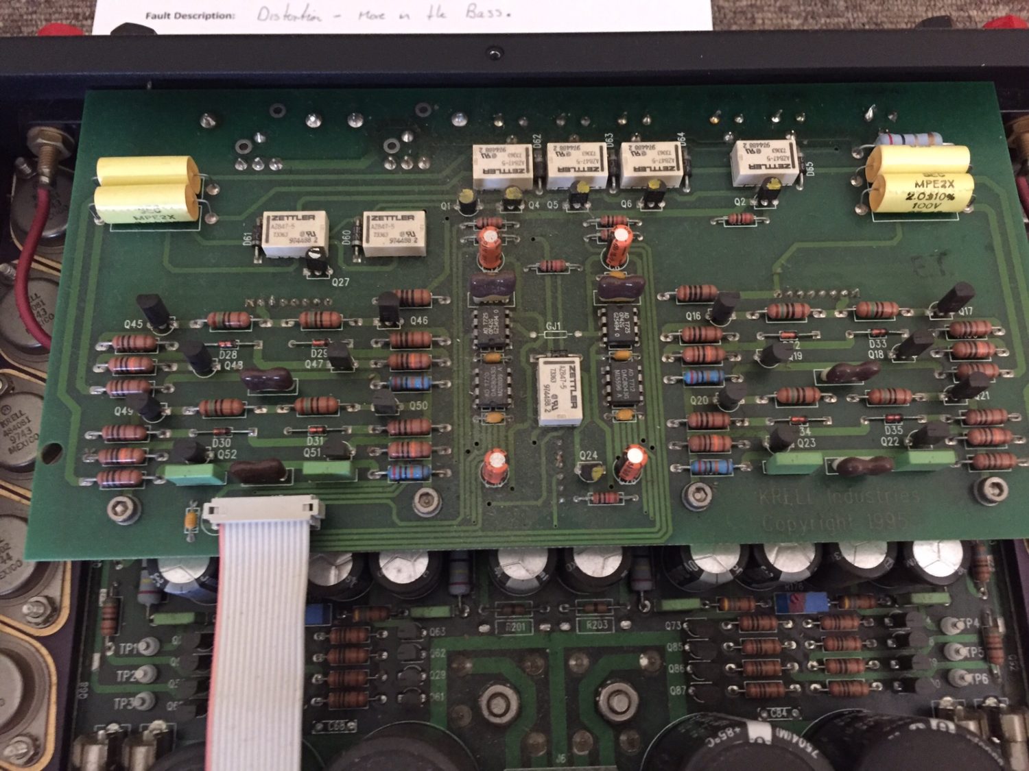
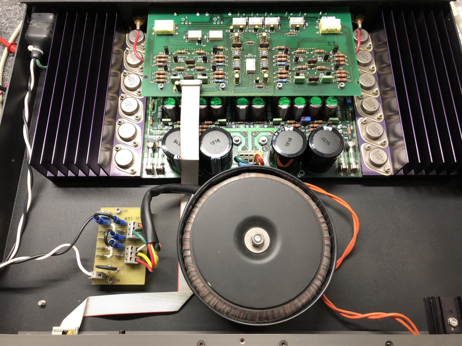
I tend to work through equipment in a logical sequence, so it makes sense to start with the preamplifier board in this amplifier.
Power Amplifier Board
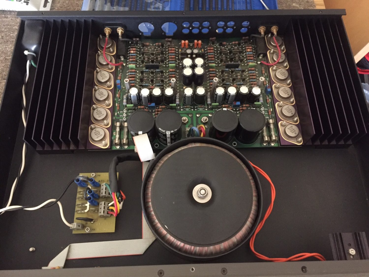
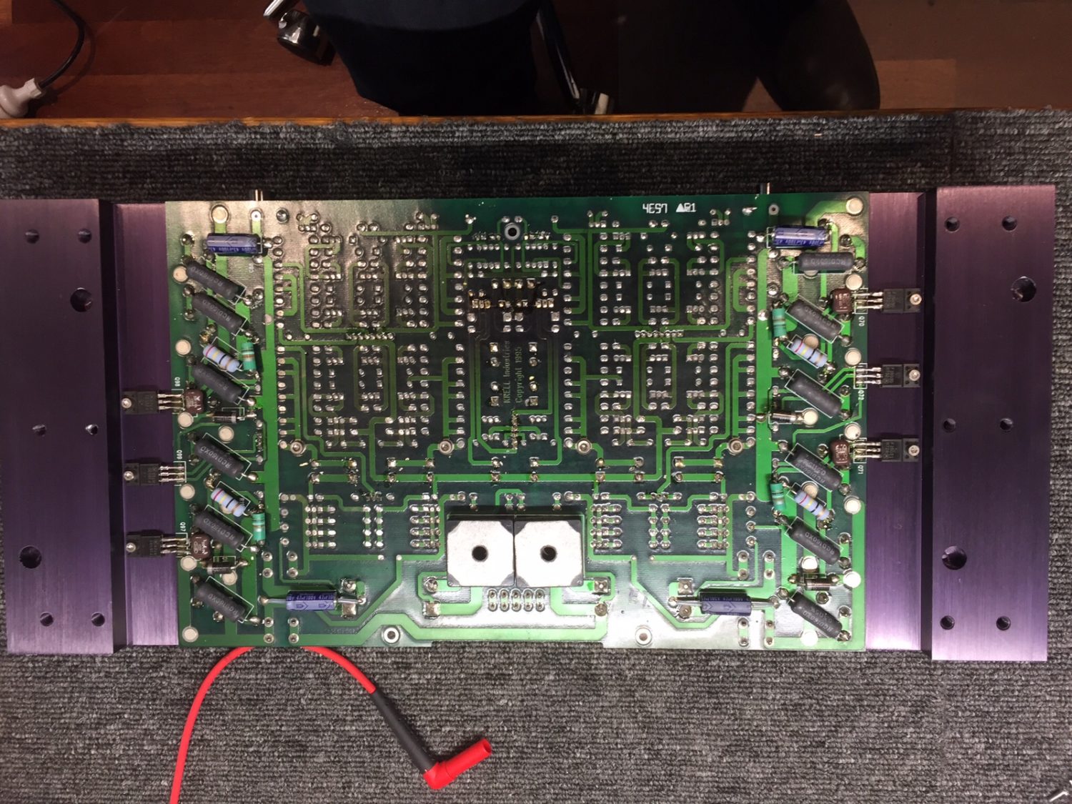
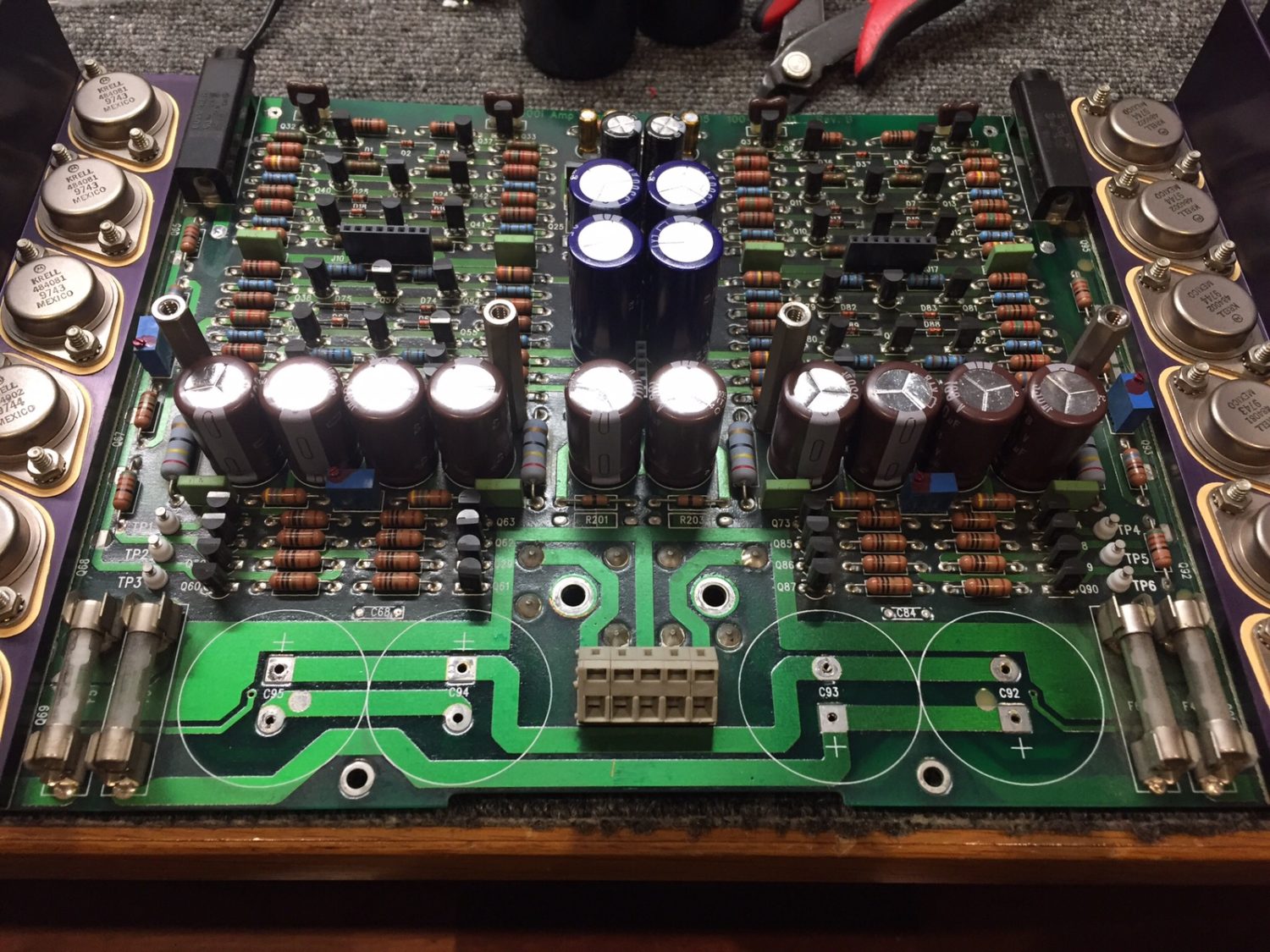
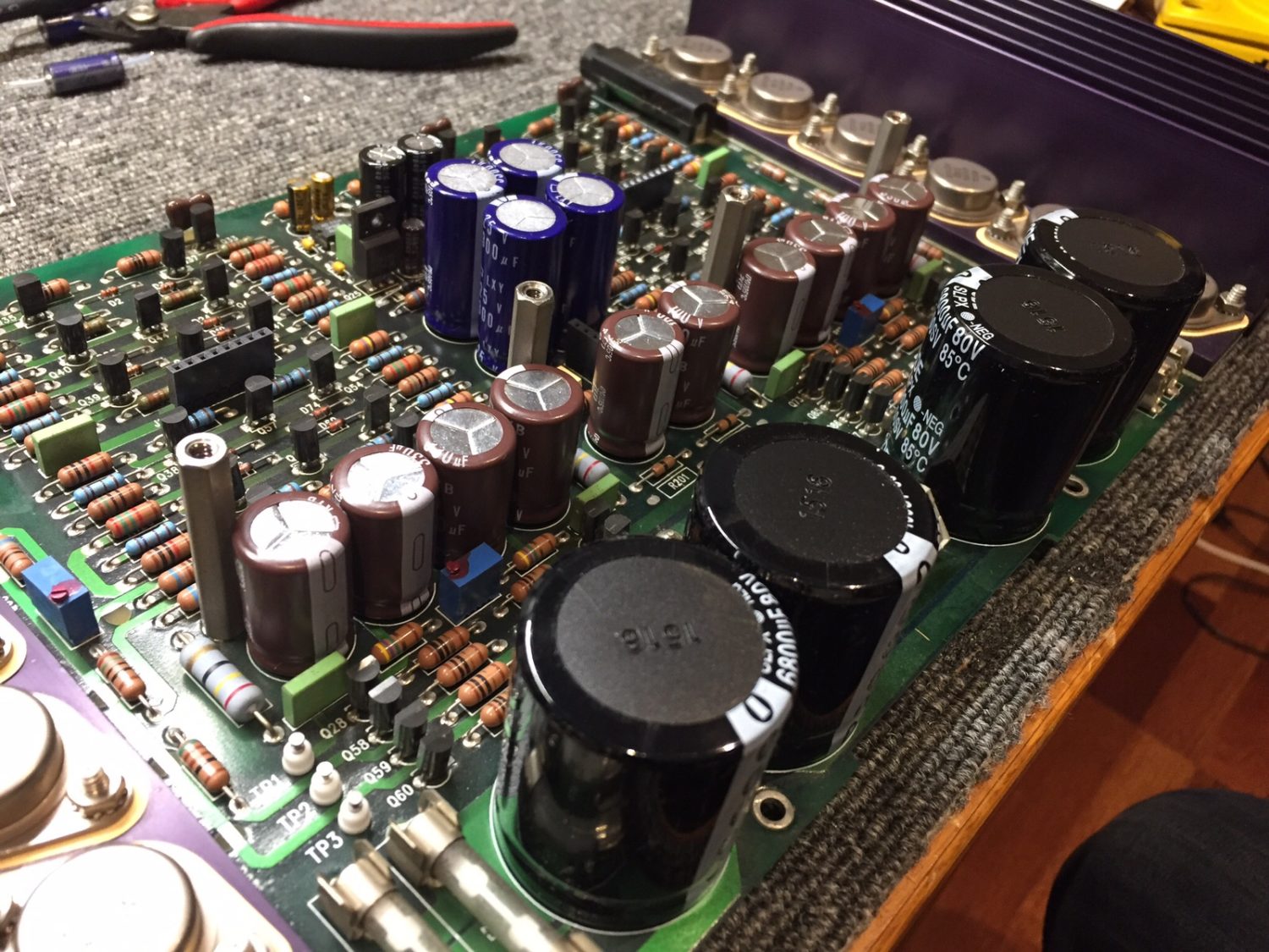
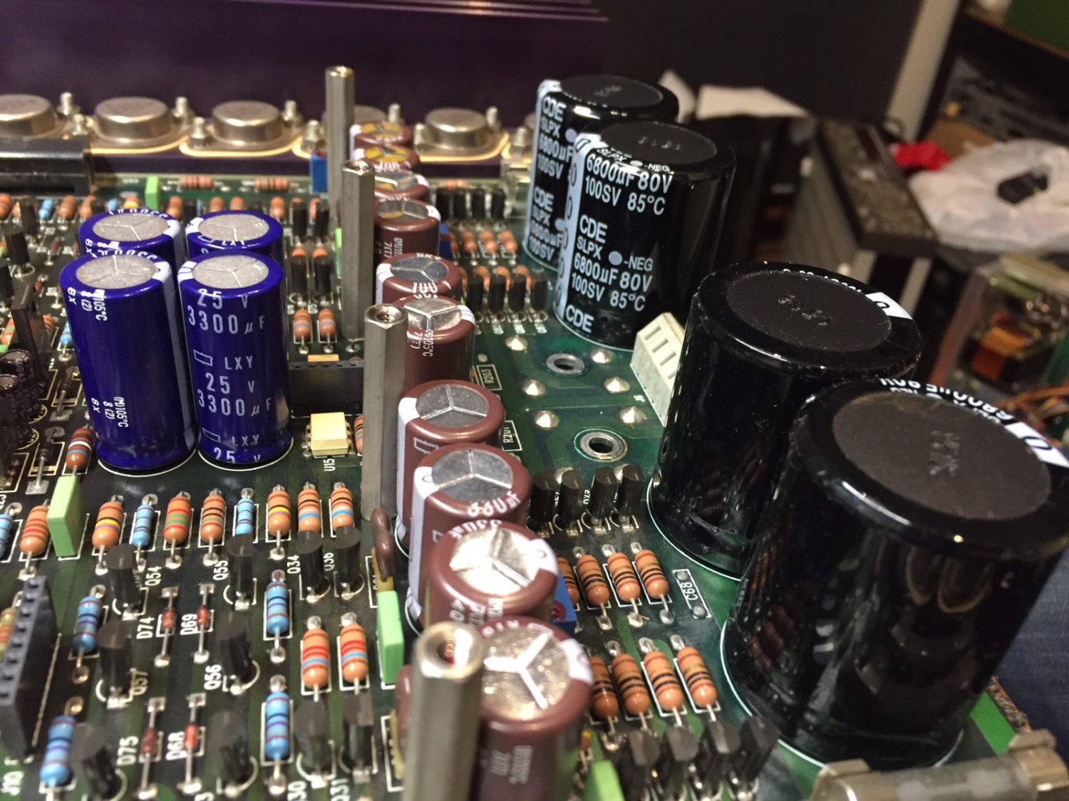
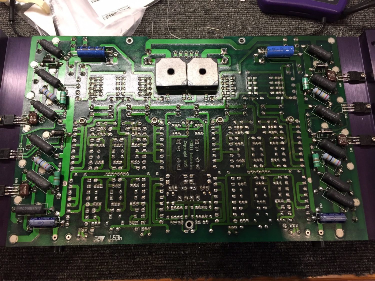
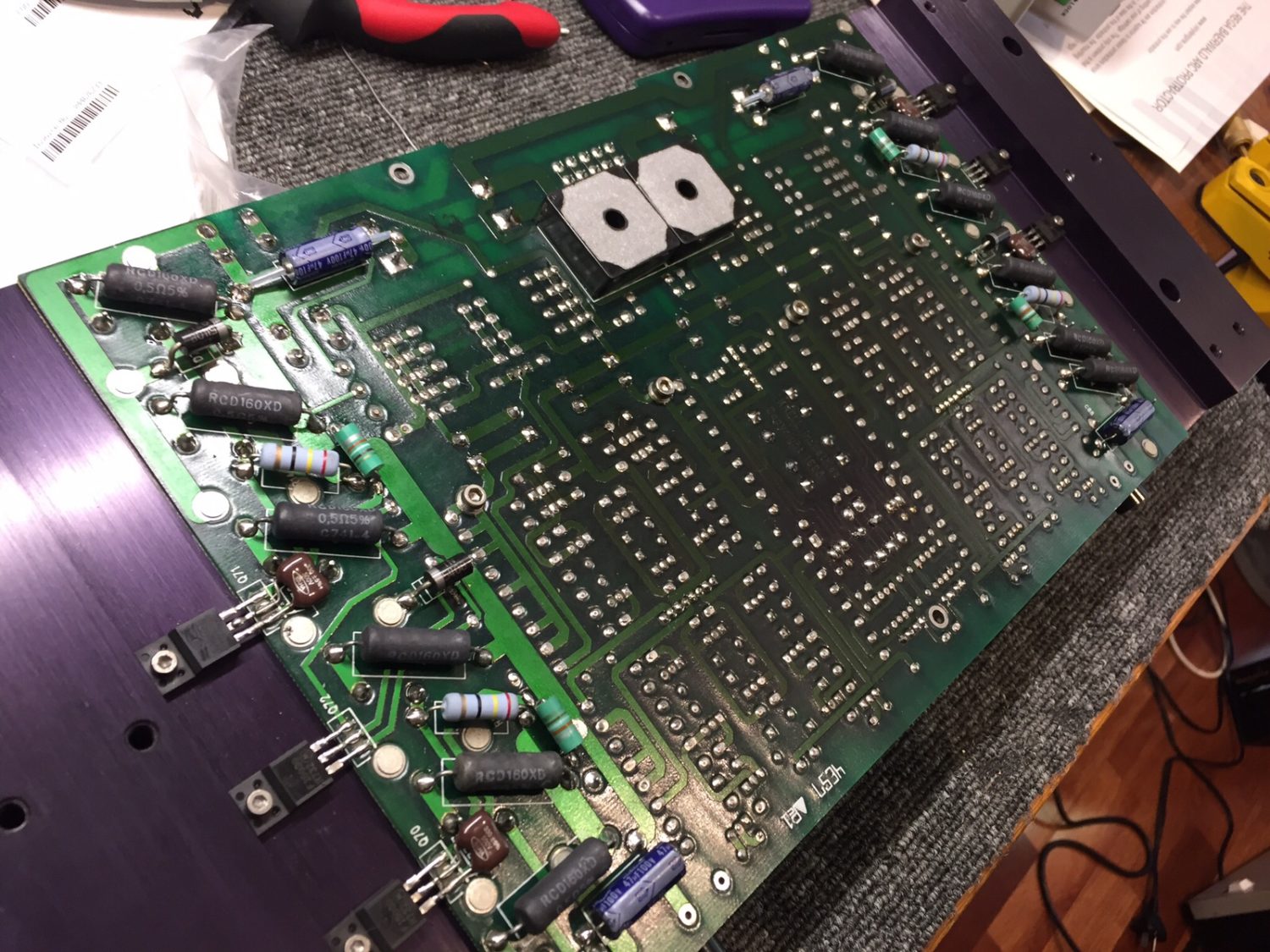
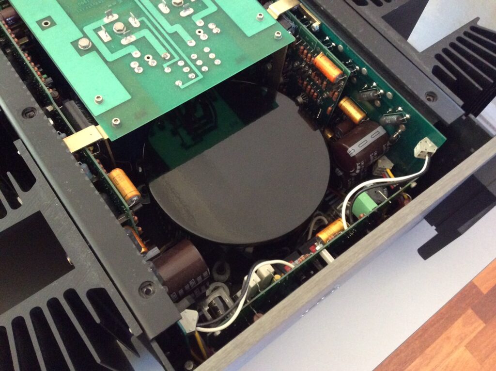
Now to get stuck into the board where all the heavy lifting is done. This amplifier and power supply board is a gorgeous one-piece fibreglass board. Typical of Krell is the absolute minimal use of wiring. The preamp board is connected to the main amp board by pins and pin headers. Power comes up through the board stand-offs, a really nice touch and highly reliable over the long term.
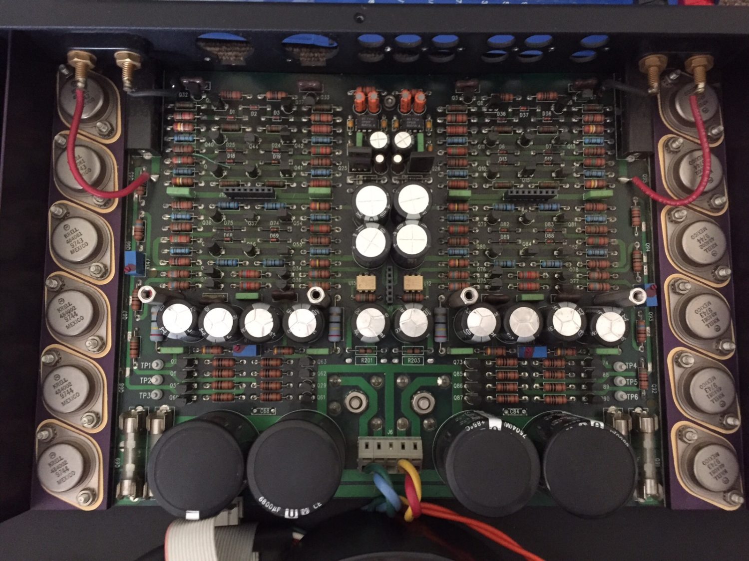
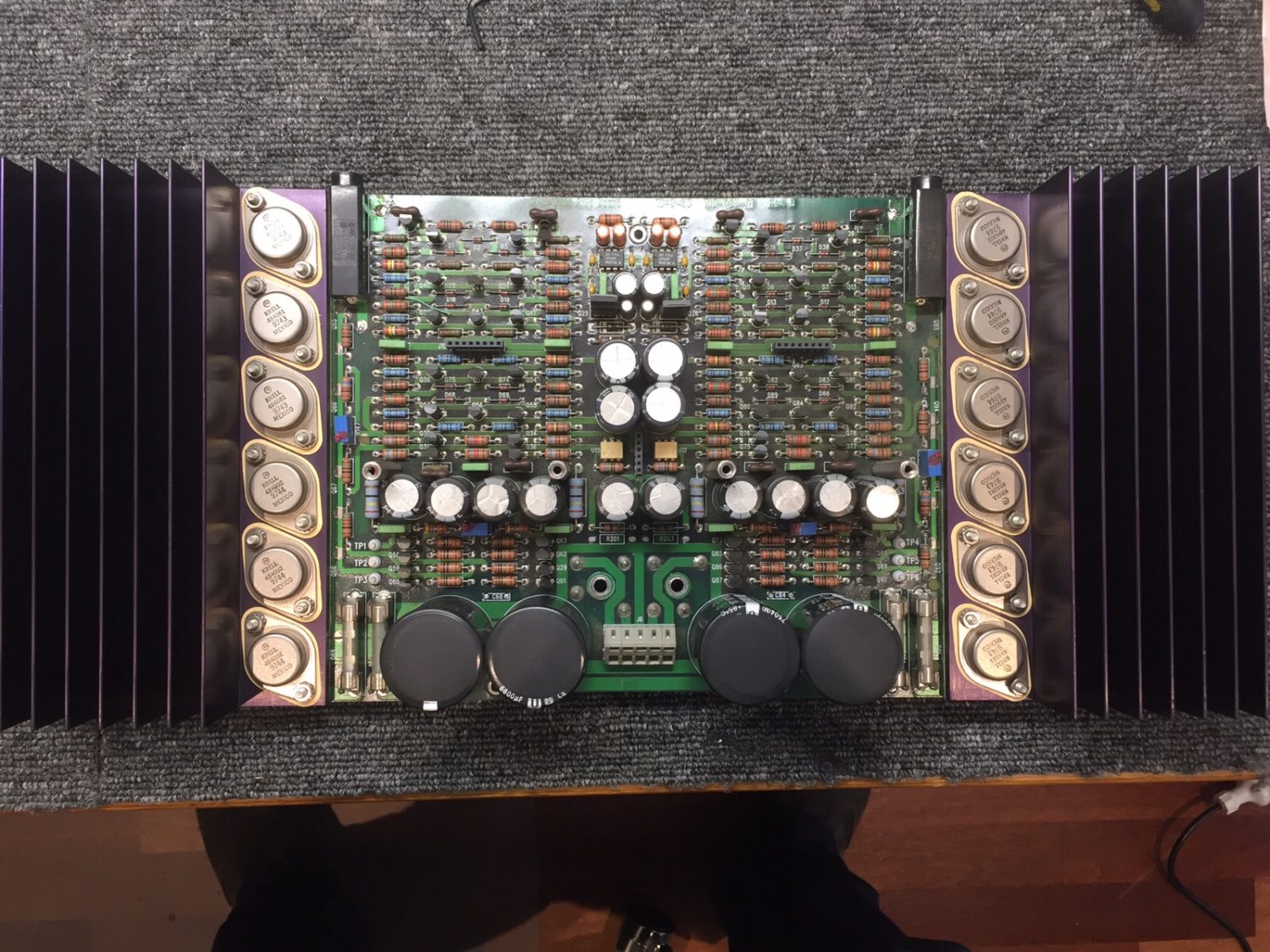
Power Supply etc
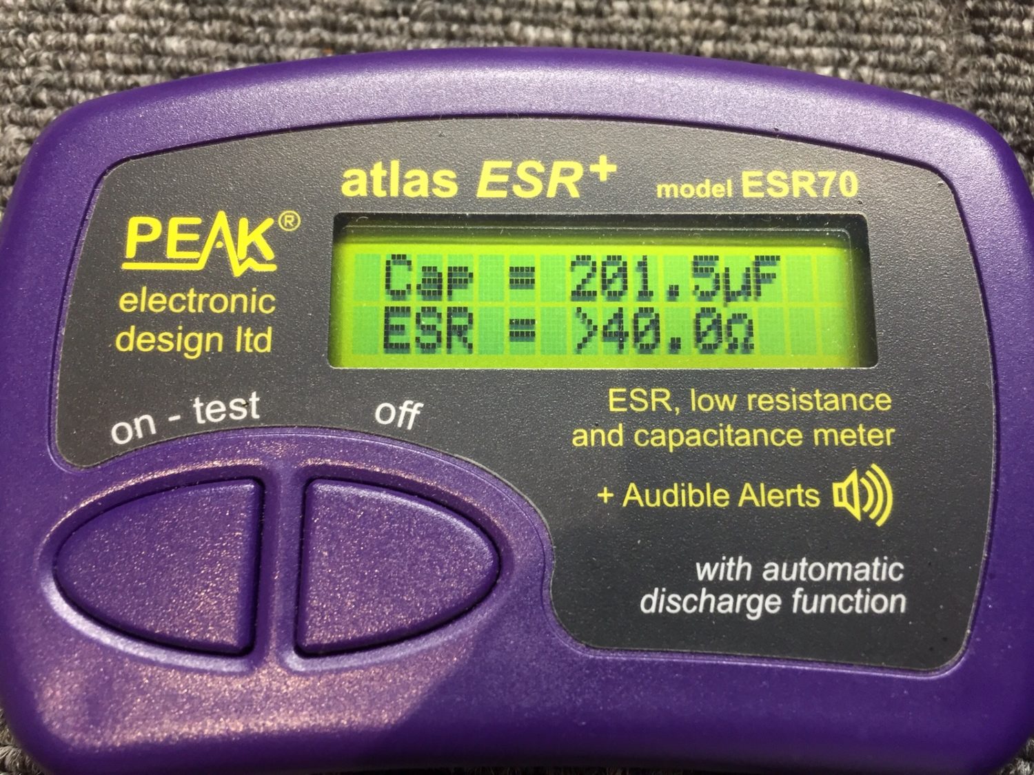
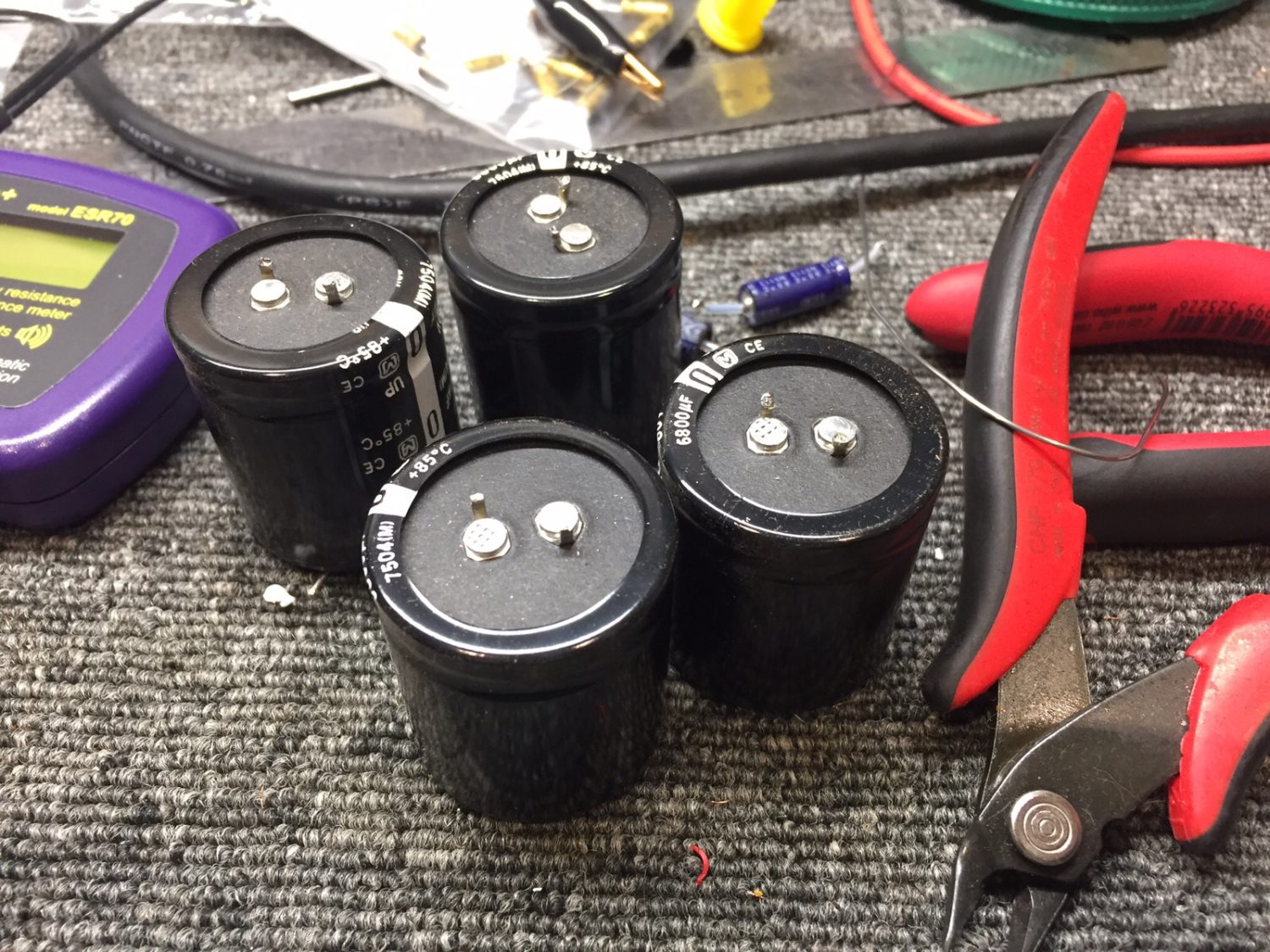
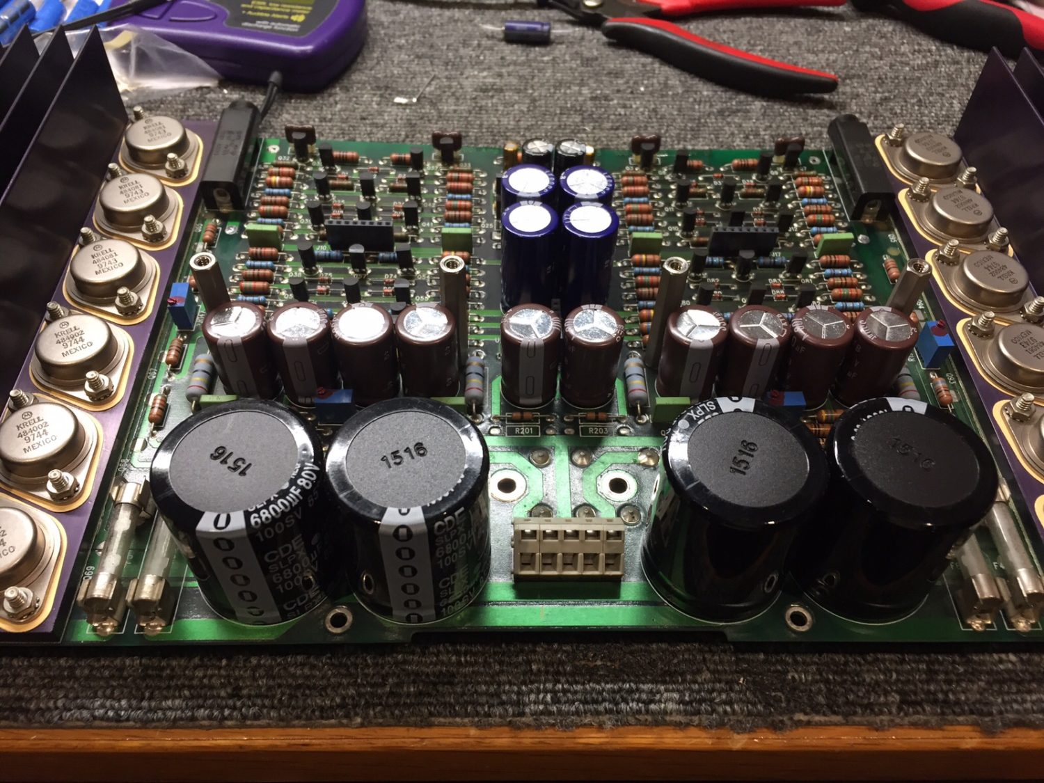
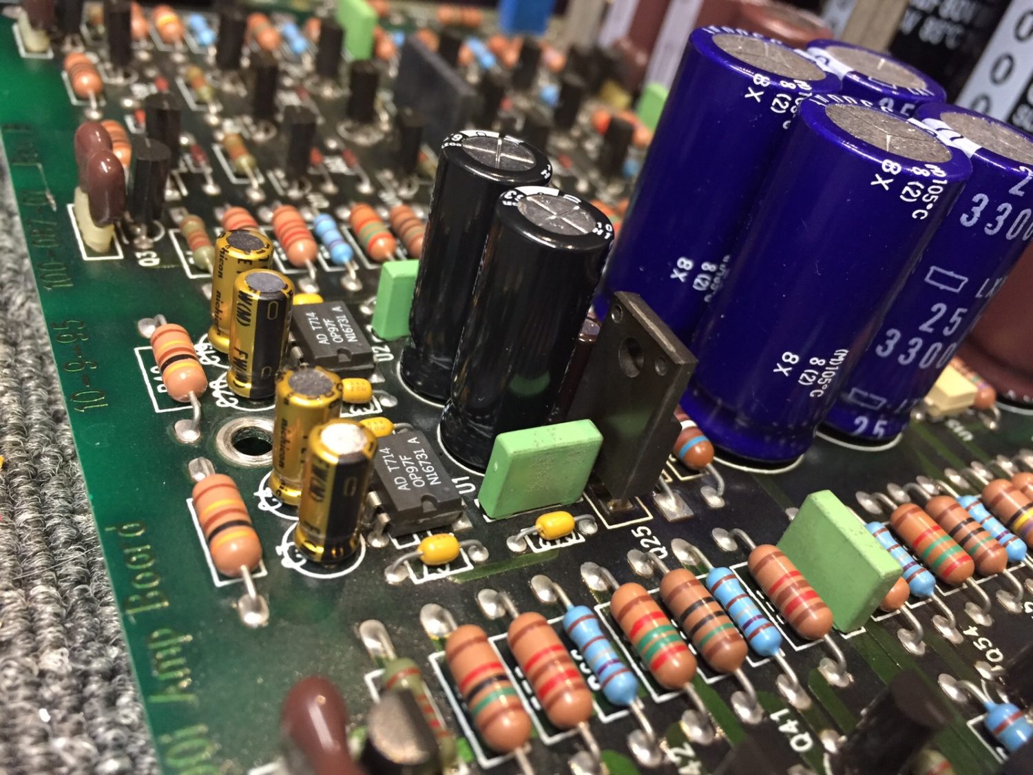
I replaced literally every electrolytic capacitor in this amplifier, simply because so many were bad. As mentioned, I used only lab-grade components from Nichicon, Panasonic, Nippon Chemicon, CDE, Kemet etc, to guarantee long service life for her owner.
Reassembly & De-Bugging
Time to put the KAV-300i back together. Thanks to Krell’s incredible tolerances, everything just fits perfectly.
After reassembly, I spent considerable time testing, adjusting and pulled her apart again, chasing a residual issue. To ease my curiosity, I tested every single semiconductor on both boards, because the amplifier was still occasionally showing signs of distortion, though dramatically less than previously.
I re-cleaned and prepped the board-to-board pins and did a little more re-working of joints and testing of resistors and transistors. Finally, she went back together again and tested perfectly, in fact, way better than spec.
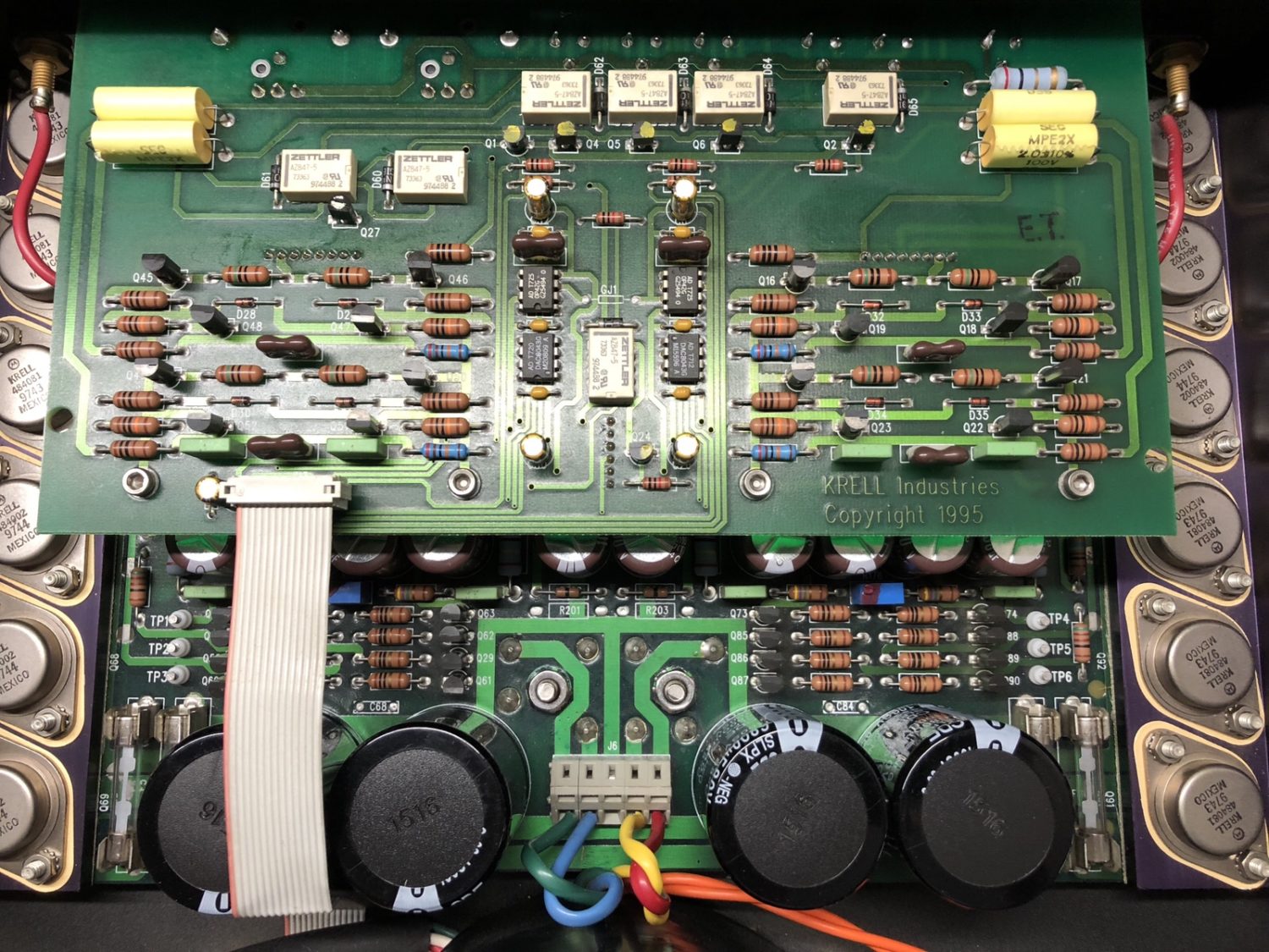
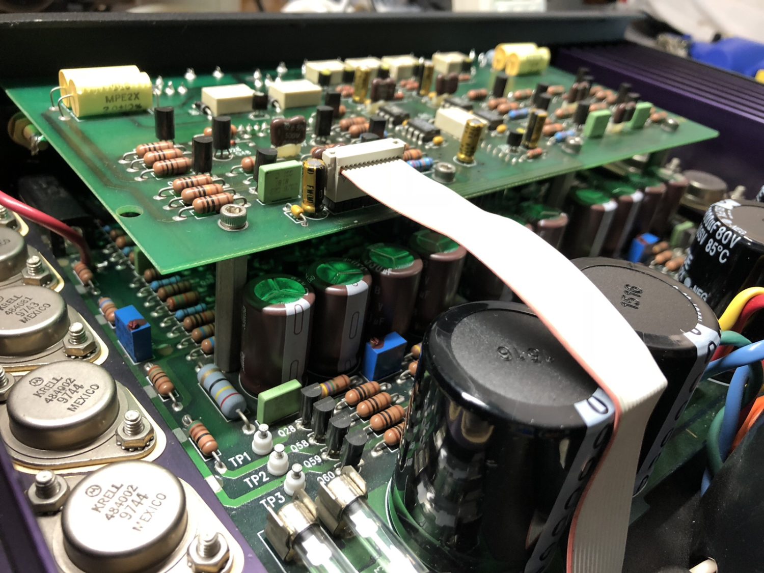
Testing & Measurement
A word or two about testing. I like to quantify things for myself and for my customers. To that end, over the years I’ve invested in the test and measurement instruments needed to characterise this stuff properly.
Here’s a good example, in the final testing and debugging of the KAV-300i. I feed in signals of known purity and amplitude and measure them again at the output of the amplifier. In a crude sense, this proves that signals pass all the way through the amplifier, but it tells us a lot more than that.
Measuring distortion of the signals output at the speaker terminals tells us a great deal about the health of the amplifier circuitry. In this case, it helped me to diagnose and fix this distortion problem. Having the right equipment takes the guesswork out of debugging and troubleshooting.
The extraordinarily low measured distortion of this KAV-300i is a testament to the design of this great amplifier and to the work I’ve done to restore her.
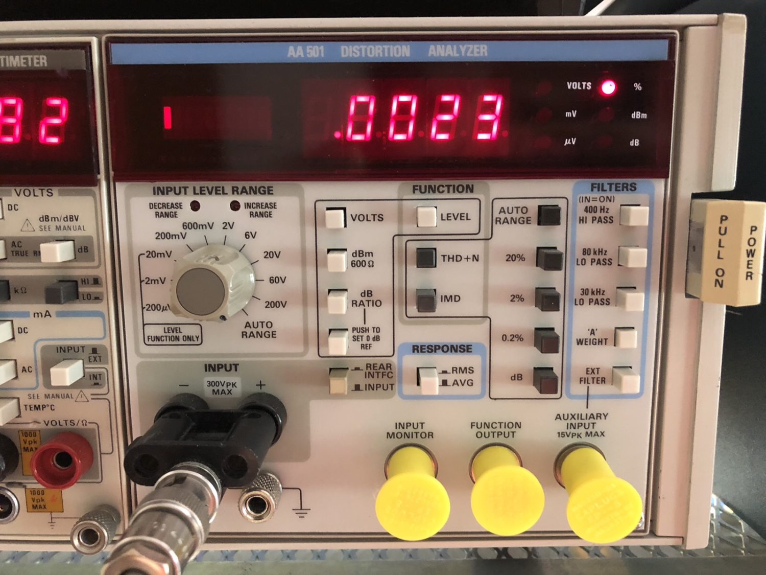
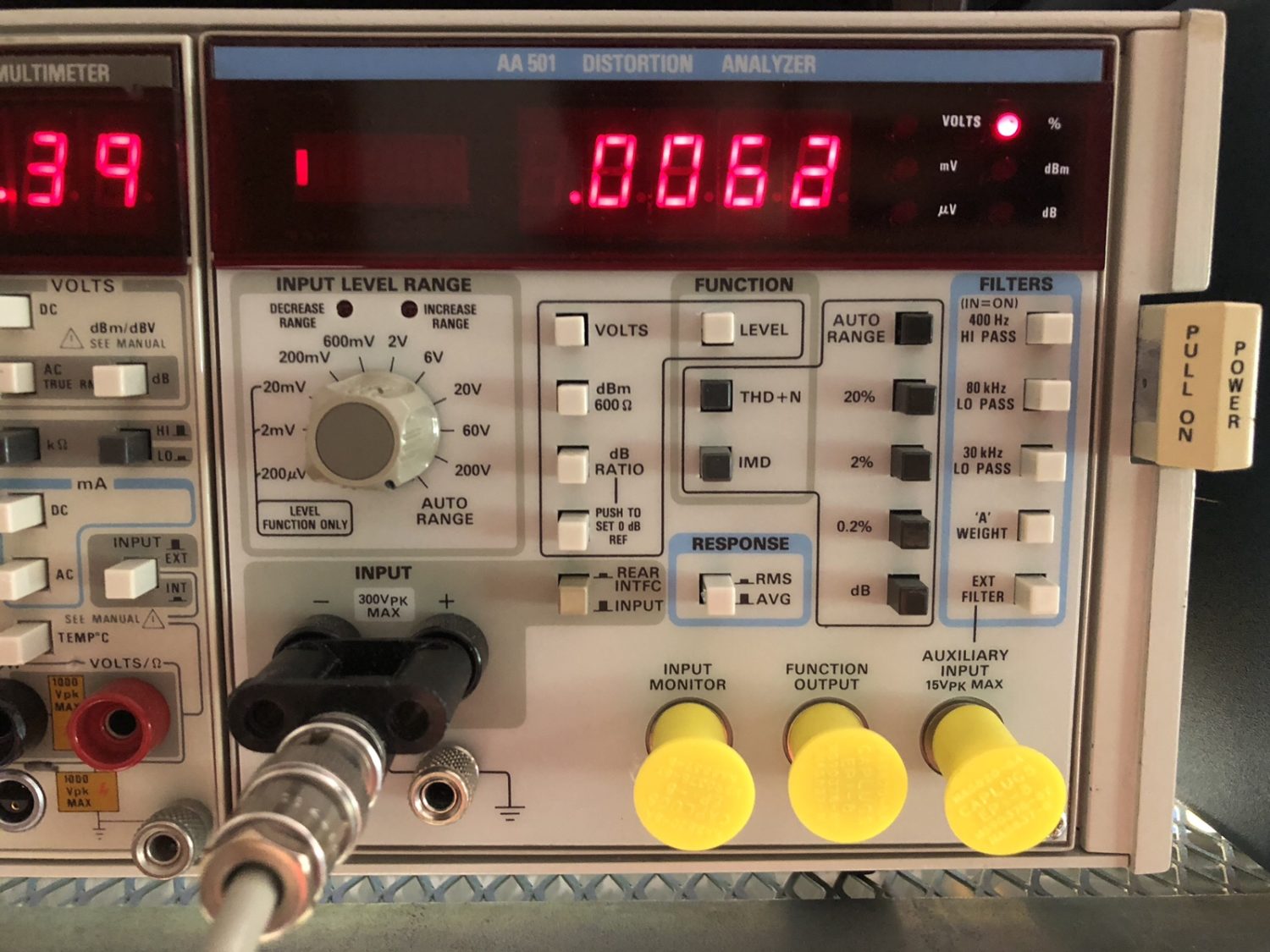
So that’s a look at the complete restoration of a Krell KAV-300i. I hope you’ve enjoyed this and found it informative. Don’t forget you can contact me (Mike), right here on my contact page, for assistance with your hi-fi gear.
Discover more from LiQUiD AUDiO
Subscribe to get the latest posts sent to your email.


Fascinating to read your work Michael
Always of interest to know about the vintage units and to see stage by stage pictures of what, what anf how you fix them
Keep posting
I am sure many others feel the same
Thanks Rodd, your feedback is always appreciated and really happy you liked the article!
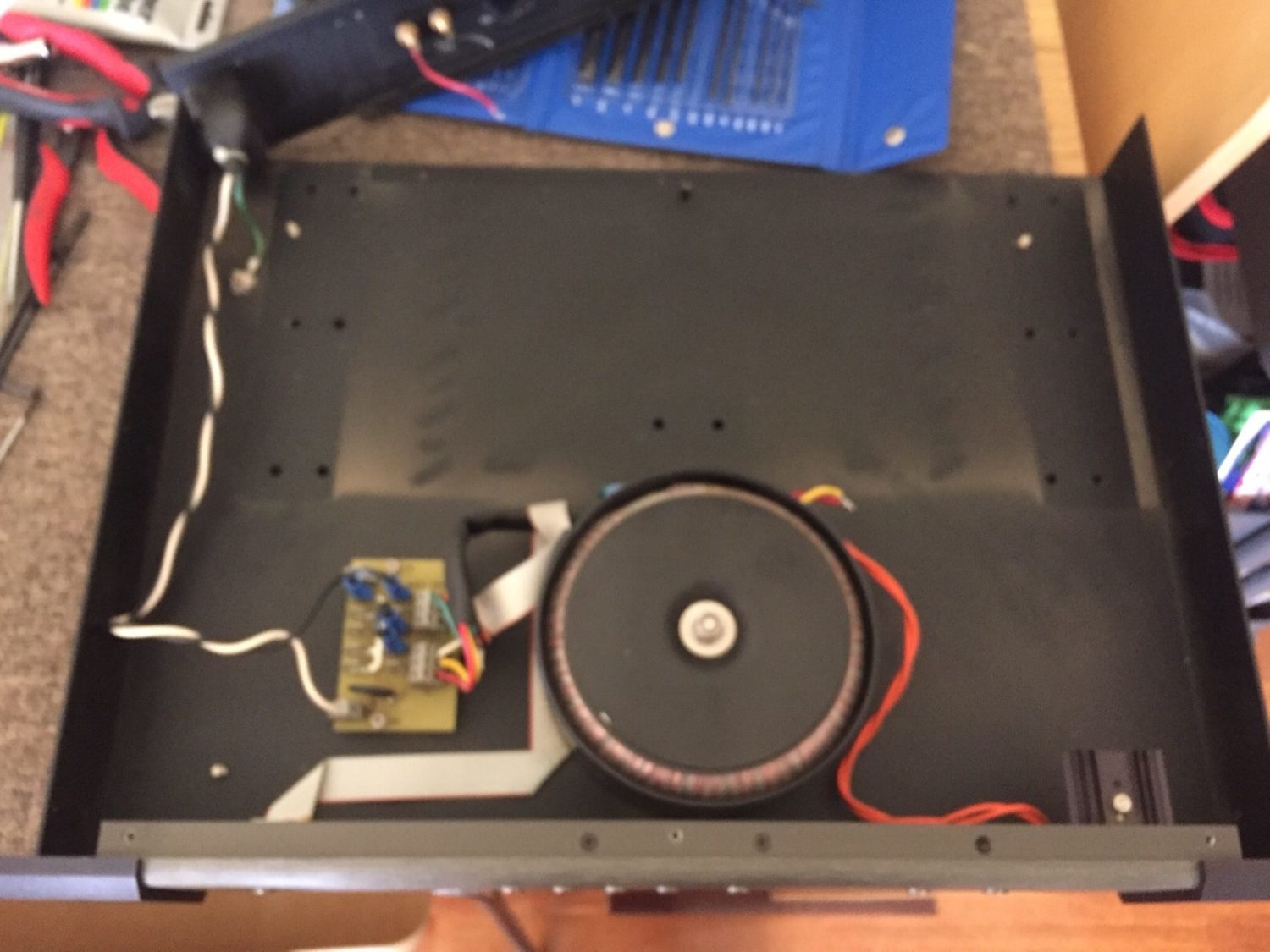
Most Excellent article. I am recapping my 20 y/o 300i following your guide. Hopefully will do a good job. The inside of my 300i is slightly different in the segment from the power cord to the toroidal transformer.
I have ordered the capacitors at Mouser Electronics today.
Andrea Torri
Northborough, MA
USA
Excellent news Andrea, very pleased you found the article helpful and best of luck with the restoration!
Mike. Nice article. Could you tell me what caps were sending DC current? Is it a specific set of caps? That is what my 300i is doing. Every time I plug it in I get a surge thru my speakers.
Hi Tim, thanks for your comment. I think you might be asking which caps were dead in this particular repair. Lots of caps measured low for C, high for ESR, and therefore were electrically leaky, meaning they passed some DC. I’ve repaired dozens of pieces since then, so I can’t remember exactly which caps were bad. More importantly though, it shouldn’t make any difference to repairing your amplifier. The only way to approach a repair like this is to test all the capacitors and then replace them, based on any patterns you find. You need the right equipment to test capacitors properly and of course the right soldering and desoldering tools. If in any doubt, take this to an expert. These are really nice amps and can be restored very effectively by the right technician. Good luck getting her sorted!
Excellent tips and very informative article.
However, I have KAV400xi, now almost 14 years, and the amp start to misbiheave in similar way as mentioned above. Audible distortion and shy bass on the medium-hither level.
On inspection, everything seems good, but the environment of this little monster run very hot, any component inside is hot as heatisniks. And 80% caps are SMD
Any experience with KAV400?
Hi Erden, glad you enjoyed this repair! Yes, I have experience with the KAV400xi, it will certainly need an extensive overhaul at this age and the SMD caps will form a big part of that overhaul. It’s tedious work, but it must be done. Leaking electrolyte will likely be an issue and must be dealt with as it is discovered. If you are local, you are welcome to call me to discuss the options.
I appreciate your comment and sharing your experience. Unfortunately, I’m not local but “down under” from your site (Europe), and this is only way to ask/comment 🙁
I received today most of replacement capacitors, still waiting for small ones. Due to very tight space the choice for appropriate PS electrolytes was limited, so I choose Vishay BC components 105C, since the originals are Nichicon LQ now obsolete 85C lytics, and wanted to go for 105C since the whole amp run very hot, thus 105C makes sense.
Two questions however arose for me during choice of small capacitors (incl. SMD ones):
1. the 22uF 6,3V in the power amp input and VAS (C1, C2, C64, C68…etc on the schematics) – all actually decoupling caps.
The question is – should they all to be replaced? And of what type? There is no clear marks what type they are ( lytic? Polymer?), and will be of very good advantage to replace them with 125C polymers (e.g aluminum or tantalum polymers)
2. same question is going to SMD (also mainly decoupling capas) in preamp section – 68uF/25V, which also run very hot. marking on the top of the caps says onla E4P, and values. There is stylish “O” also on top, which I do not know are they Oscons (organic caps) or maybe also polymers. On some forums, there a references that in the corresponding preamp KAV-280P, Krell puts everywhere (exept PS) polymer caps, but this can not be confirmed for sure.
3. Should be changed also the non polars? There are four of them, classic radial 85C Nichicons NP, and from the schematics I can see these are in the feedback loop. Here also planned to go with Panasonic non-polar (SU series), but I must go here with same 85C since there is no 105C bipolars.
Any clues and help highly appreciated.
Hi Erden, regrettably, I don’t have the time to provide detailed technical assistance of the sort you need here. I don’t have the schematic in front of me and I’m heavily time-limited by my workload. I receive many enquiries each day and they can become a black hole for me in terms of absorbing time, so I try to avoid long technical discussions, outside of those involving customer equipment. Be careful of forums for technical assistance, I suggest using replacement parts of the same type where possible, ie polar for polar, non-polar for non-polar, tantalum for tantalum etc. Triple-check everything and don’t obsess over capacitor types, just carefully repair her using parts at least as good as original and enjoy her again. Best of luck getting her sorted!
Hi Erden, did you ever found 125c of 22uf 6.3v in required size ? 4 yrs on and I am now doing my recap of the KAV-400xi and I can only find for other larger ones using hybrid polymer ones for 125c. Cheers,
Well, I found only polymer type, and that’s good!
Someone from krell service answered to my request that “they have not in (their) record for failimg any of those particular type of capcitors…” -and usually they did not replace them at all.
But, in case of need, the can be replaced with rhe same and/os sloghtly bigger voltage (s.g 10V kr 16V).
Giving this- I just left the originals, replaced the main PS 6800uF and several decoupling.
The amp works since then as new
Those 68uf 25v ones marked “o” are Nichicon’s logo sometime used and I believe all smd are also Nichicon like UUD clearly marked for 47uF 25V ones as are the thru holes ones, VK, VR and SME(BP) while I still cannot figure out the input coupling NP dark blue ones in the preamp pbca that are marked strangely Пc like some russian capacitors.Cheers,
For the power pcba of stock Nichicon SME BP 85c ones, I replaced them with Nichicon EP BP 105c ones but I want to maintain/not risk some SQ and used the Nichicon ES BP 85c ones in the preamp pcba for input coupling to replace the unknown stock Пc NP ones … figured that I can easily change them out if needed since preamp pcba is more accessible. Cheers,
Sure, my appologies.
Keep excellent work, and looking forward of more examples of good refreshments here
Hi Erden, no problem at all and no need to apologise, thanks for your comments and I’m glad you are enjoying the site, much more coming. Let me know how the overhaul goes!
Hi! Thank you for this great article.
Can you tell me(if you remember this), how much does the case of this amplifier heat up when it is on and sounds at a low volume? And does it warm up in standby mode?
I purchased this unit and was faced with the fact that its body heats up to 40-45 degrees, even in standby mode. And when it is turned on and works at a low volume, the case heats up to 50-60 degrees. And I mean exactly the heating of the case, meaning that the transistors inside the amplifier should be heated even more.
Thanks!
Hi, my pleasure. This definitely doesn’t sound right. My experience with these is that they need extensive maintenance at this age and many times people have fiddled with them. This one sounds like it has a fault, idle Pd is low enough when correctly adjusted that the sorts of temperatures you mention are not possible. Note my emphasis on correctly adjusted!
Thank you. Mike! I understand correctly that by correctly adjusted you mean the bias adjusting? Or something else?
And please explain (without abbreviations) what “idle Pd” means? English is not my first language, so I’m not sure if I understood correctly.
Many thanks!
My pleasure! There are bias (quiescent current) and DC symmetry adjustments, all of which must be made correctly. Idle Pd refers to power dissipation at idle. If you have more questions of a technical nature, you can get in touch via my Contact page.
Mike I am just about done recapping the same as you have here. I need 1 rca jack as the ground caps pulled off. Kind of unusual design. Ground in the middle and back in the 3 pin footprint. Both insulators are black. I have a box full of panel mount dual rca but not this one.
Thank you
Hi Rick, I’d try the usual commercial vendors for this, they are out there.
Liked your restoration of the Krell .Got a 300i myself and I am very impressed with it. Brought one for a $ 1000 [it was a trade] and it performs perfectly .Best buy I had in a long time Regards Steve
Great work there Steve and thanks for stopping by!