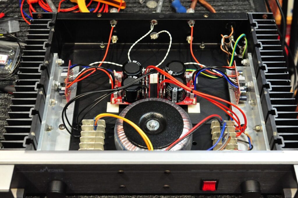
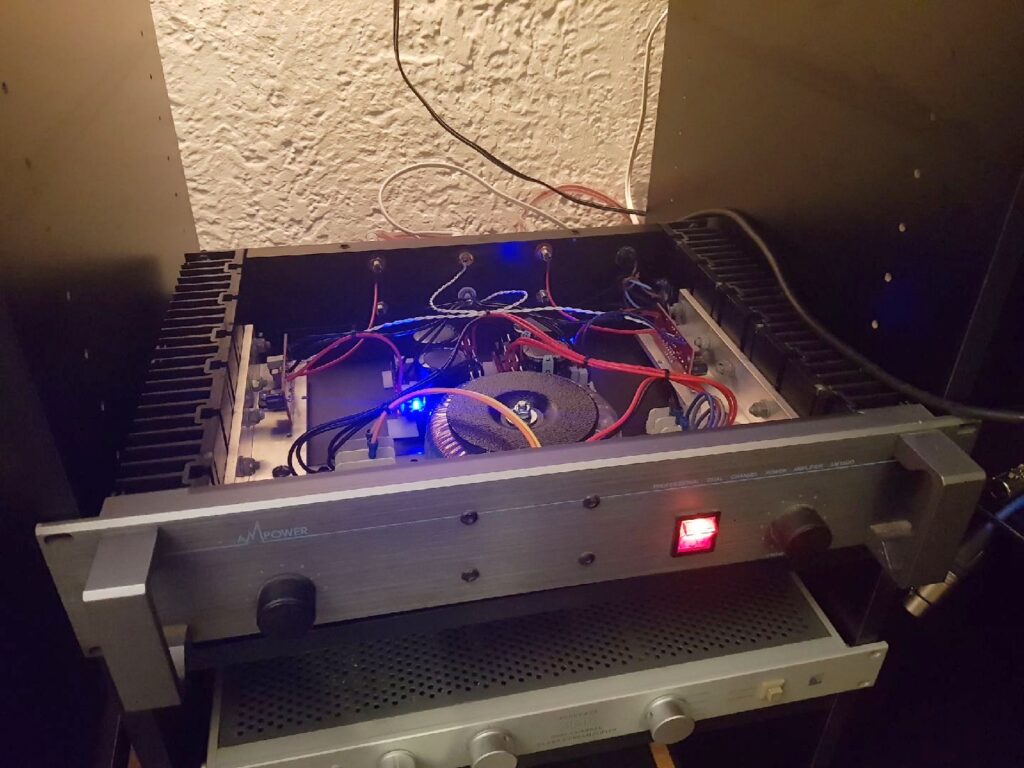
After successfully building my LM3886-based gainclone project amplifier, I’ve decided to build a version better suited to driving low-impedance loads.
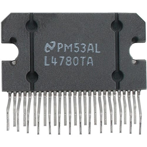
This leads me to the LM4780 chip from TI, which is just two LM3886 dies in one package. It can be used as a stereo amp, or a bridged or paralleled mono amplifier. The datasheet is the best place to start when designing an amp or implementing a chip like this.

Things to look for include the safe operating area graphs, which help determine power supply rails and maximum power dissipation into various loads. The bridged configuration gives double the voltage swing into 8 ohms, but essentially the same performance into 4 ohms. I want the amp optimised for driving 4 ohms and that means connecting both amplifiers in parallel.
Design Features
In this amp, I want to optimize certain design aspects to capitalise on the advantages of the LM4780. Design goals for the LM4780 gainclone project amplifier are as follows:
- Optimised for driving 4-ohm loads – each LM4780 will be configured for PA100 operation as per the TI application notes
- Very low power supply impedance
- Therefore dual mono, including separate mains transformers
- Shortest wiring possible
- Localised power supply C, wherever possible
- Minimum number of parts to obtain desired characteristics
- Therefore no active regulation
- No input network
- No output network
- Careful matching of load-sharing R
- Minimal feedback
- One box design
I am going to use Peter Daniel’s well-regarded LM4780 dual-mono kit as the basis for my design and make whatever adjustments and modifications I choose to along the way. Unfortunately, Peter seems to have shut his site down, and my link to it no longer works.
Other Considerations
I plan to use an unregulated power supply. My thinking is that the LM3886 and LM4780, by design, have extremely good rejection of PSU ripple and noise. It’s so good in fact that many people choose to use just 1500uF of C per rail, right at the chip with no other ripple filtering. From the spec sheet, the rejection is 100 – 120dB per rail and 110dB common mode rejection which is amazing.
I’m going one better and keeping the 1500uF of C per rail at the chips, but backing that up with 22000uF per rail further back. I will bypass these with 0.1uF film caps. Having large caps close to the chip should provide extremely low power supply source impedance. The large main reservoir will provide energy storage for good transient ability, helping to maximise impulse performance and the amplifier’s ability to drive low-impedance loads.
I see no point in regulating the power supplies, as any noise and ripple will be rejected by the chip and there won’t be much anyway. I didn’t want to raise power supply Z by introducing regulators and the transformers won’t be loaded up significantly, so the rail voltages should never sag much.
I will pay close attention to ground and signal returns as I’ve done with the first amp. I’m also not going to cannibalise the first amp as I thought I might – that way I keep it as a fully functioning unit and can do comparisons etc. I was going to re-use the PSU boards and filters, but that just leaves me with a bunch of non-functioning crap! This way I will have two complete amps.
Watch this space as I will be updating my progress here…
Update: Umm, sorry guys, no further updates as I never did end up building this but I sold the project to someone else who did!
Discover more from LiQUiD AUDiO
Subscribe to get the latest posts sent to your email.


Did you end up building this amp? I am interested in doing exactly what you describe.
Not yet Ricky, too many repairs and not enough time, but I will get to it eventually! Good luck with yours!
I’m guessing you never built this Mike?
I just bought a completed one! 🙂
Hi Jon, I built and still own the 3886 project but never got around to making the 4780 one and sold the kit a year or two ago. I hope you enjoy yours!