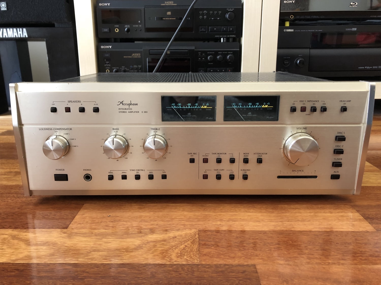
For those who haven’t heard an Accuphase E-303, they are one of the sweetest-sounding integrated amplifiers. Come with me as I repair and overhaul this one.
Given everyone’s sitting at home dealing with the Coronavirus, I decided to finish this Accuphase E-303 article, for your reading pleasure. I started writing this one 18 months ago, that’s how many articles I have in the pipeline. I’ve clearly got a bit of catching up to do.
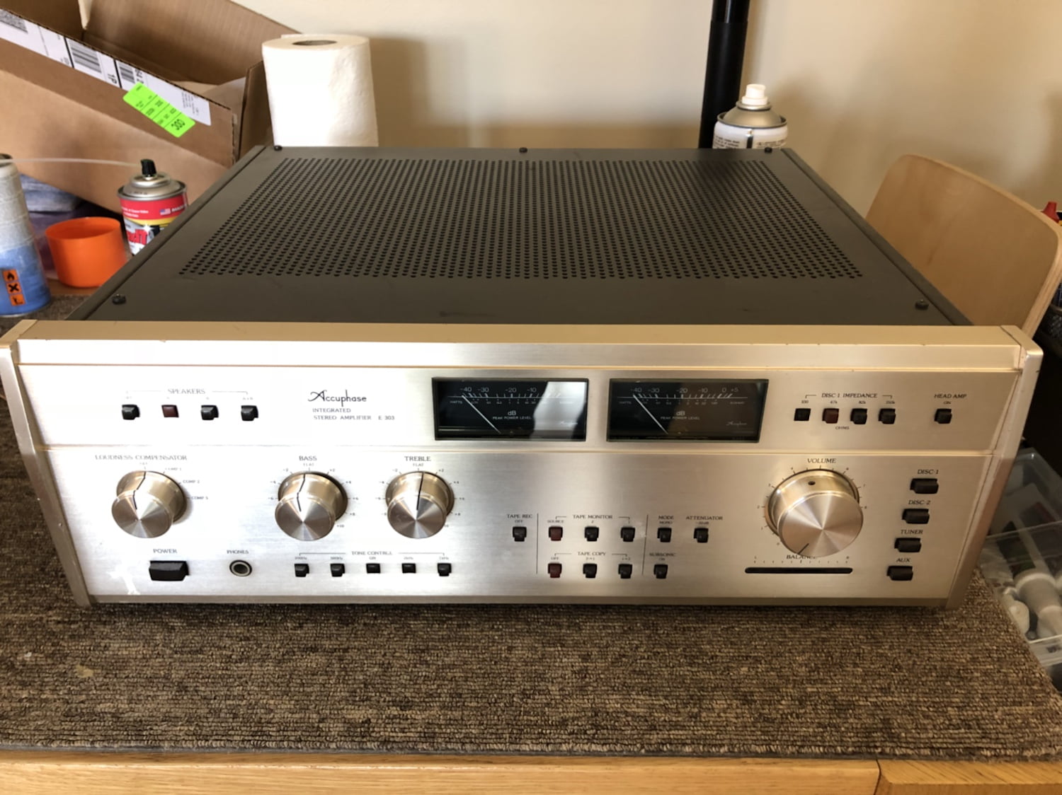
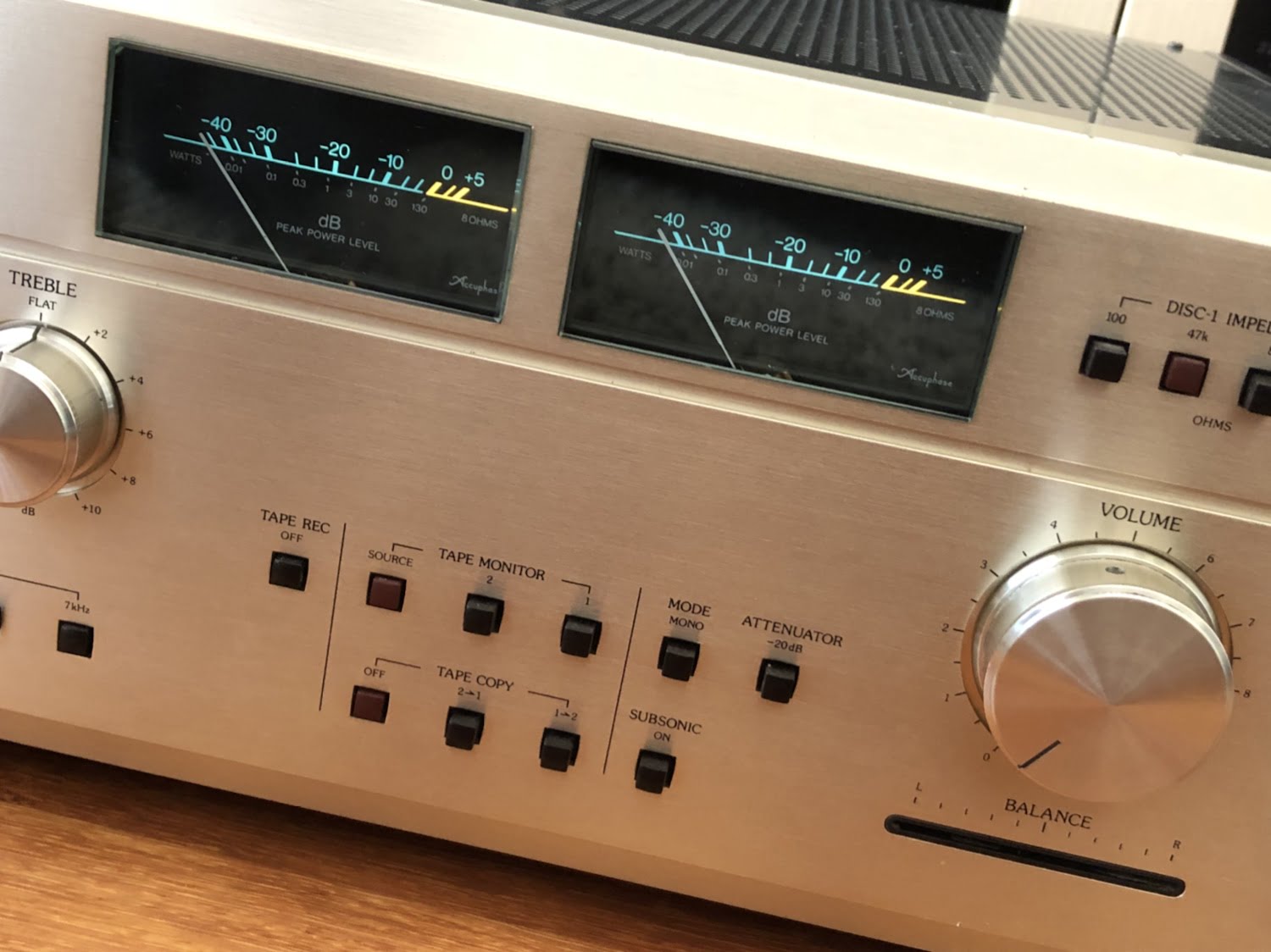
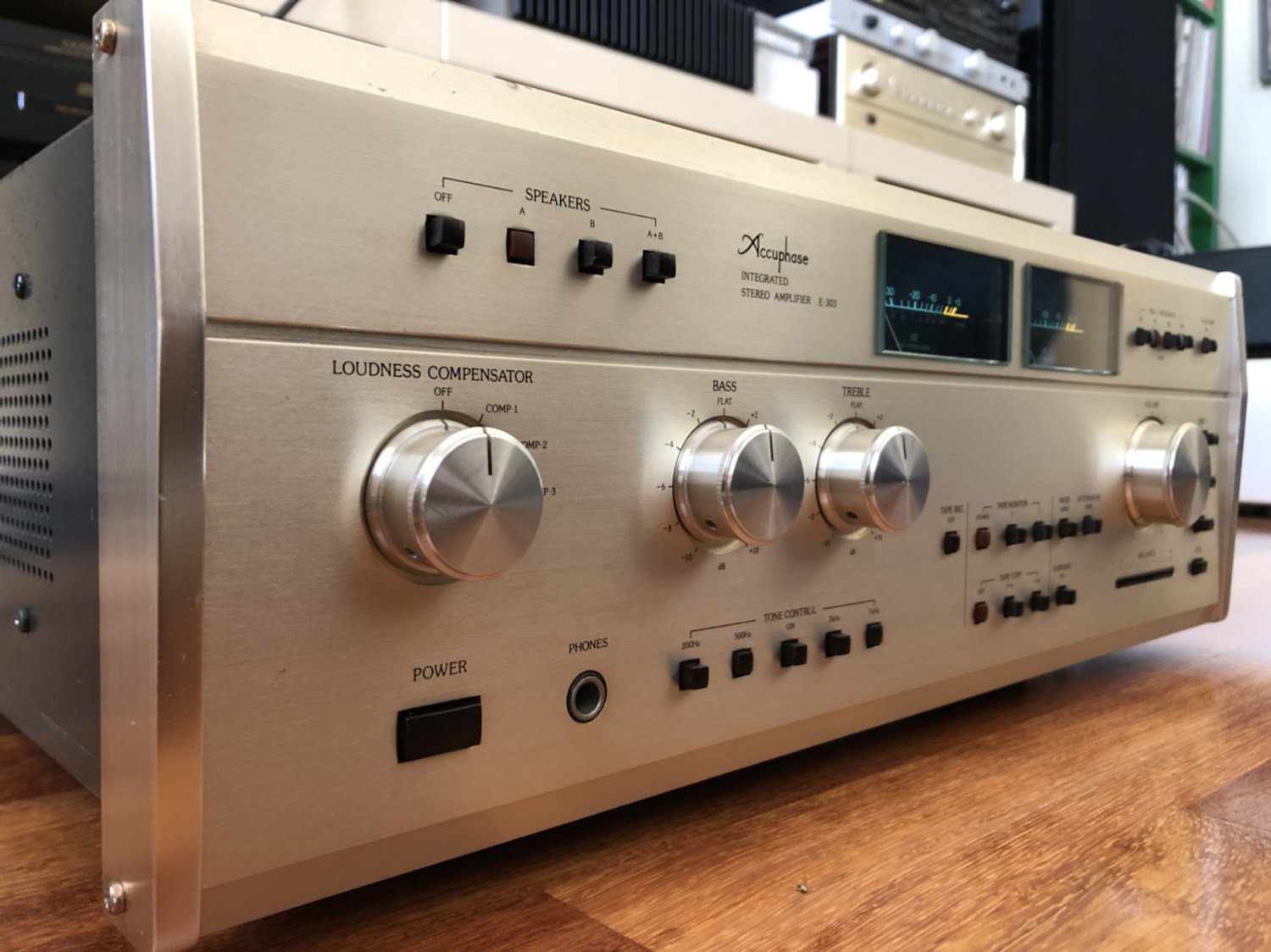
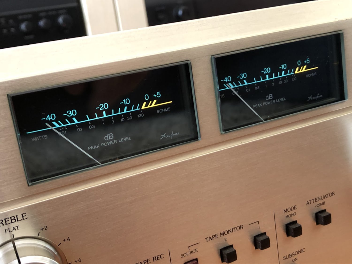
The Accuphase E-303 is a heavy, full-featured integrated amplifier with MOSFET output devices, superb sound and robust construction. I listen to every piece of equipment I work on and, out of hundreds of integrated amps I’ve heard, a well-sorted E-303 like this is one of the sweetest sounding integrated amps you’ll find.
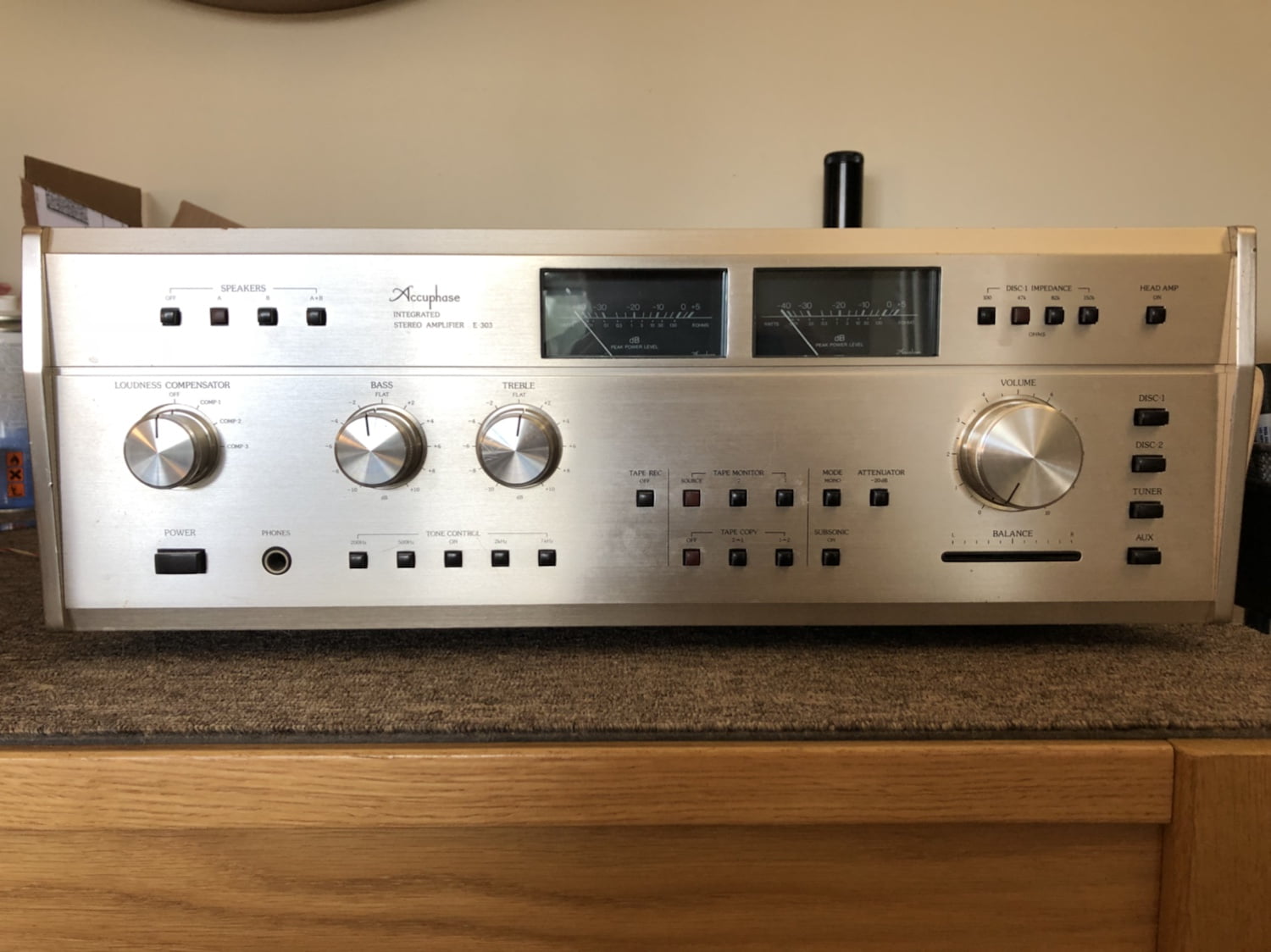
Accuphase released the E-303 integrated amplifier way back in 1978. Back then it cost 245,000 Japanese Yen, roughly equal to $3750 AUD or the price of a new small car, 40 years ago. You can imagine the equivalent cost now, allowing for inflation. I calculated it an eye-watering roughly $20K AUD…
Whatever the price, Accuphase really hit it out of the park with this model and the E-303 and E-303X remain incredibly popular. They change hands for around $1500 – $2000AUD and at these prices, compared to new gear, they are an absolute bargain.
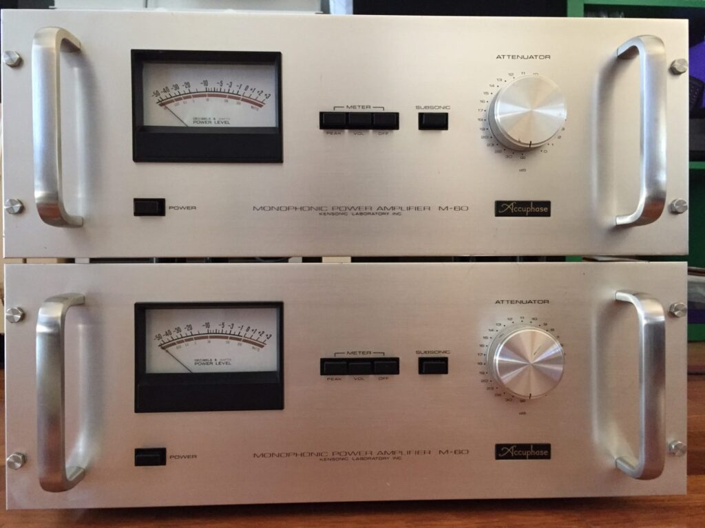
By the way, if you like Accuphase articles and equipment, make sure you read about my Accuphase E-202 and Accuphase M-60 restorations. I also have Accuphase E-206, E-301, P-20, P-300, T-105, T-100, DC-330, C-200L, C-230 stories in the pipeline.
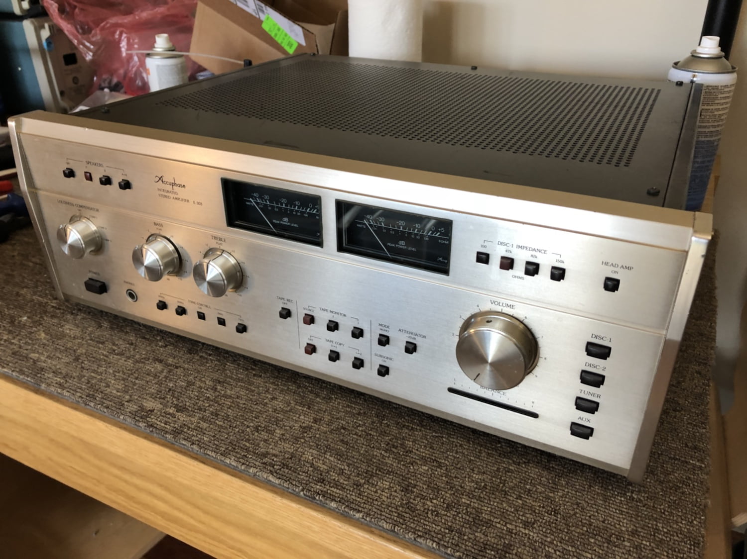
Accuphase E-303 Specifications
As usual, specs come courtesy of HiFi Engine:
Power output: 130 watts per channel into 8Ω (stereo)
Frequency response: 20Hz to 20kHz
Total harmonic distortion: 0.08%
Damping factor: 80
Sensitivity: 0.125mV (MC), 2.5mV (MM), 160mV (line)
Signal to noise ratio: 72dB (MC), 86dB (MM), 100dB (line)
Output: 160mV (line), 1.3V (Pre out)
Load impedance: 4Ω to 16Ω
Semiconductors: 113 x transistors, 2 x IC, 18 x FET, 39 x diodes
Dimensions: 445 x 160 x 370mm
Weight: 20kg
Problems With This Accuphase E-303
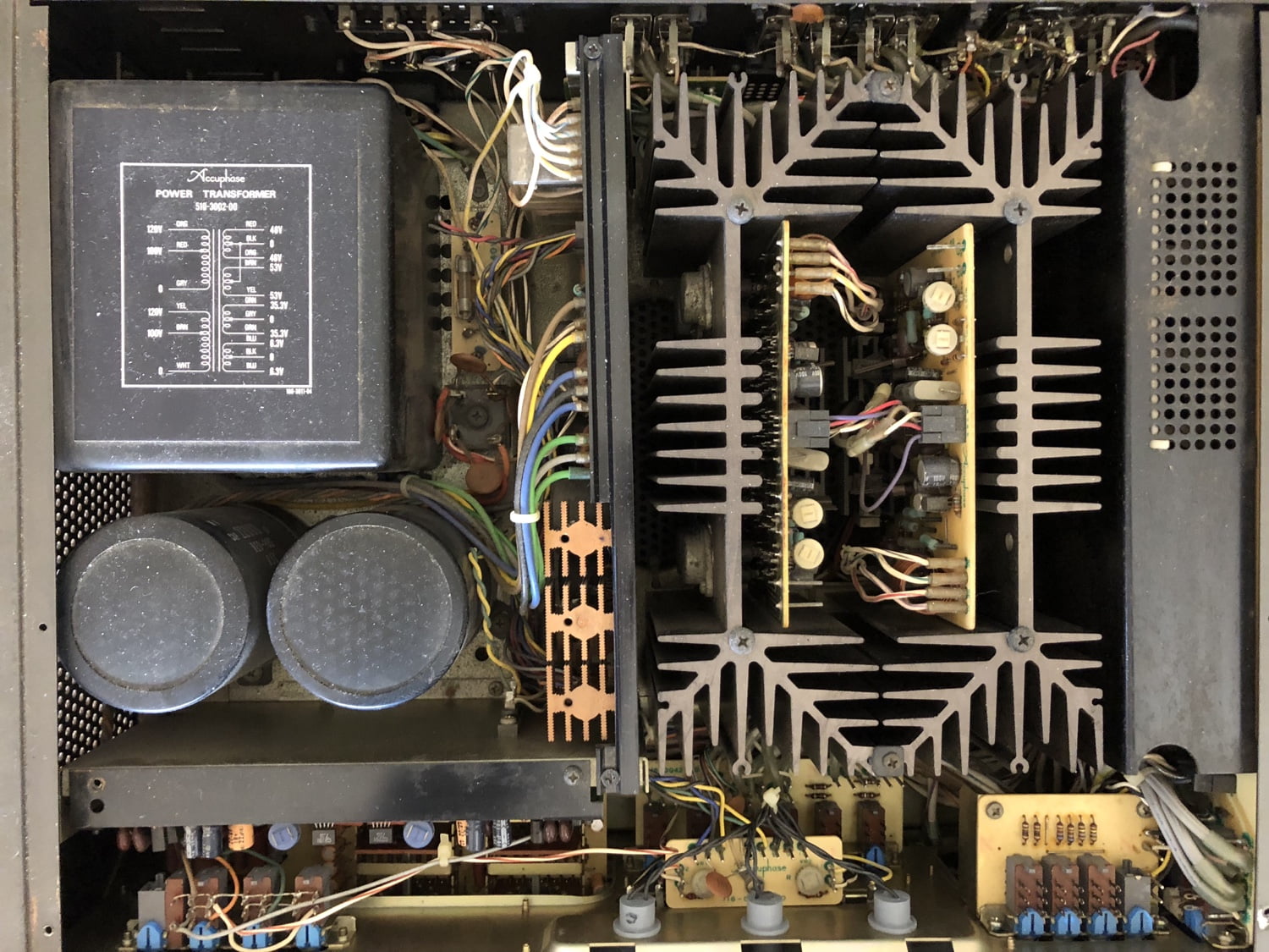
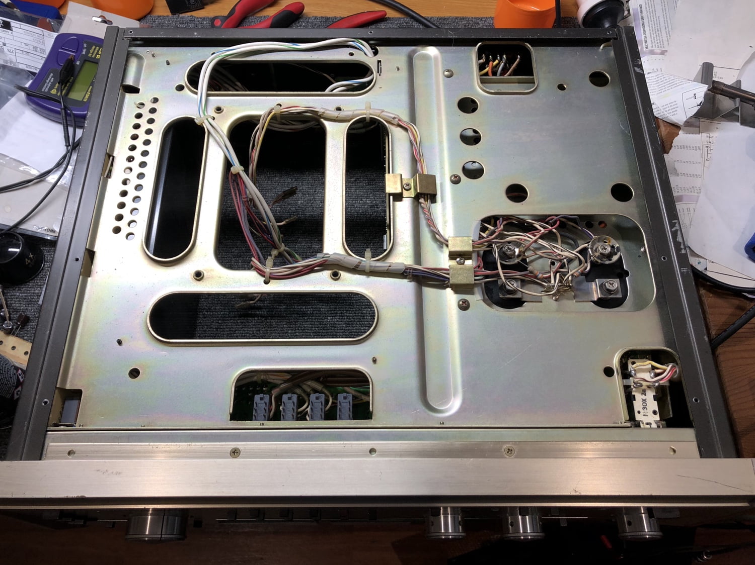
This E-303 had many issues, mostly due to neglect and poor quality previous work. Here’s a summary of what my inspection revealed:
- She’d been neglected and had sat in a shed somewhere for a long time.
- She’d been dropped at some point and many of the back panel connectors had been epoxied back in place.
- Someone had attempted to repair a broken mute relay, failed and then taken the mute relays out of circuit by cutting the power wires to the board.
- She was filled with dust, dirt
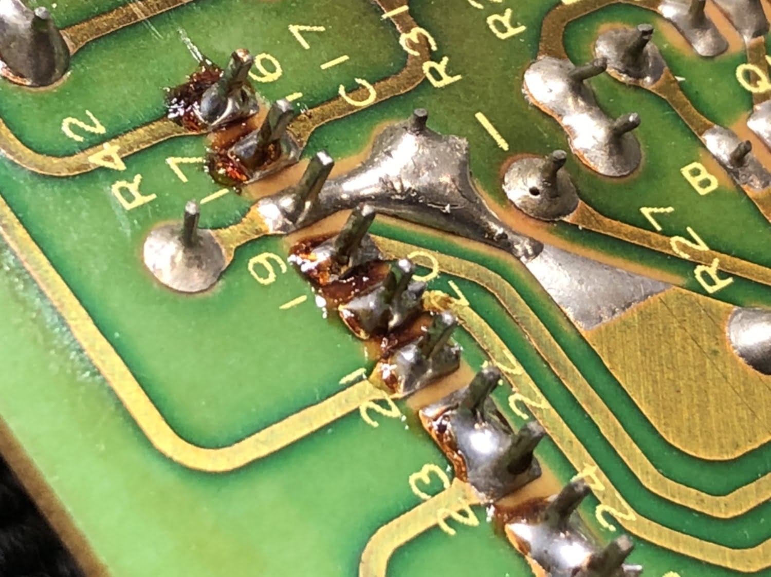
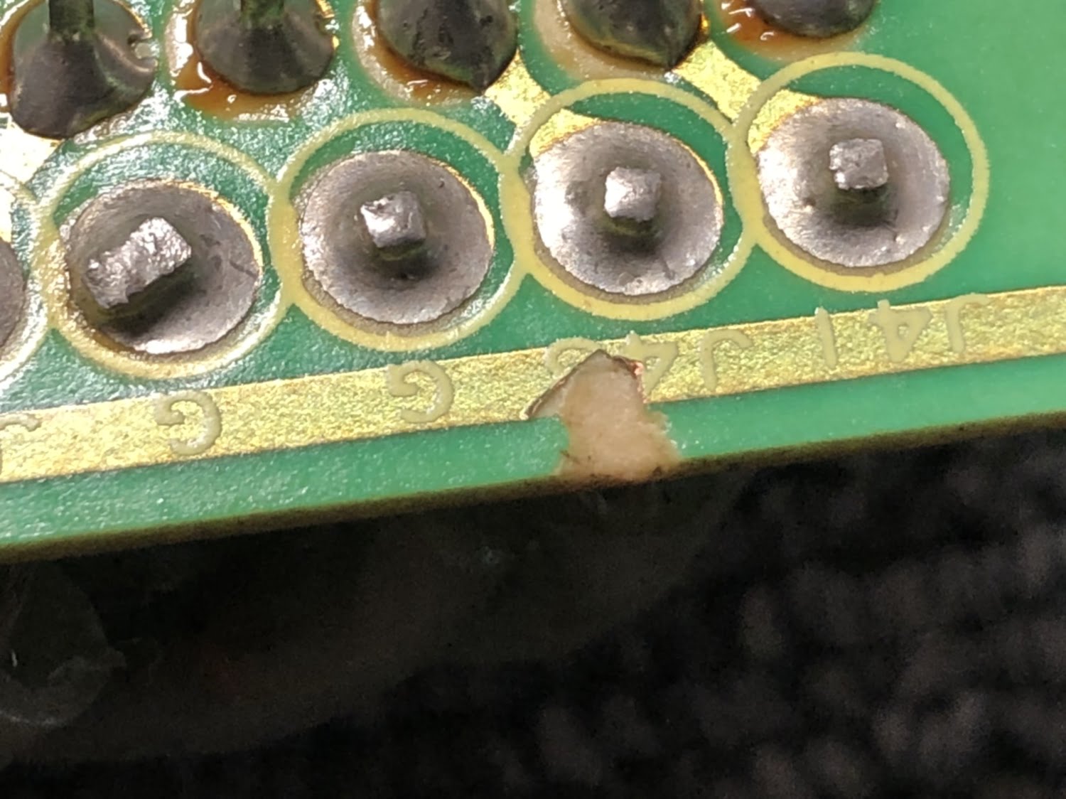
- There were several bad connectors and many dry joints
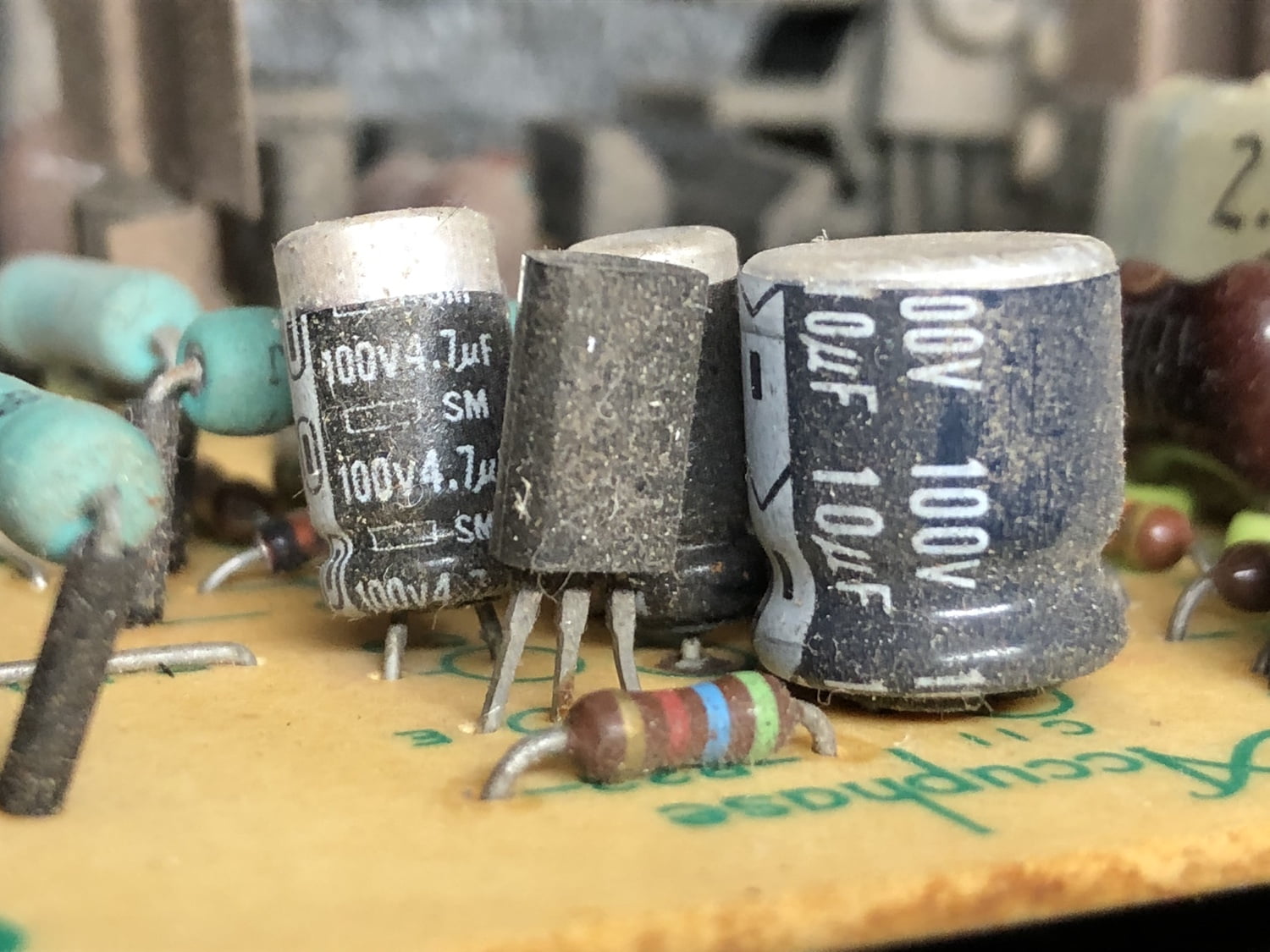
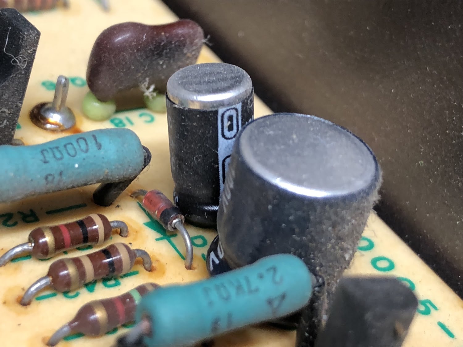
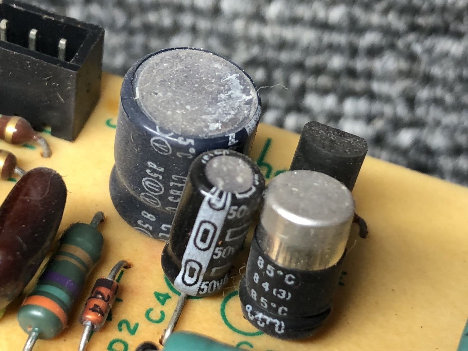
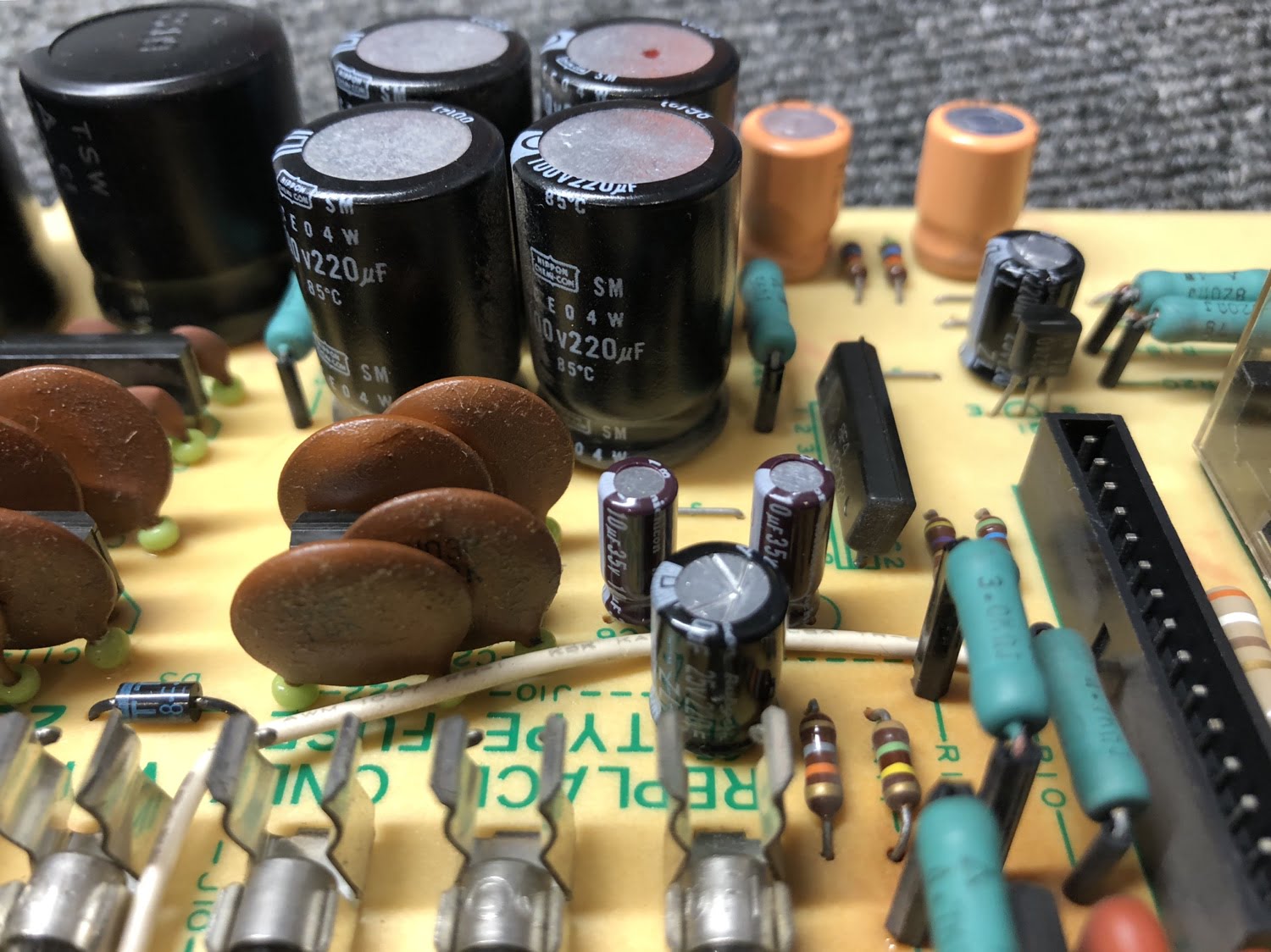
- Many capacitors needed replacement
- All adjustments were way out with massive DC offsets in both channels
- Some intermittent popping sounds in one channel
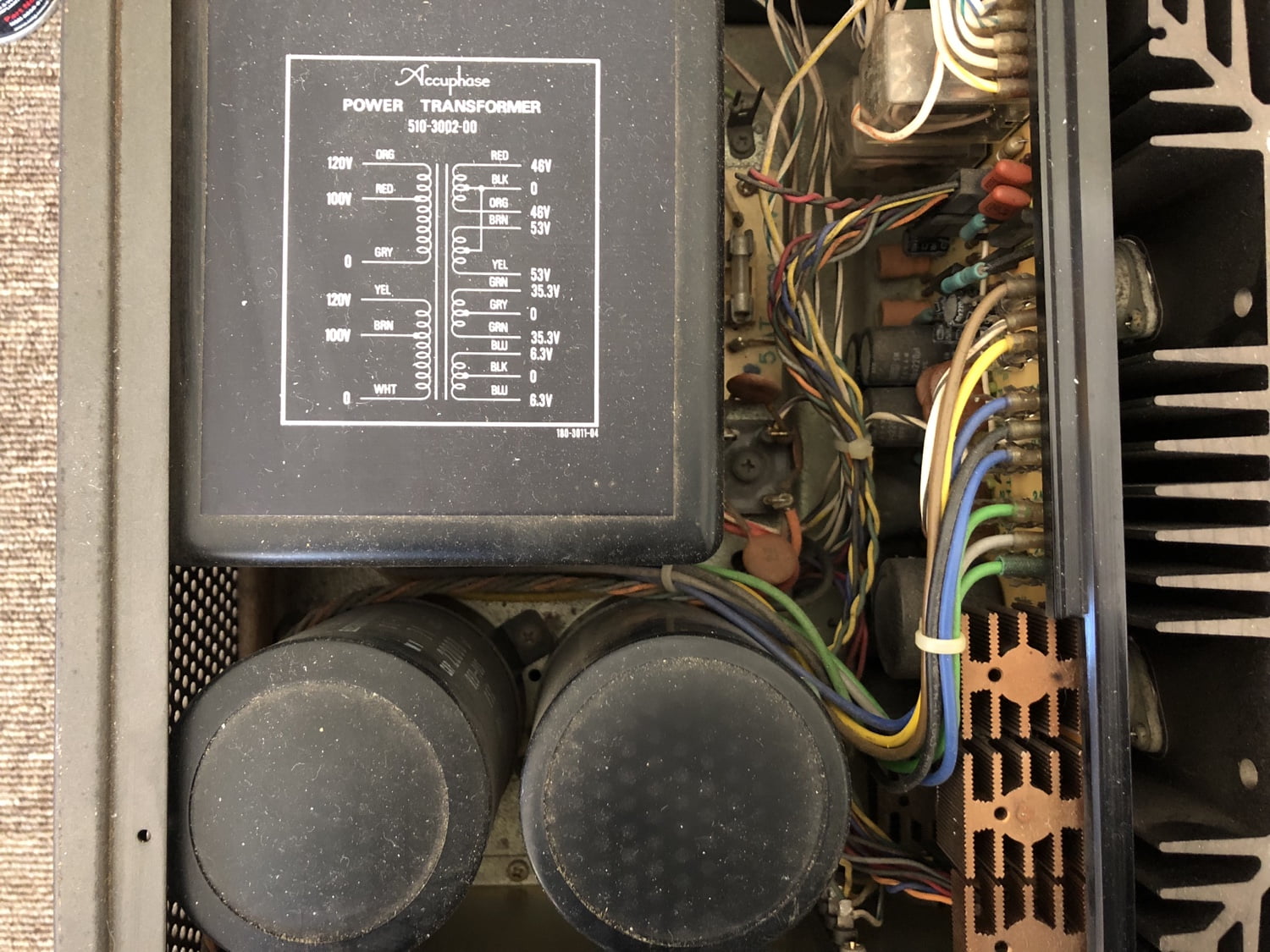
Clearly this E-303 needed significant TLC. Note though that each job is different and this one had a budget limit. The brief was repair and overhaul as necessary. It was not a full restoration and therefore many good original parts remain.
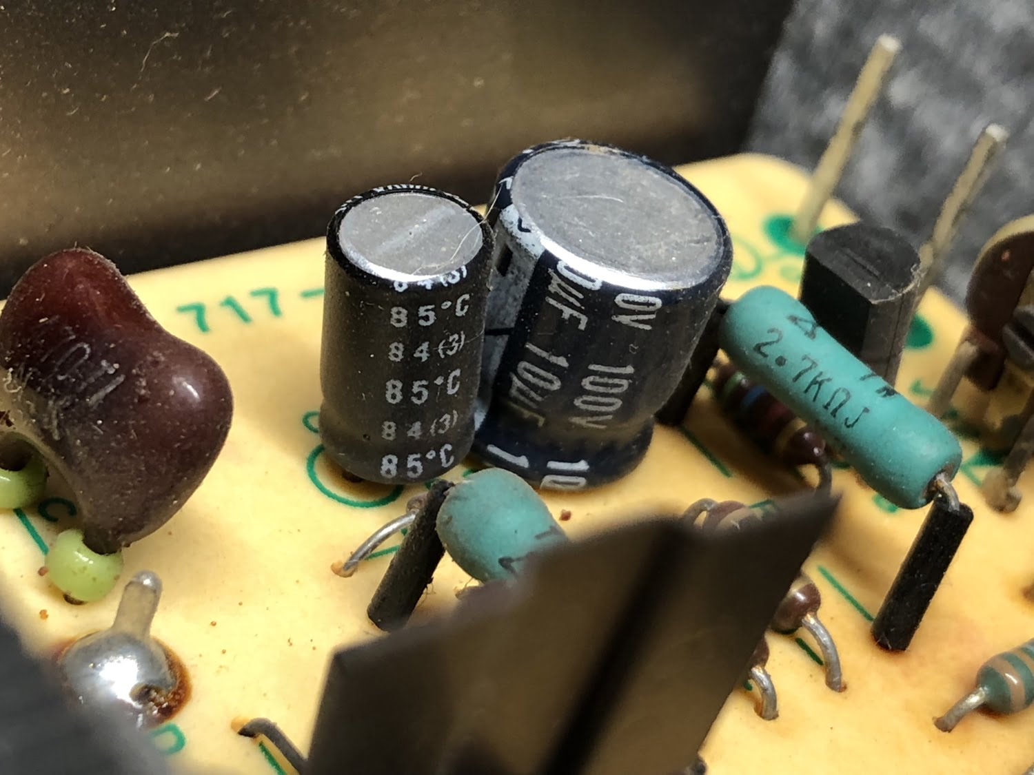
Overhaul
As usual, I start with the low hanging fruit and work from there. I replace bad caps, look at switches and controls, connectors, soldering, relays and so on. As I work through each ‘fruit’, performance improves and I can focus on remaining problems.
Amplifier Modules
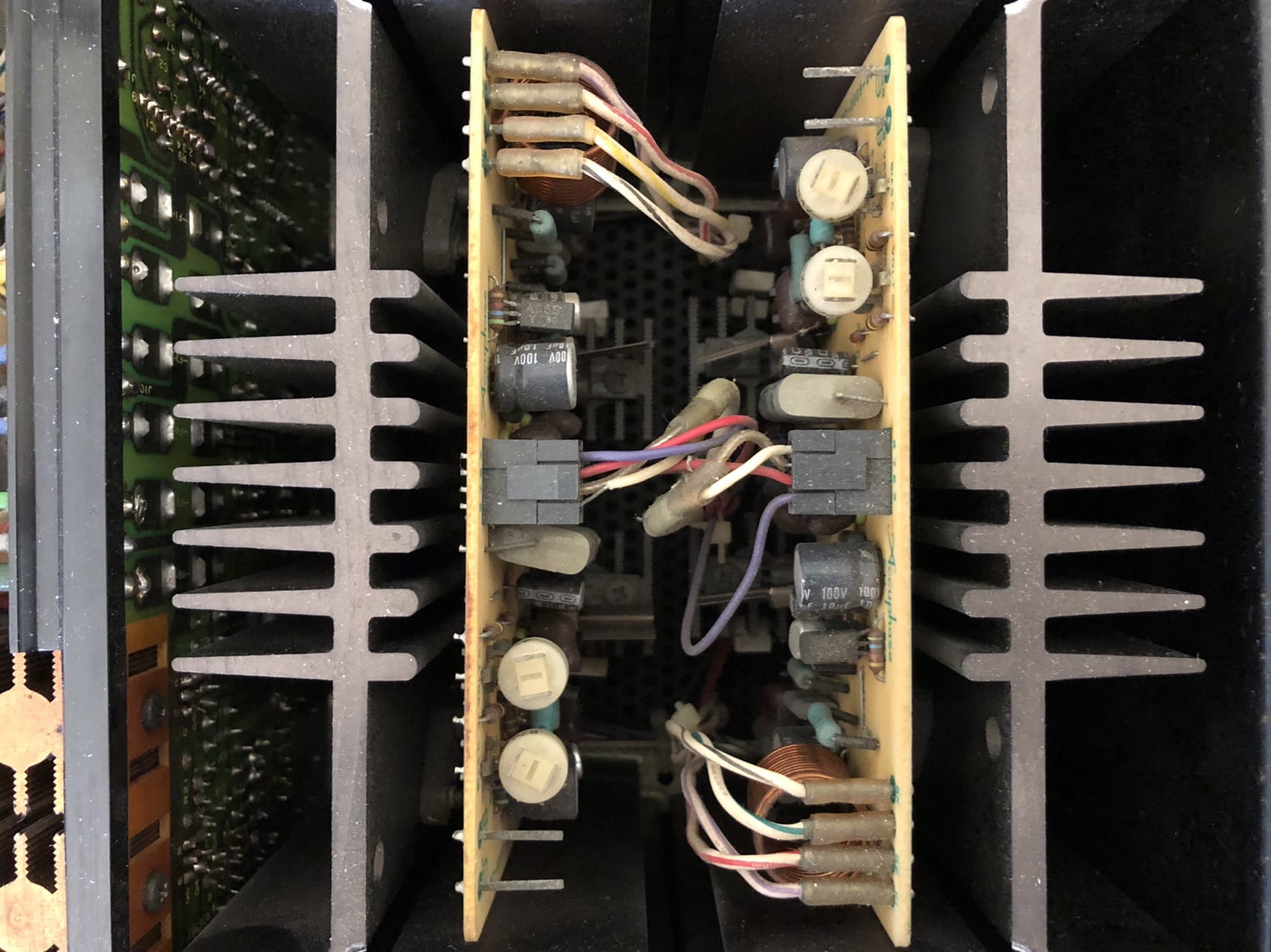
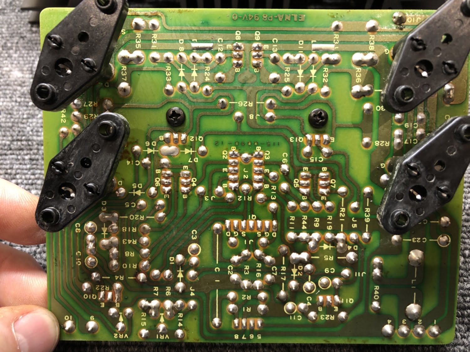
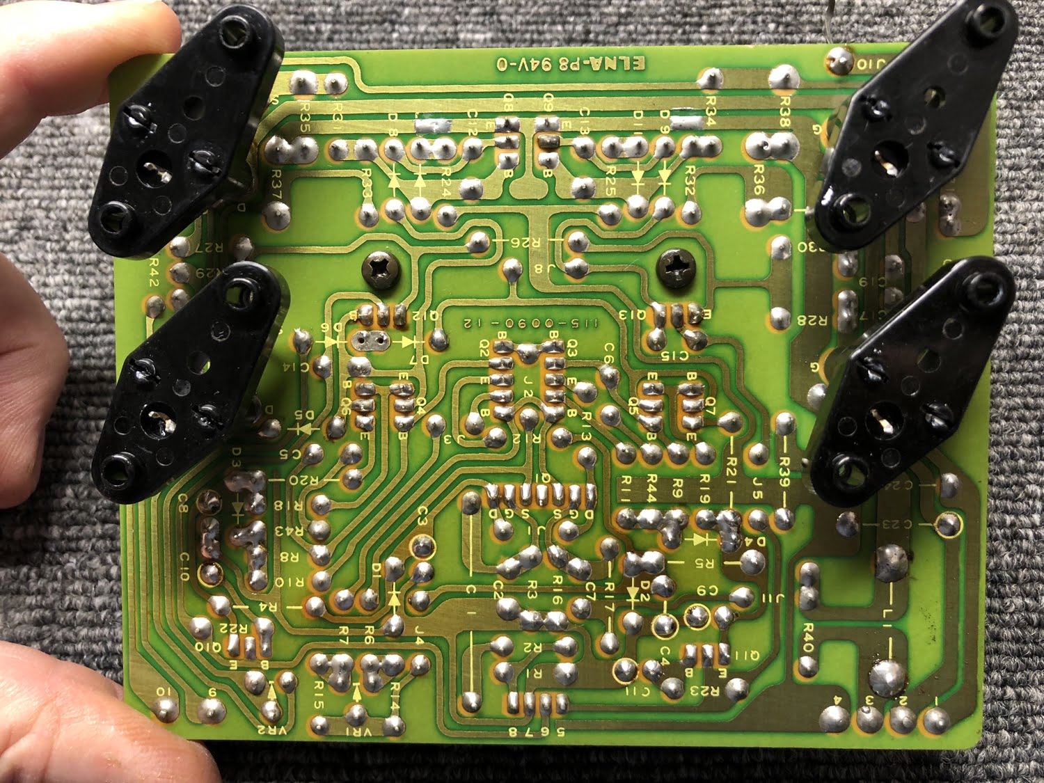
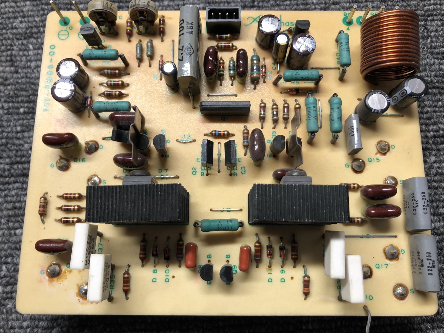
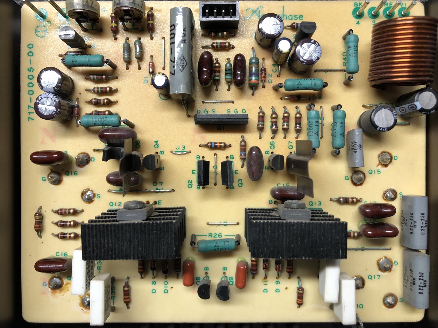
Let’s start with the amplifier modules, seeing as these get the hottest of any of the boards and are under the greatest ‘load’ shall we say.
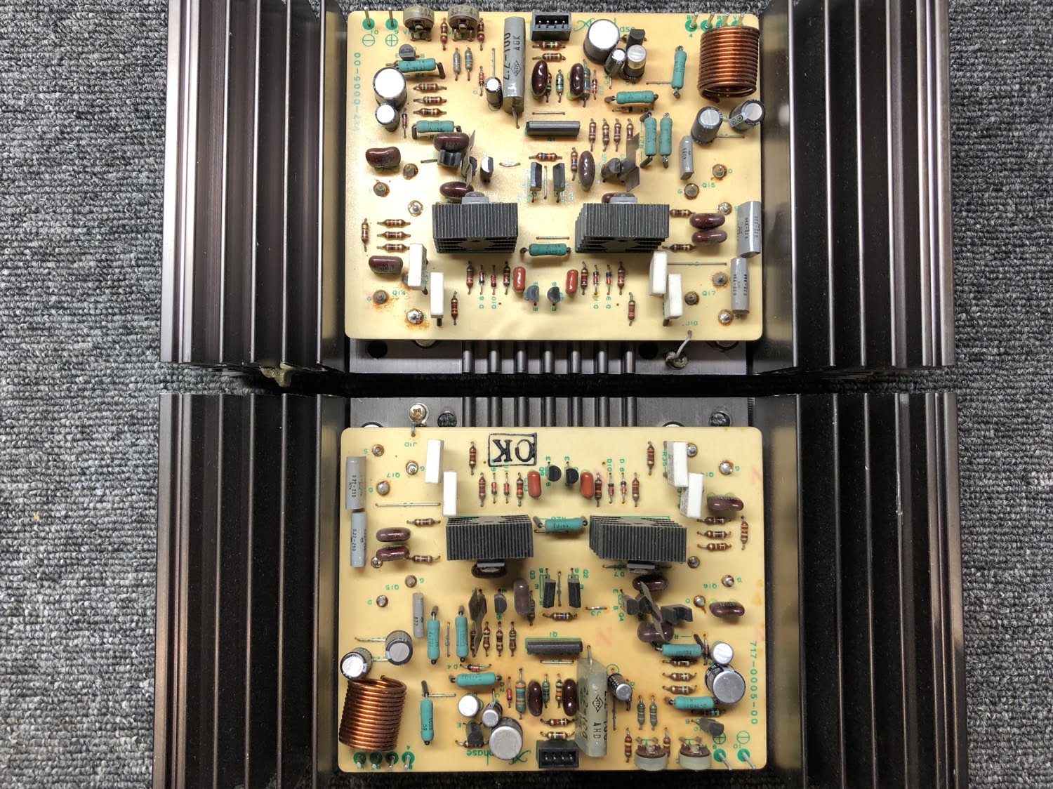
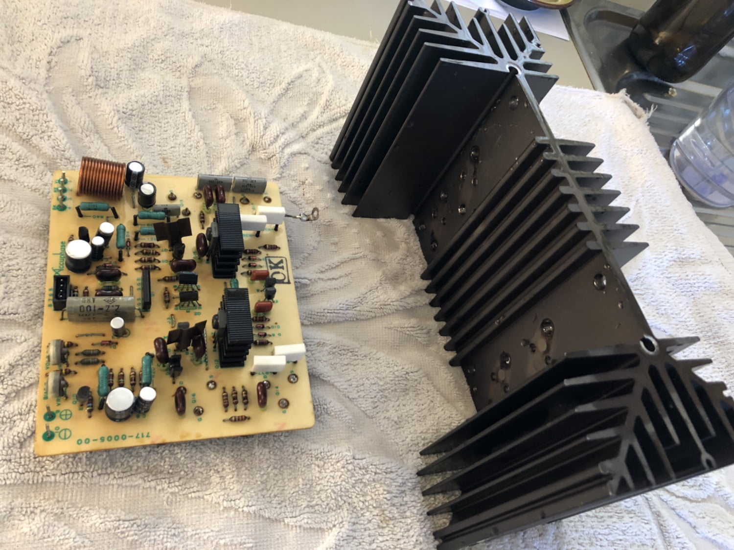
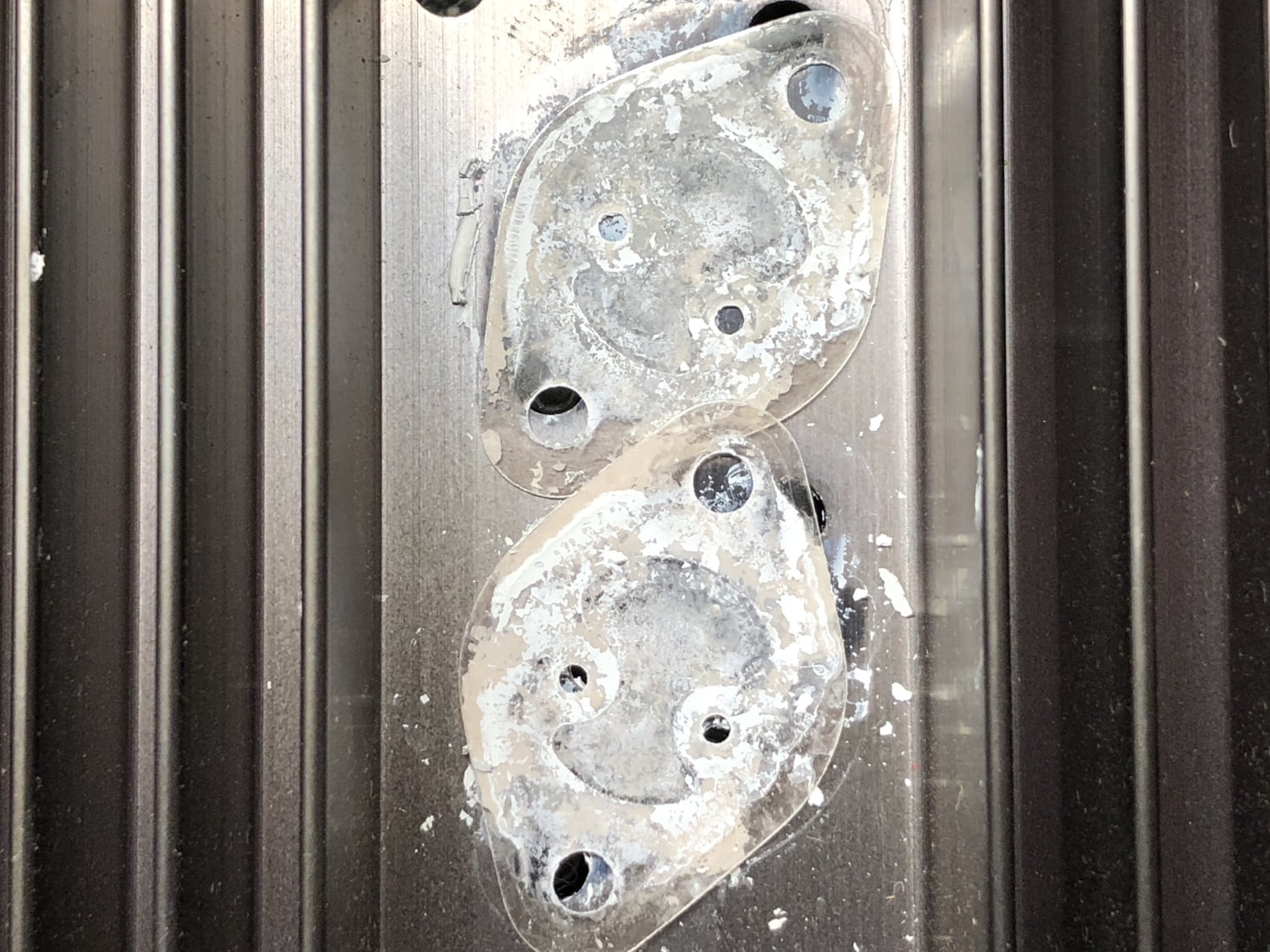
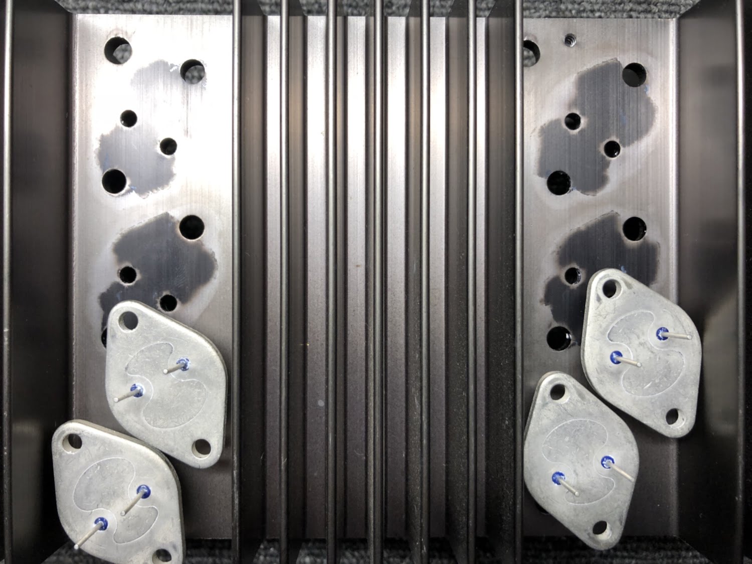
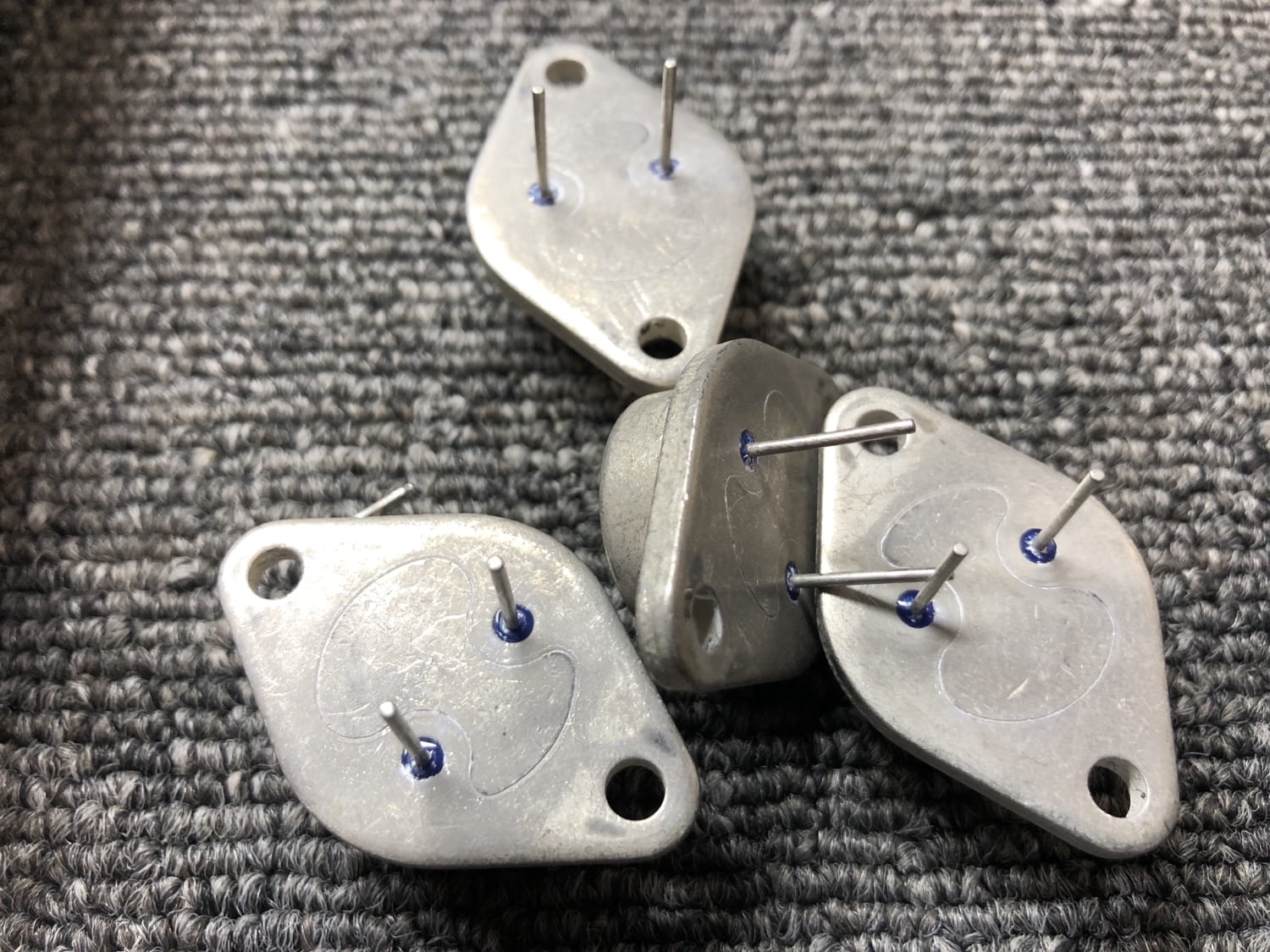
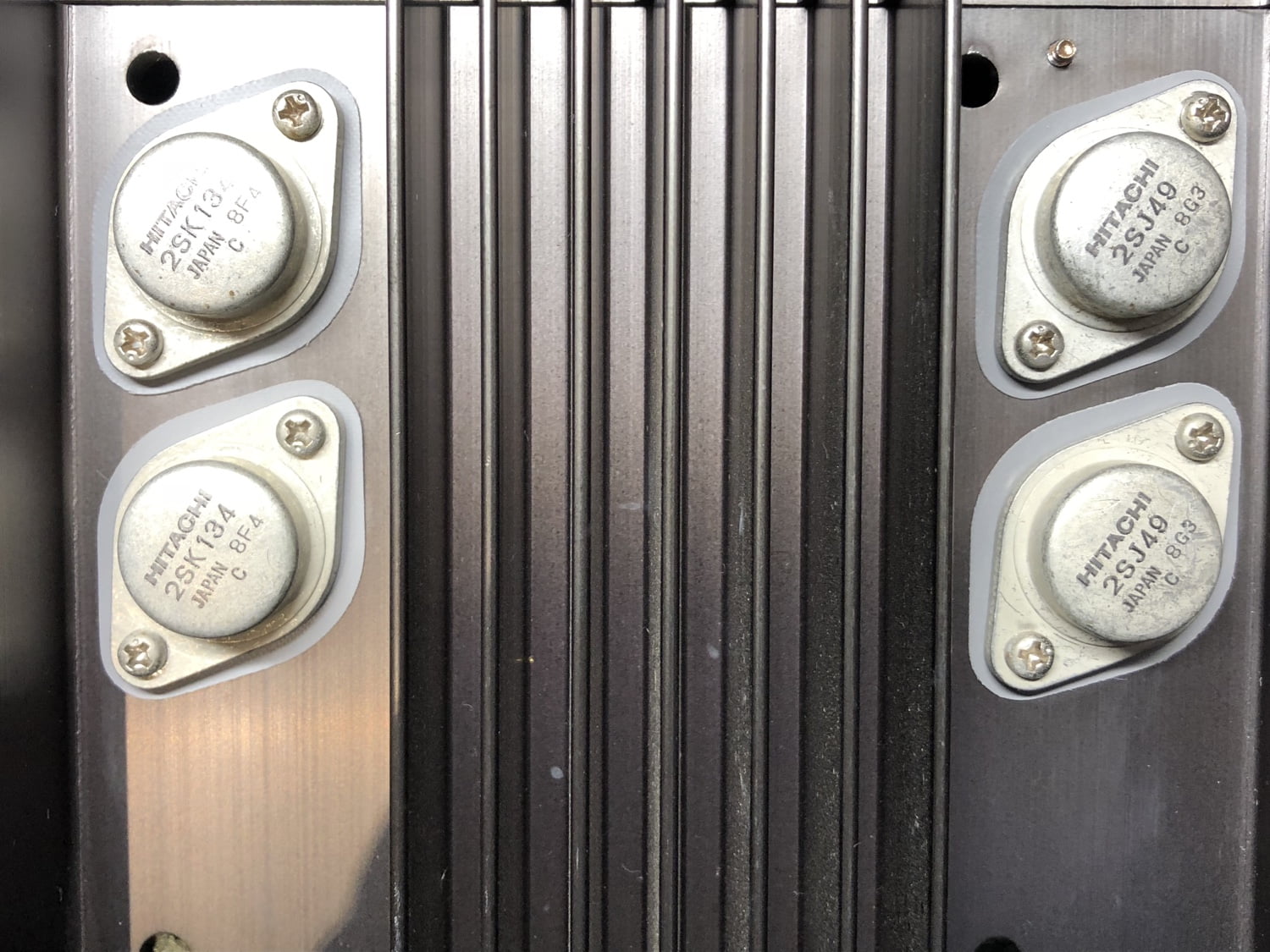
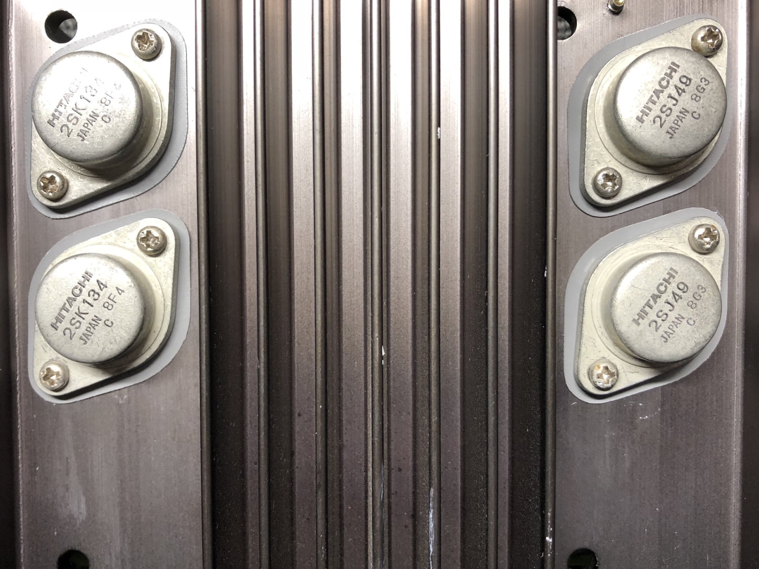
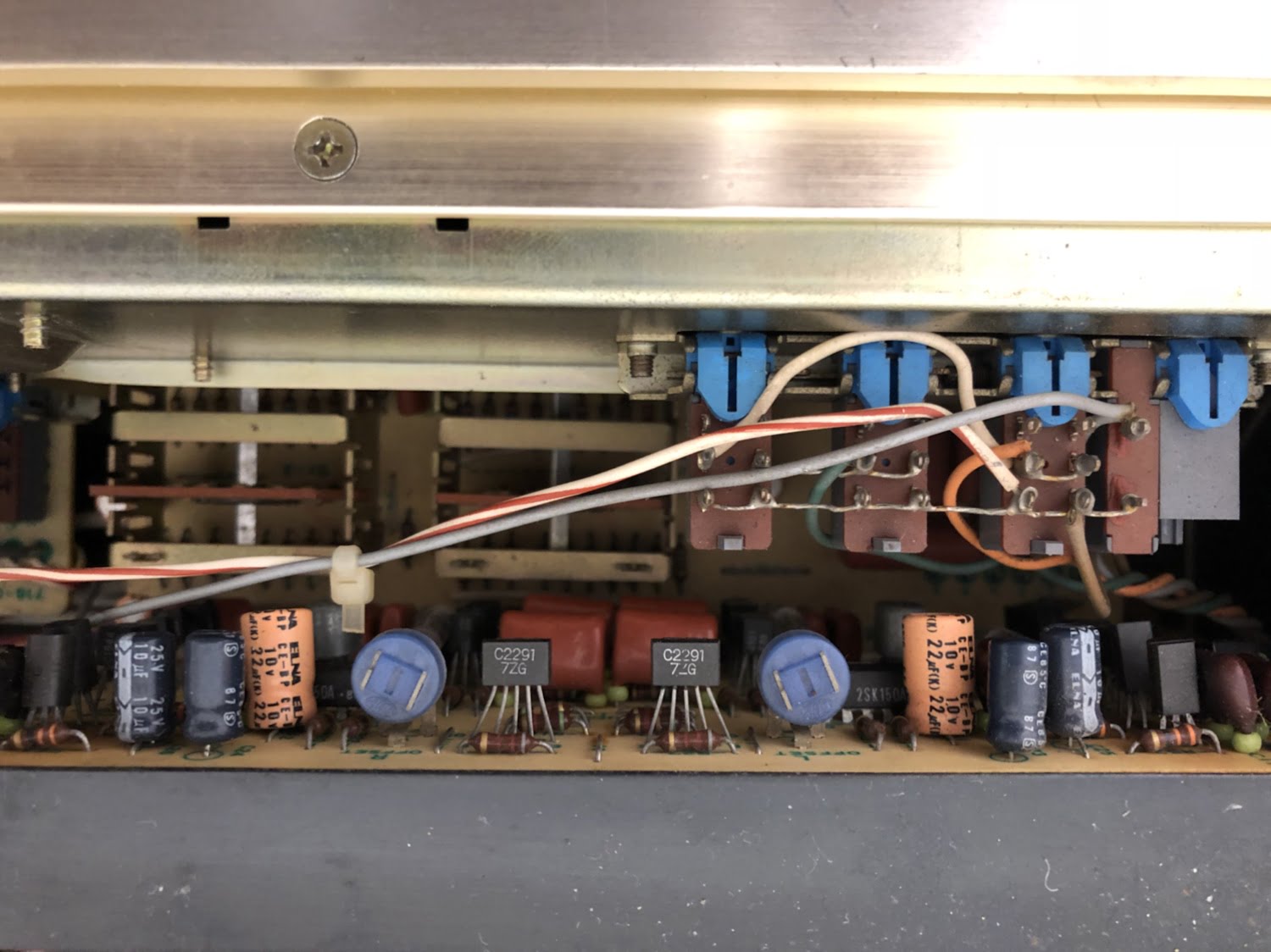
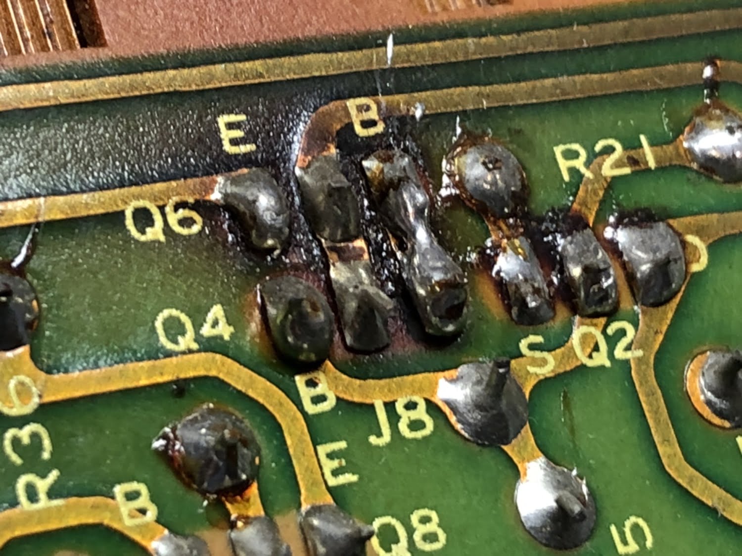
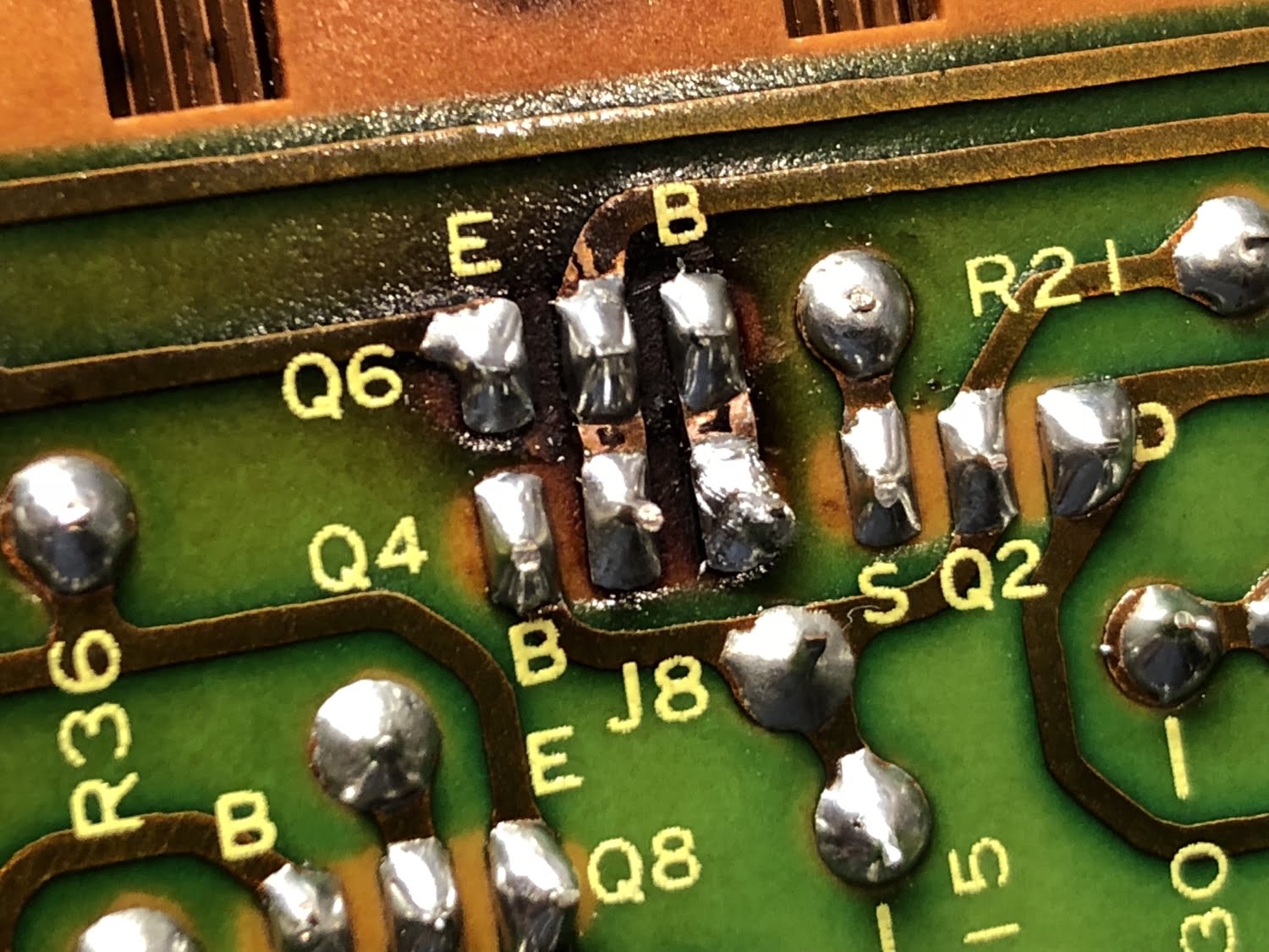
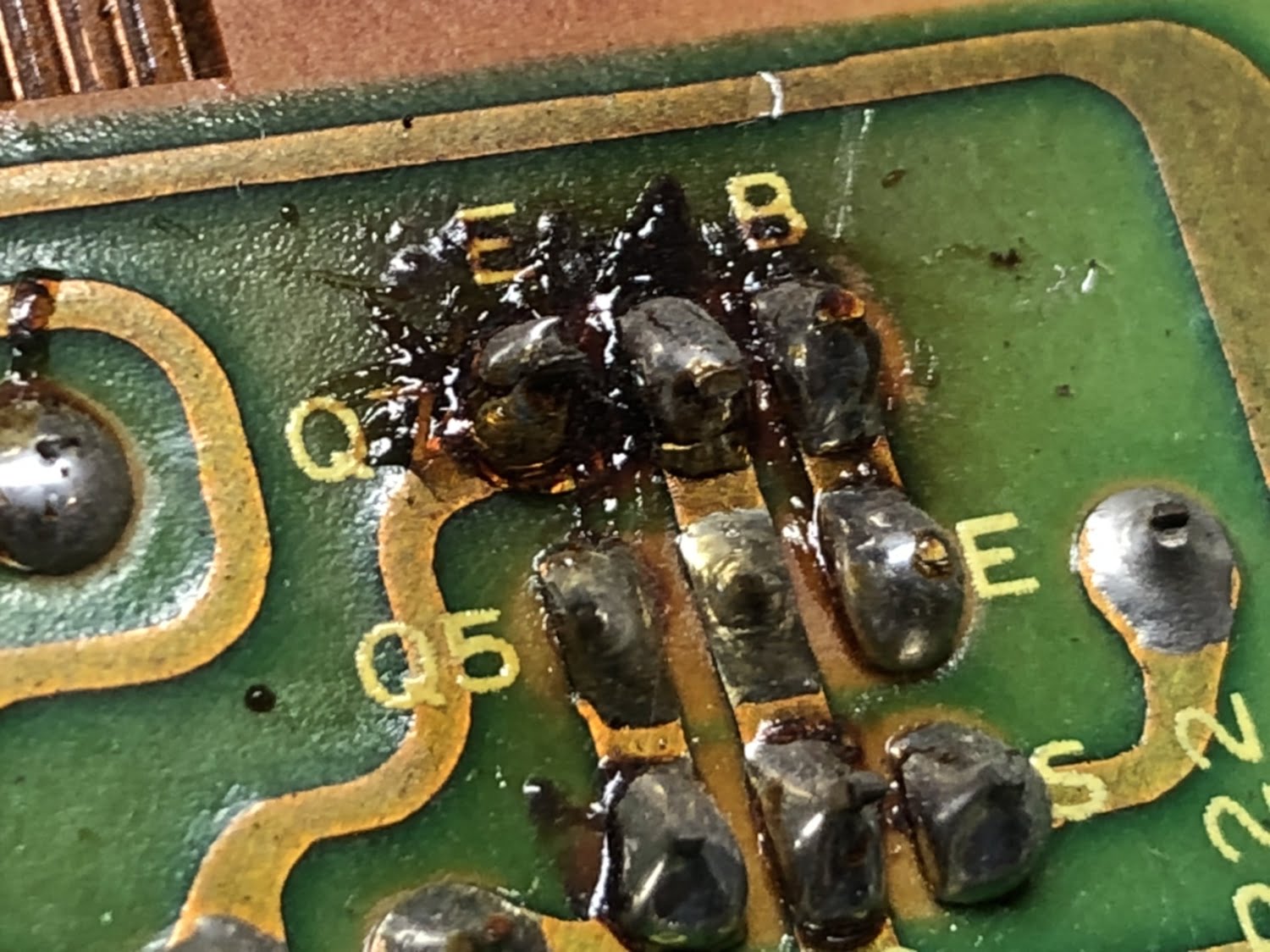
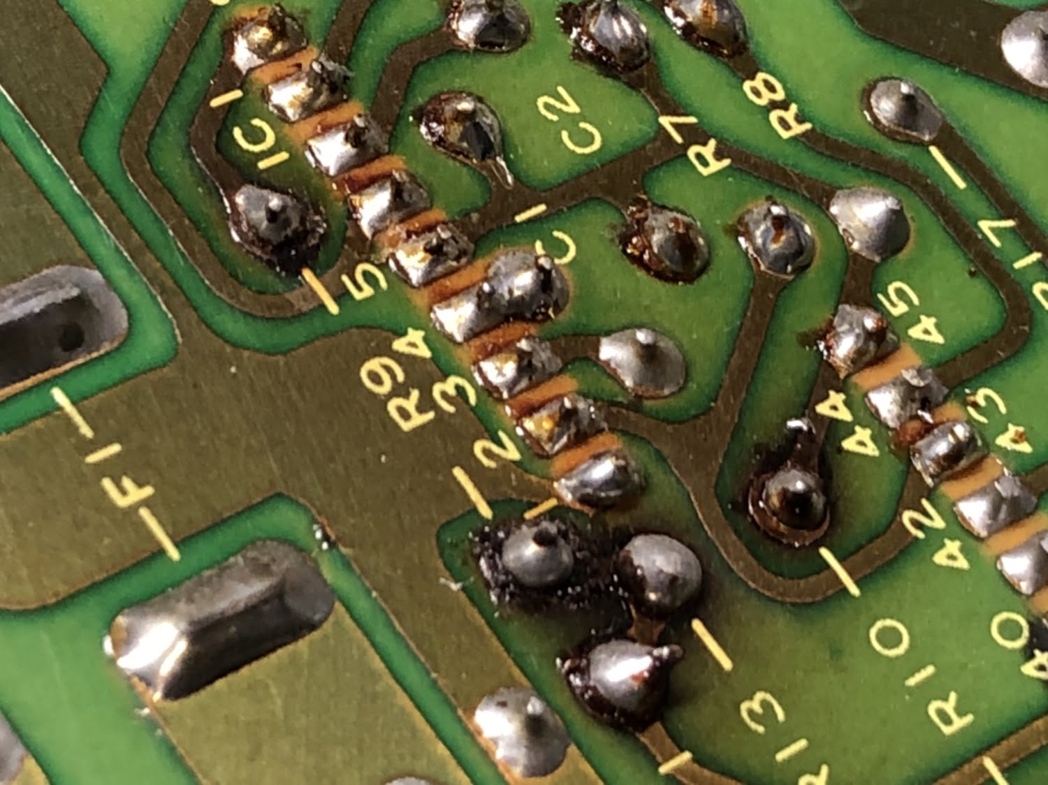
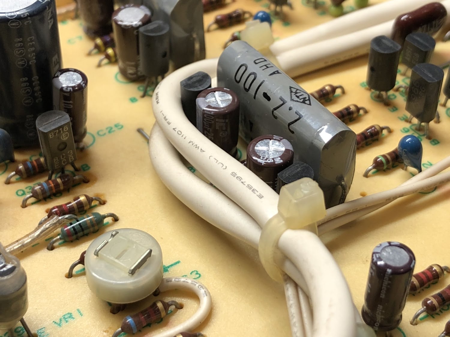
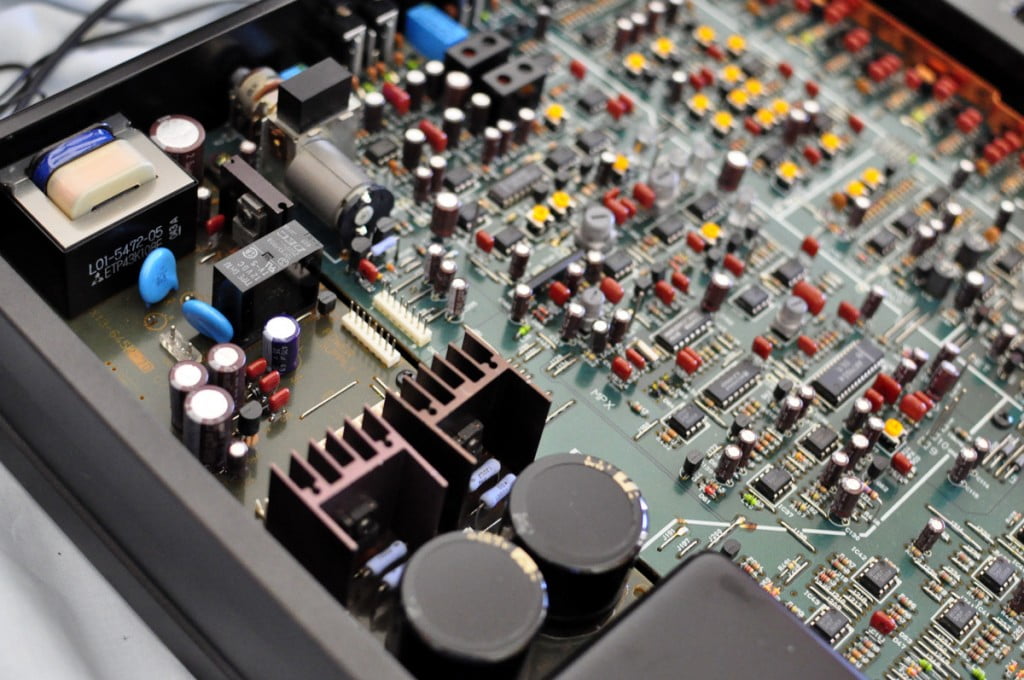
Turning attention to the boards, I repaired dry joints and replaced small capacitors. Note that this is not a full restoration, so many larger capacitors that measure well remain in place.
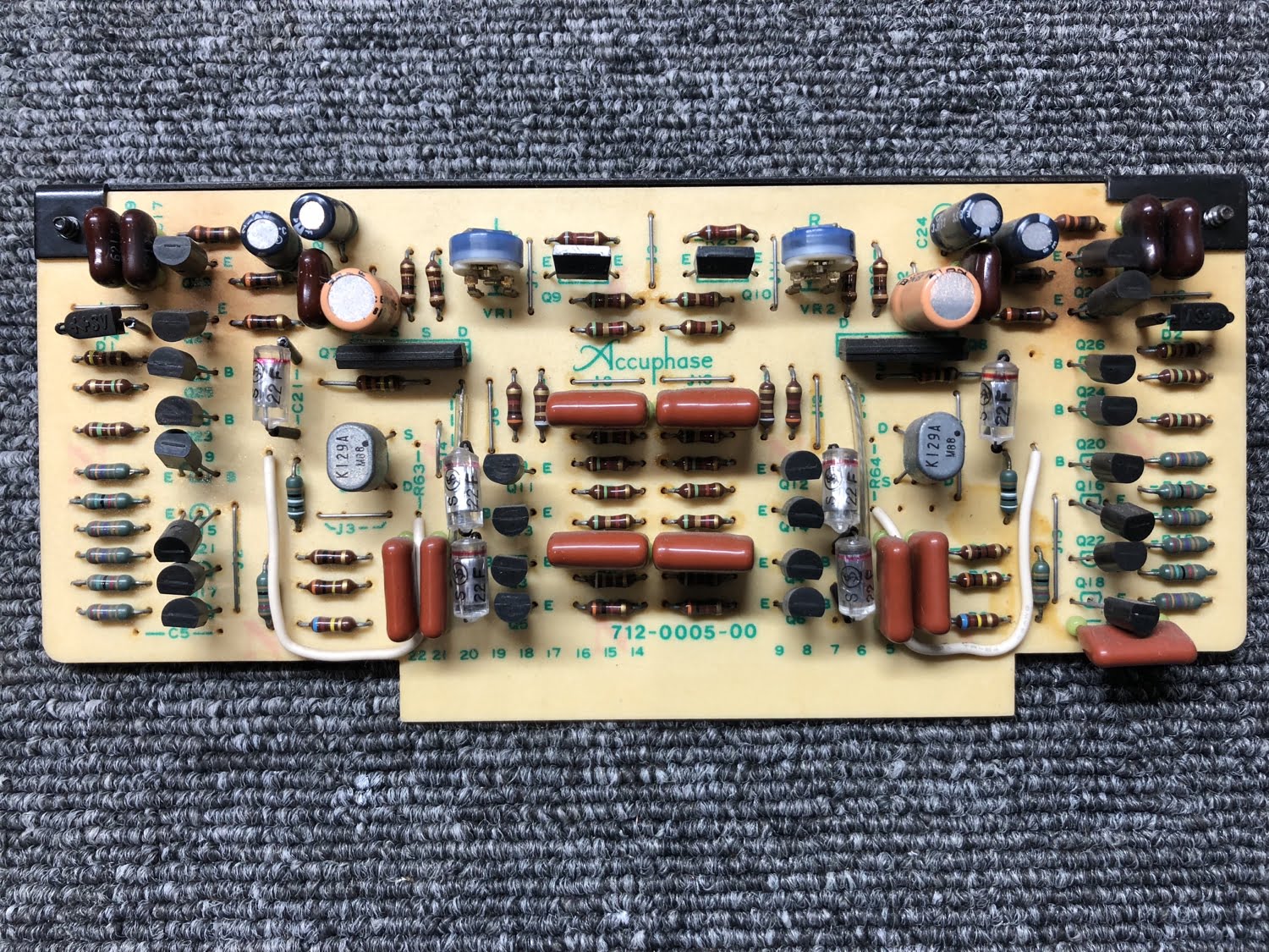
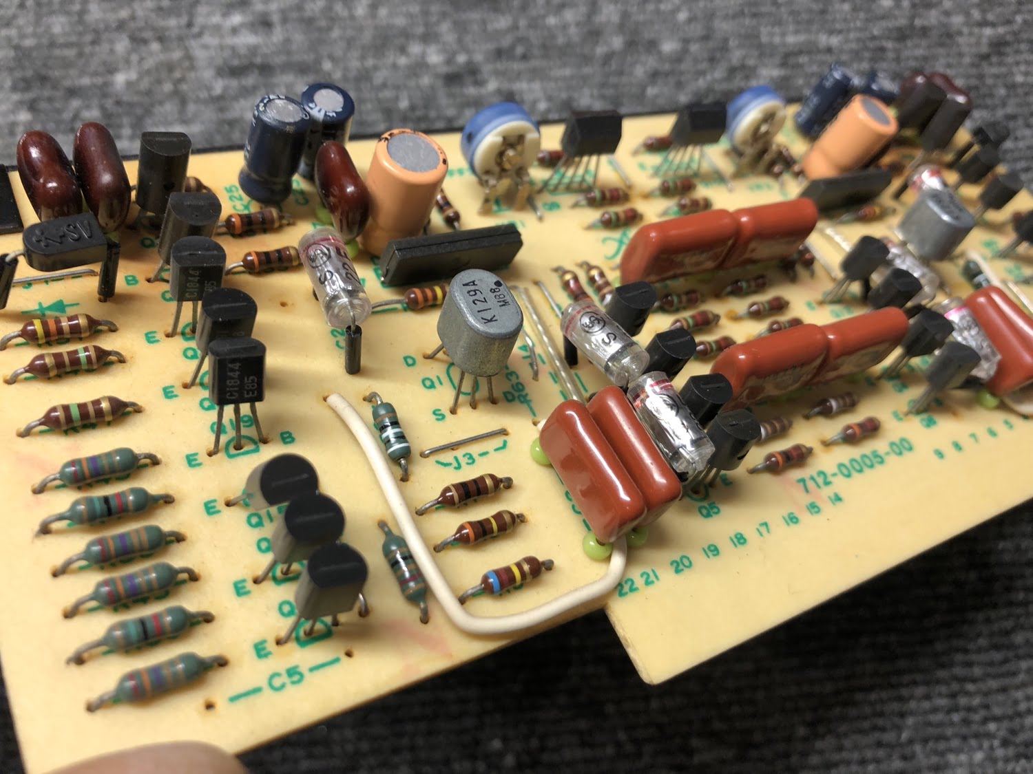
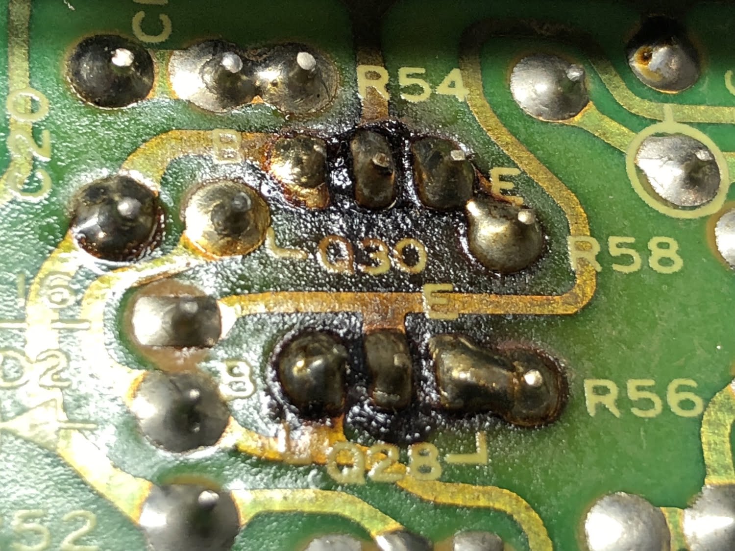
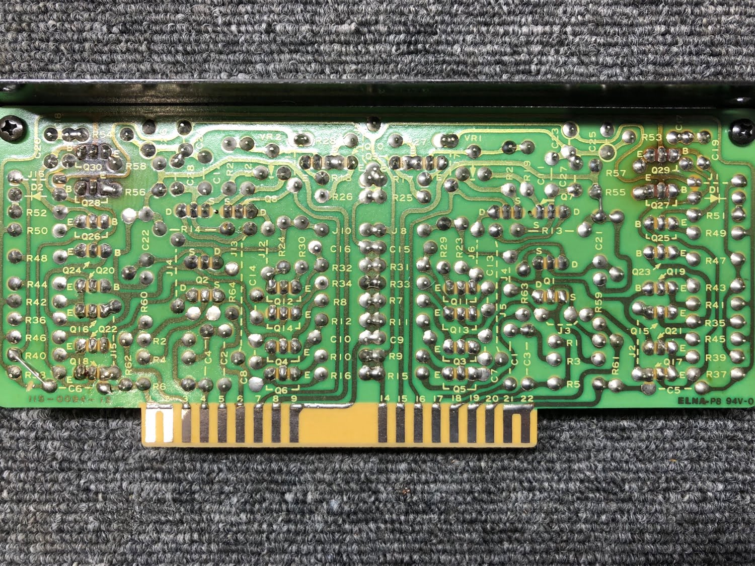
Tone and Buffer Amplifier
This board is an important one as all signals pass through it on the way to the power amplifiers.
Power Supply
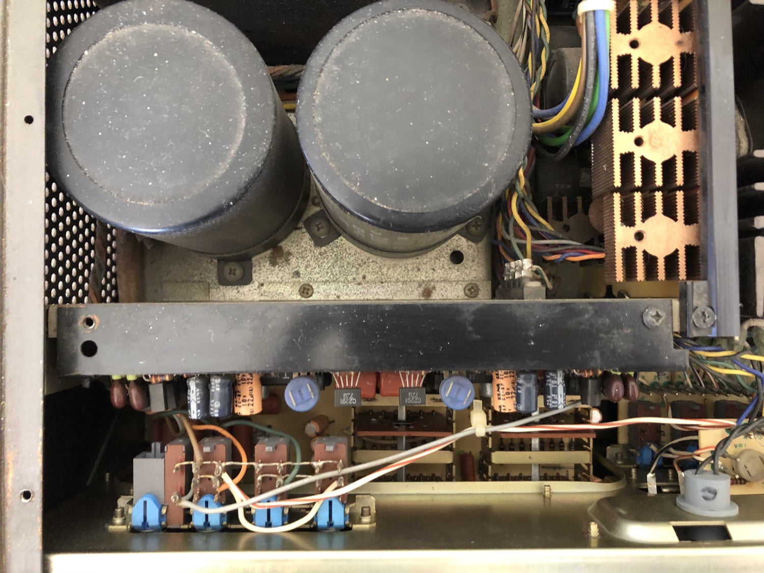
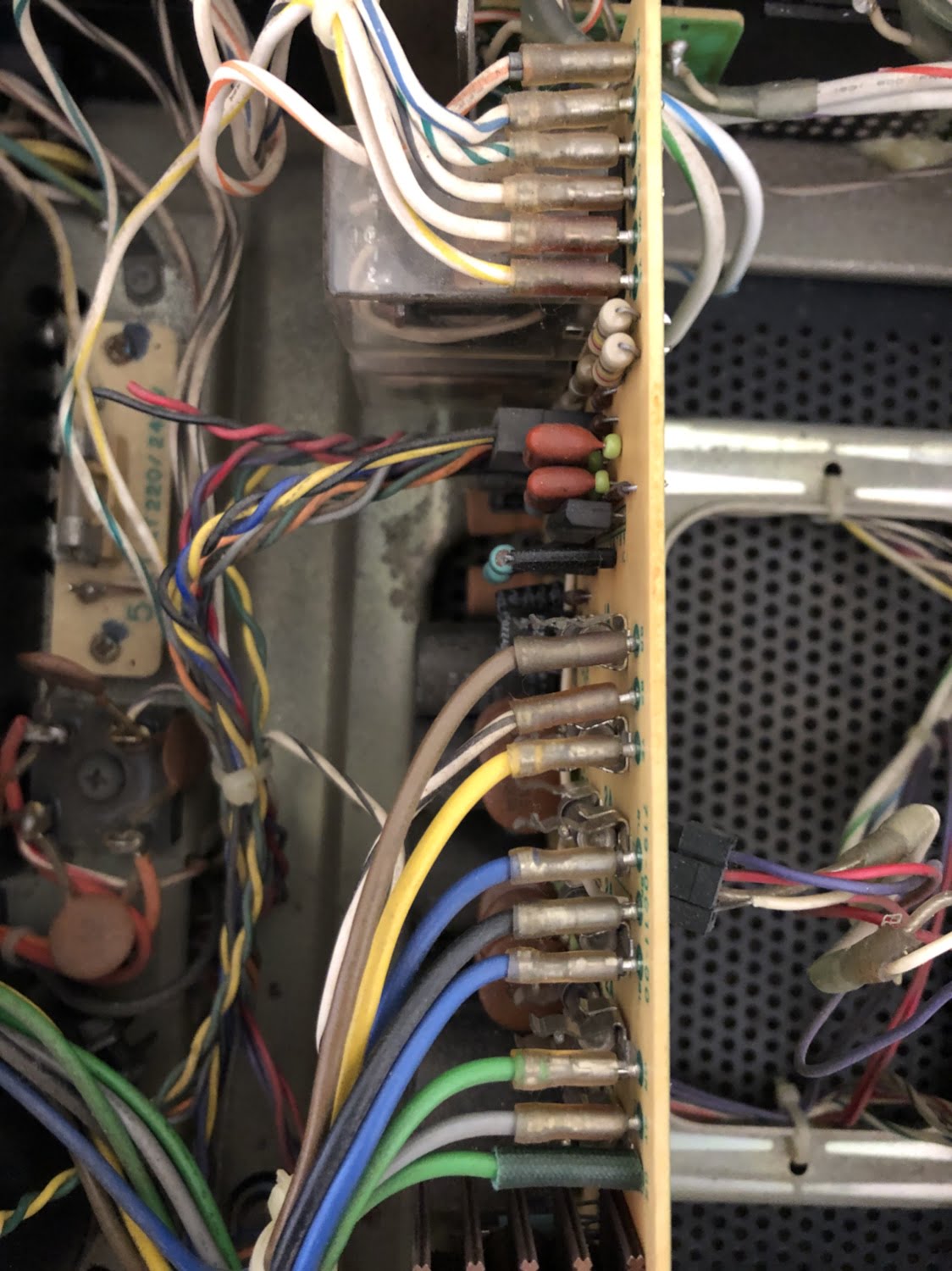
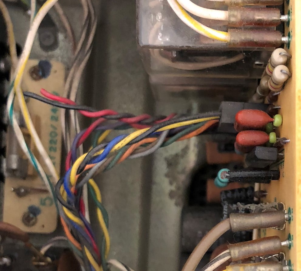
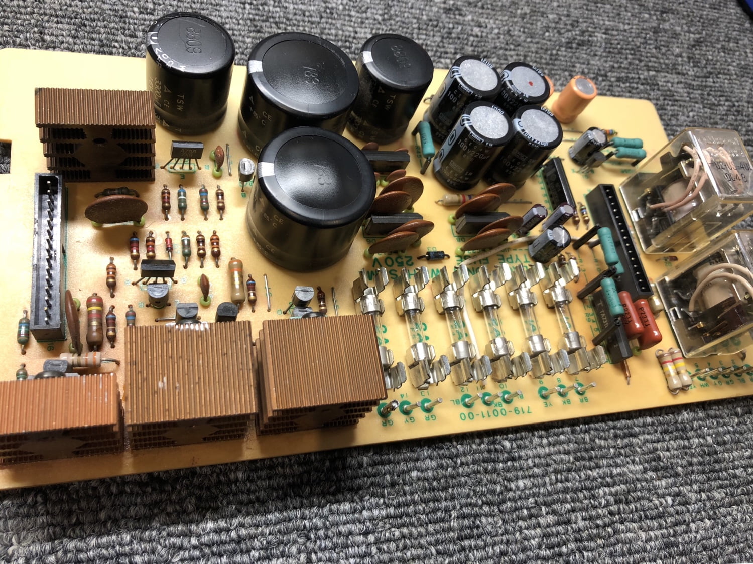
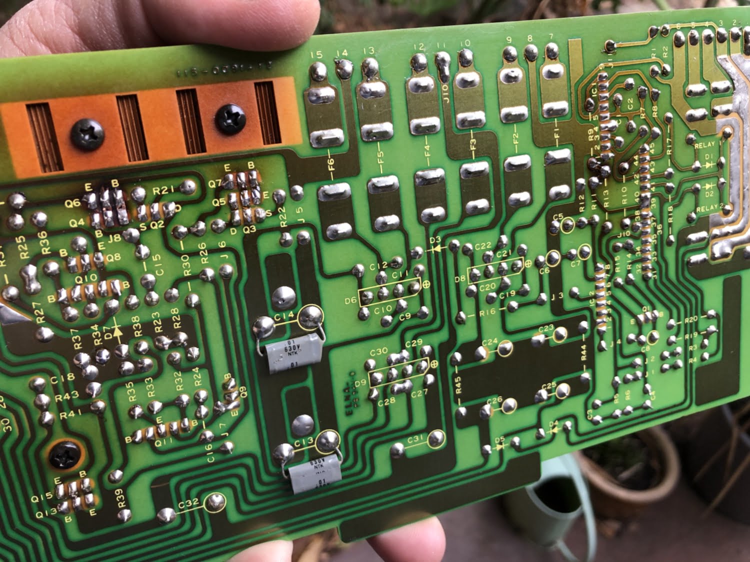
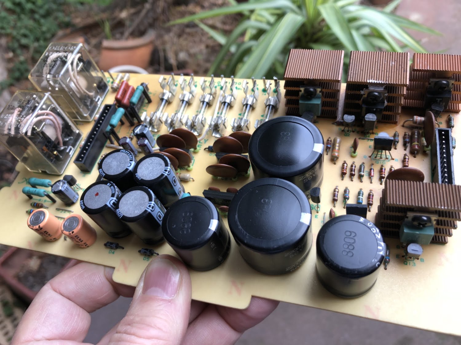
The power supply is one of the most import, if not the most important parts of any electronic device. It’s no different with this E-303.
Preamplifier Board
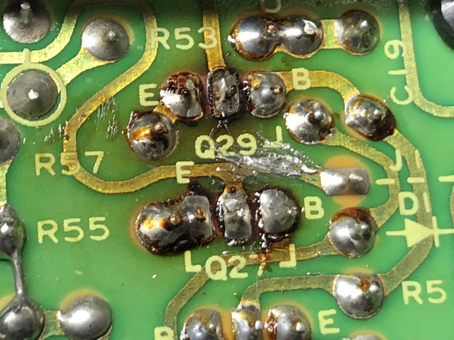
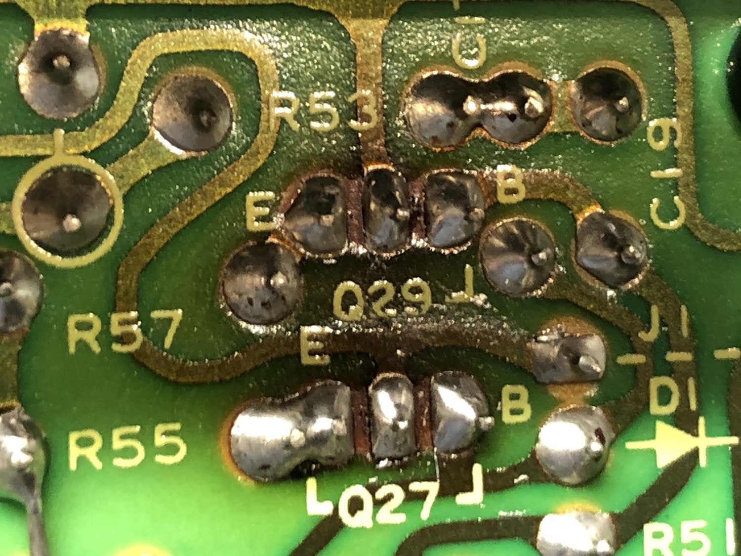
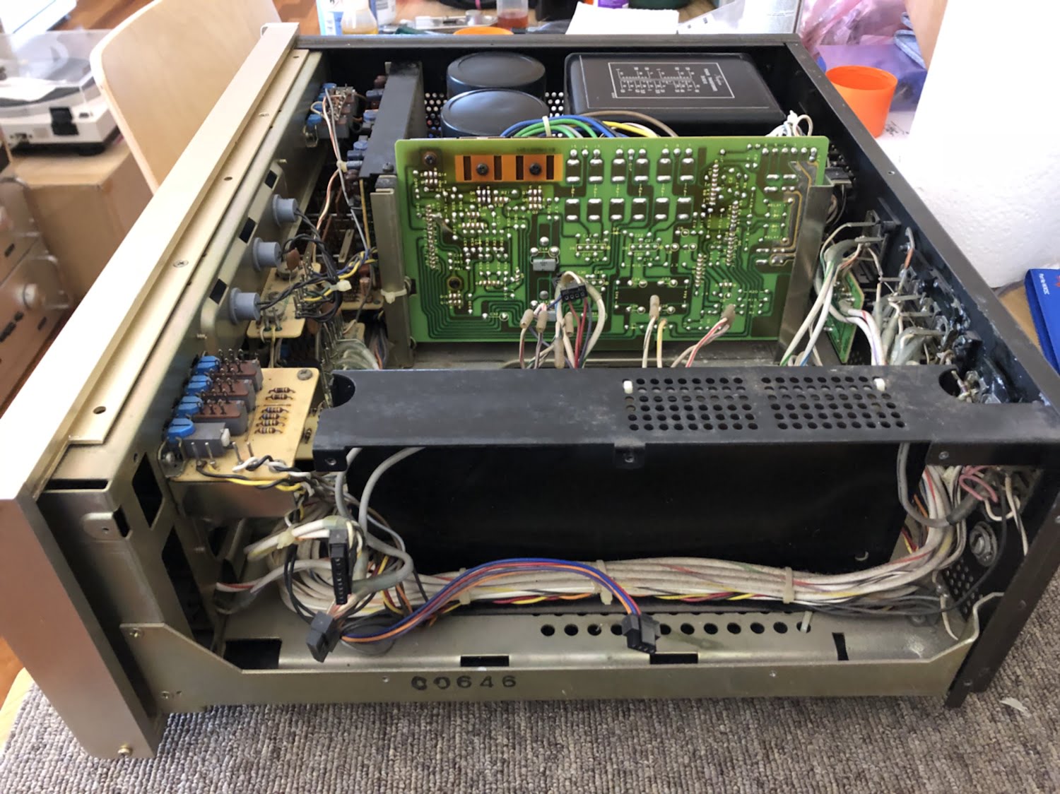
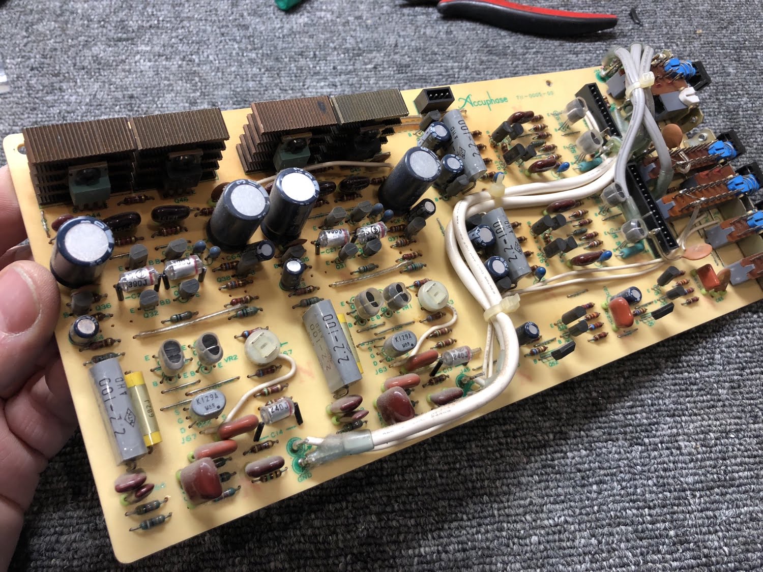
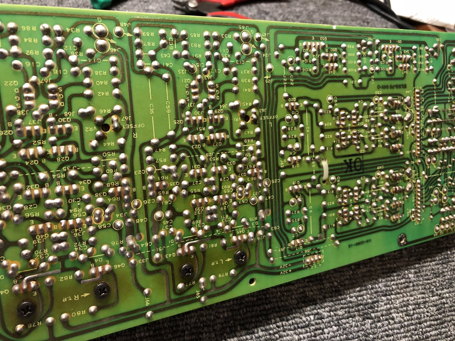
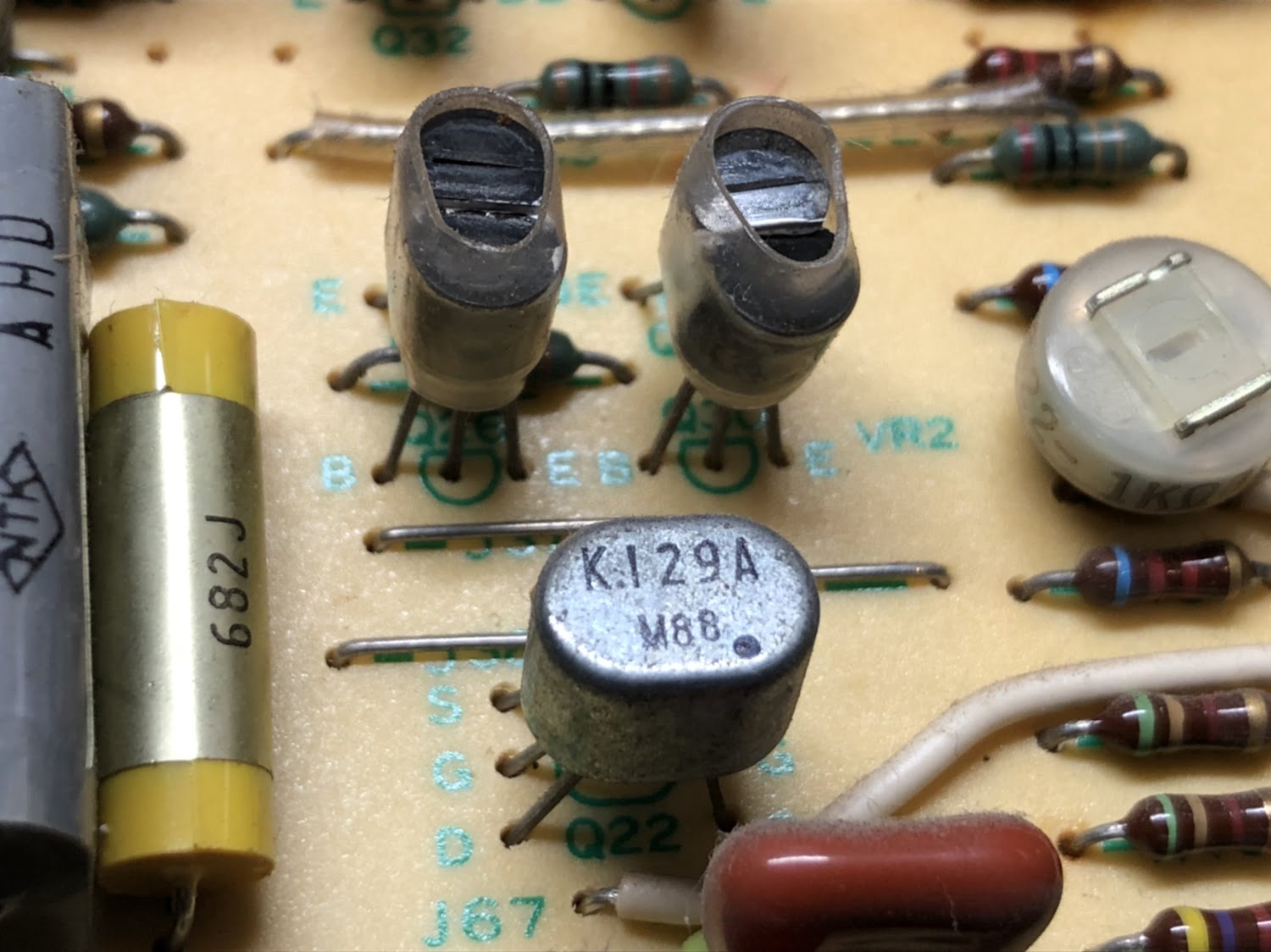
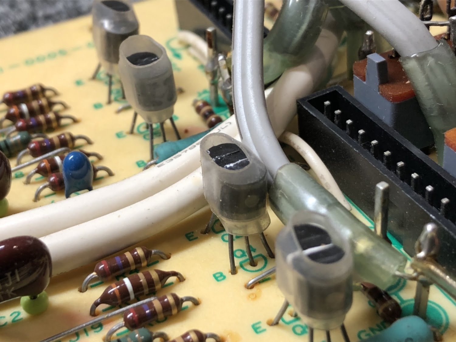
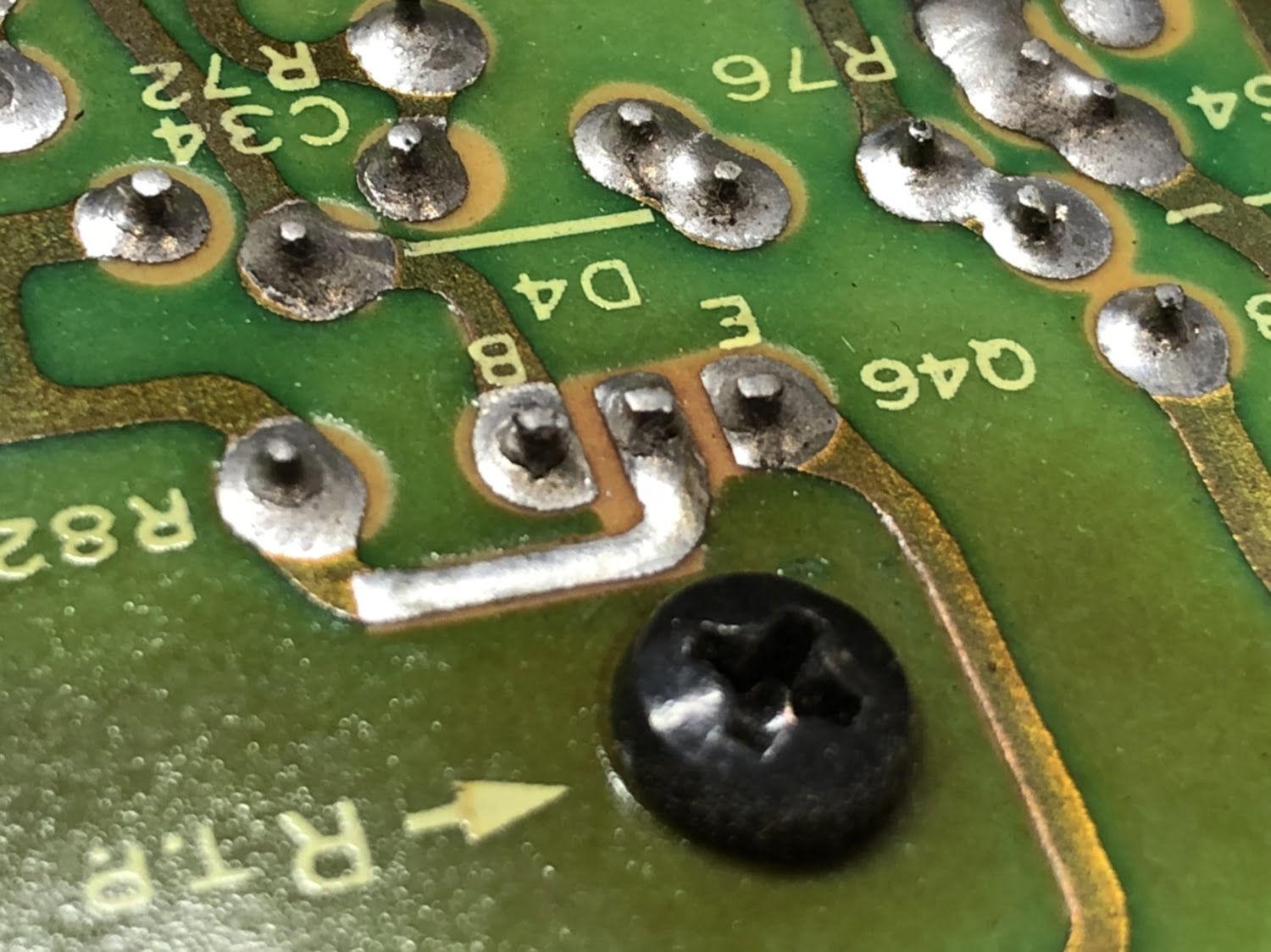
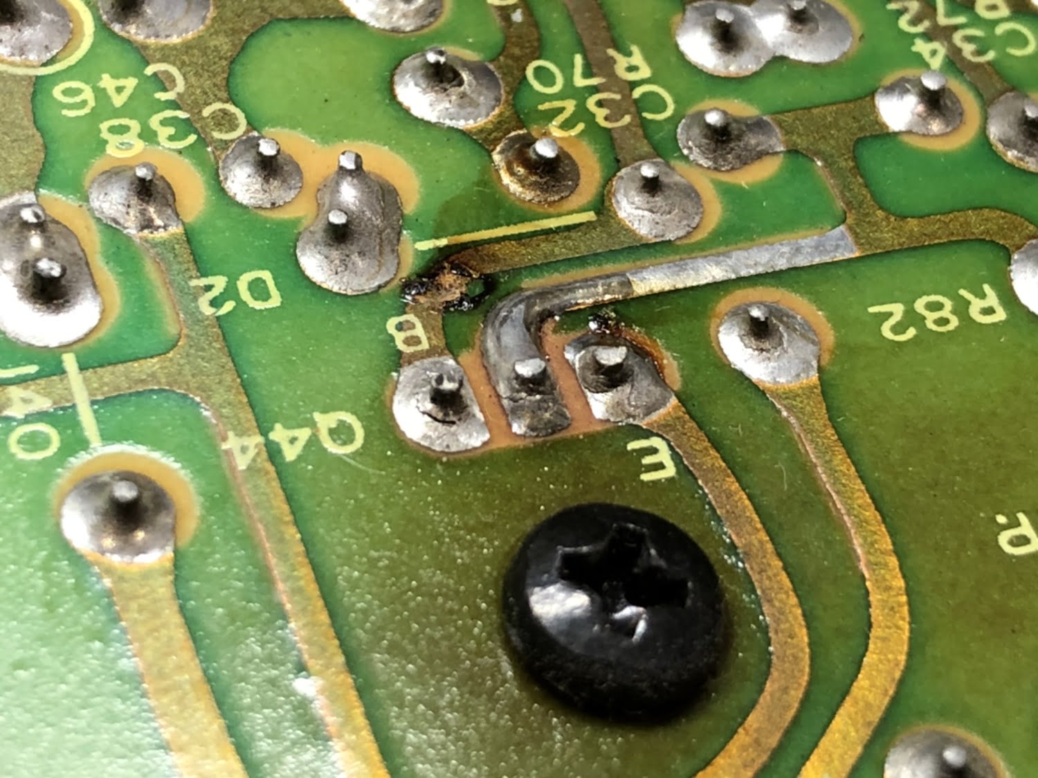
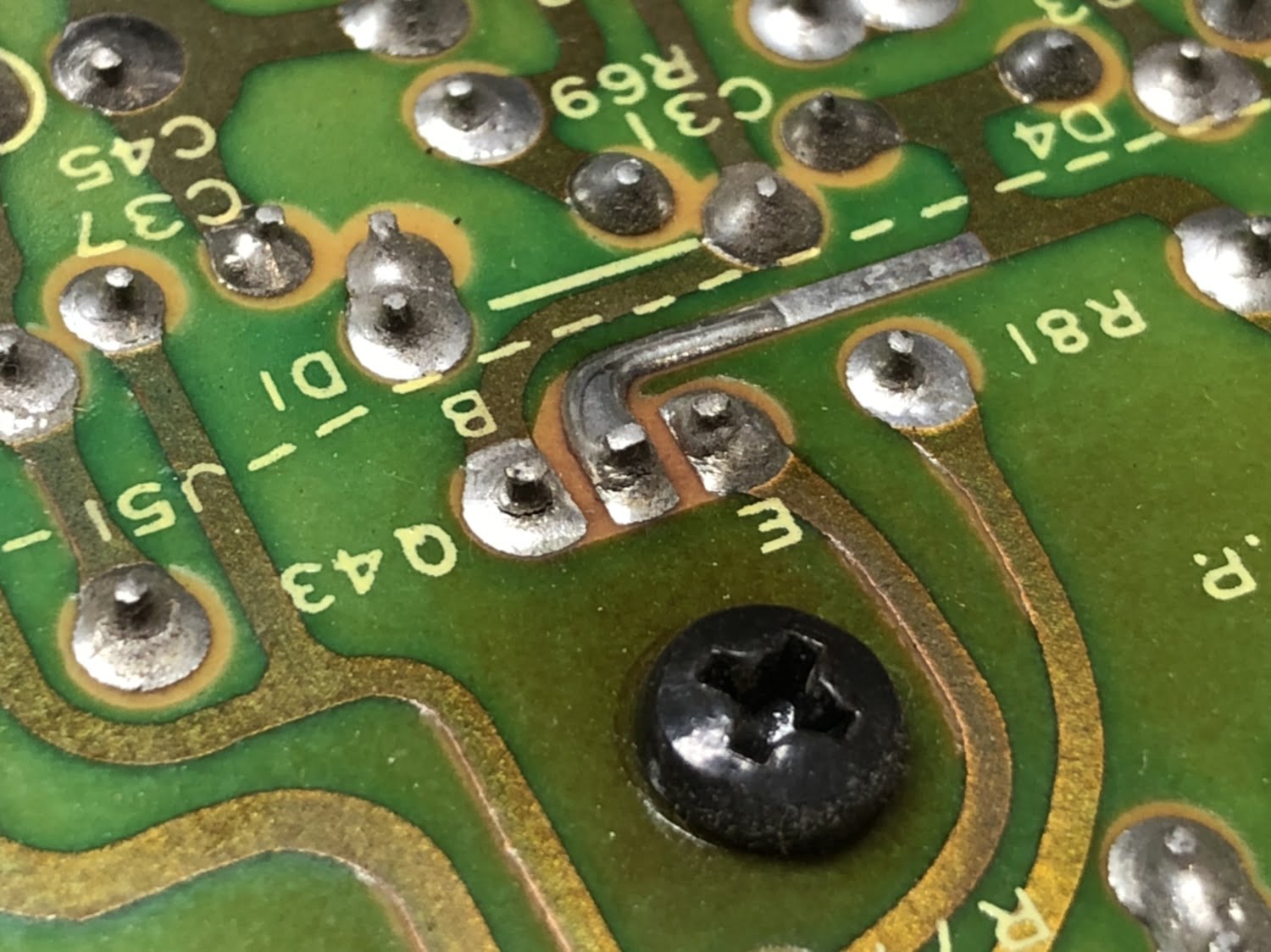
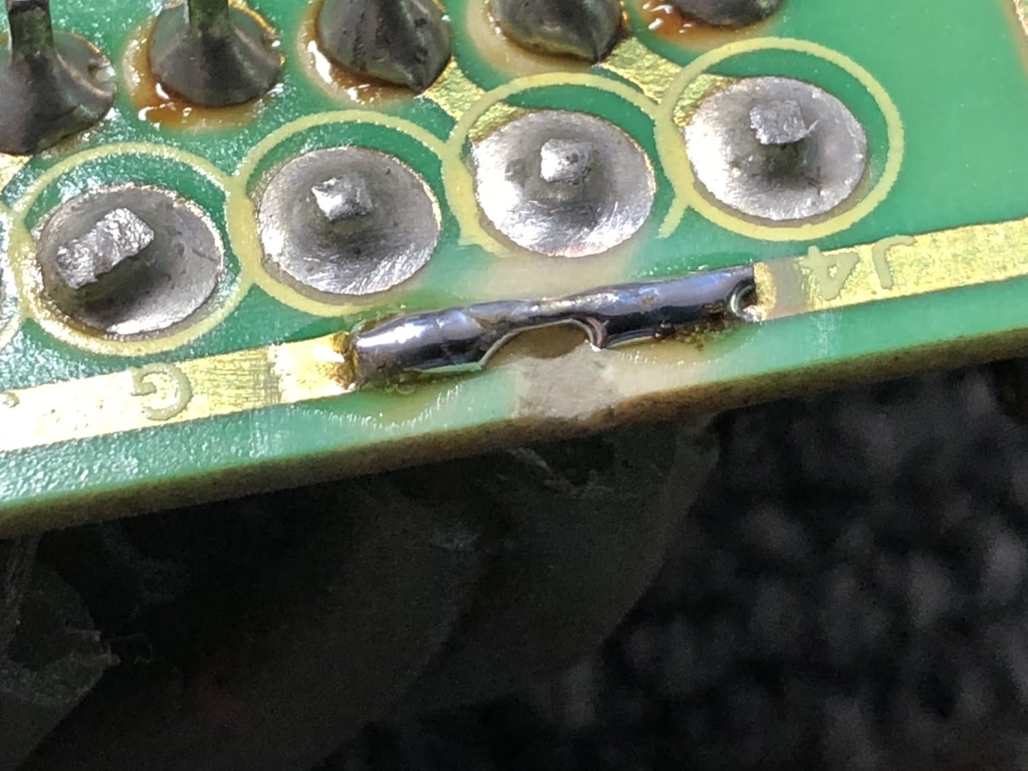
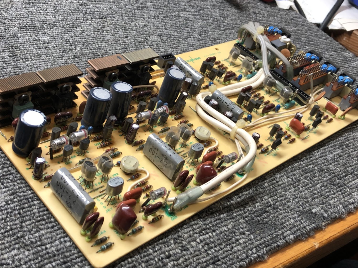
The preamplifier board is a critical one because all signals pass through it unless the amp is operated in power amp bypass mode. The E-303 has an especially nice FET based phono preamp and there were massive DC offsets through this area, so she needed some extensive work. Someone who previously worked on this E-303 had also damaged a trace to the extent that it was almost destroyed.
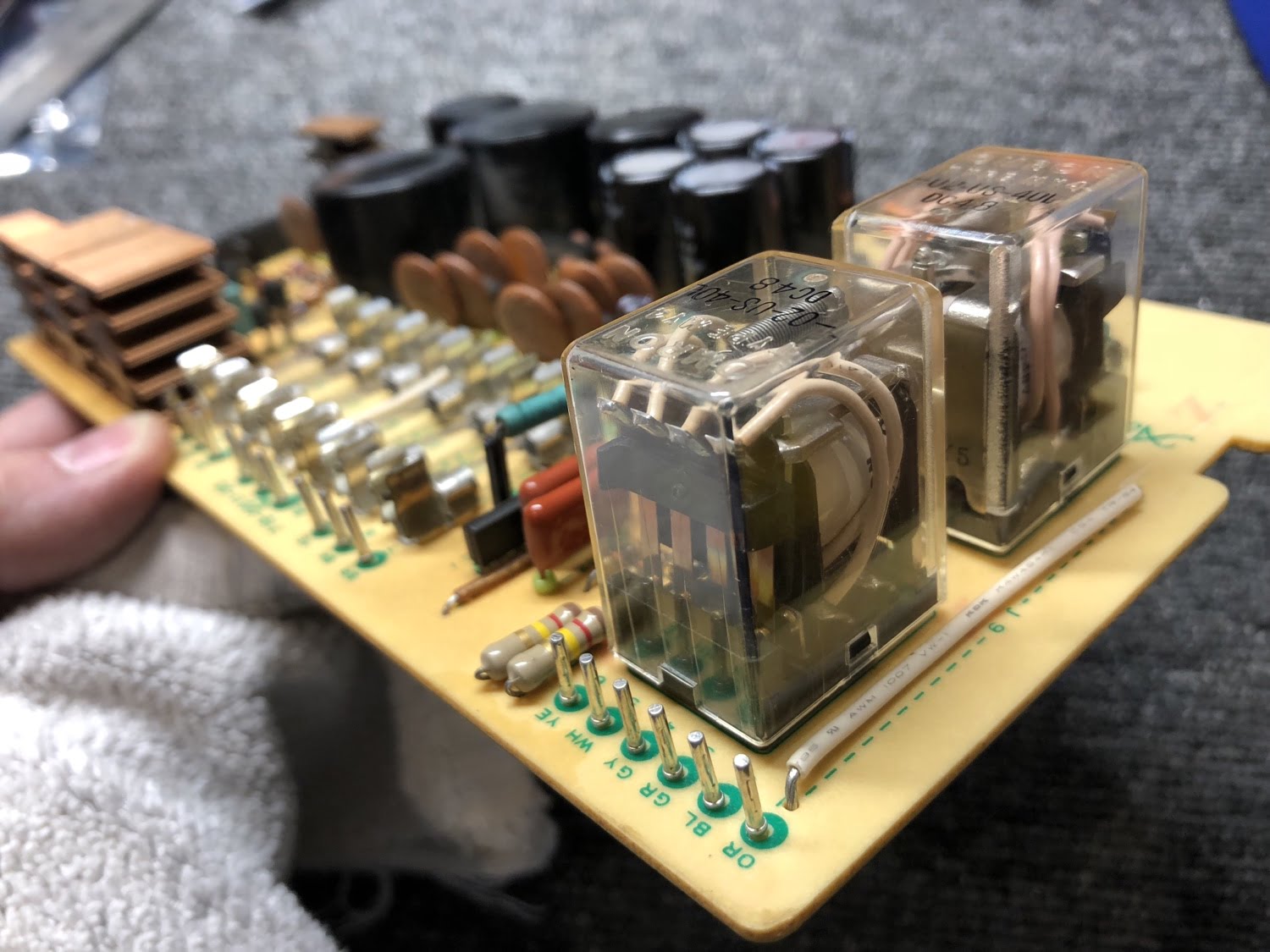
Mute Relay Board
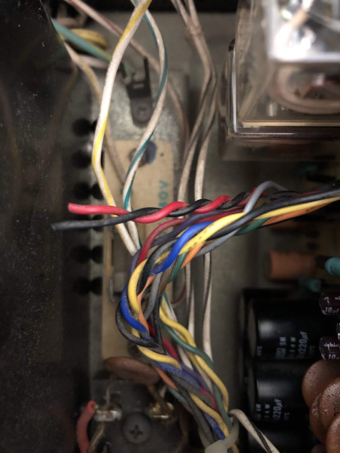
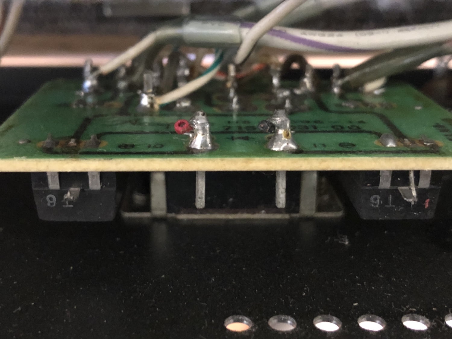
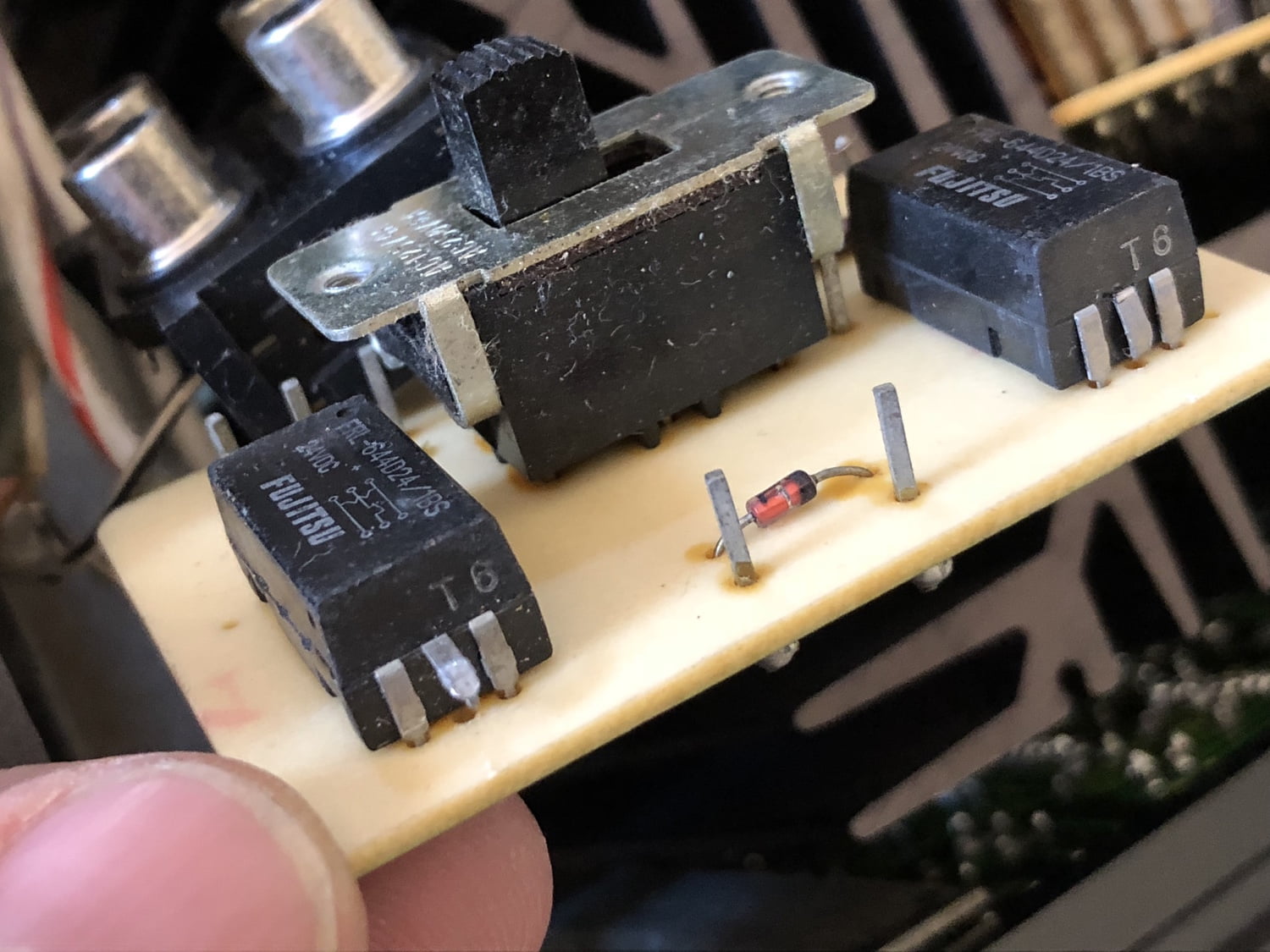
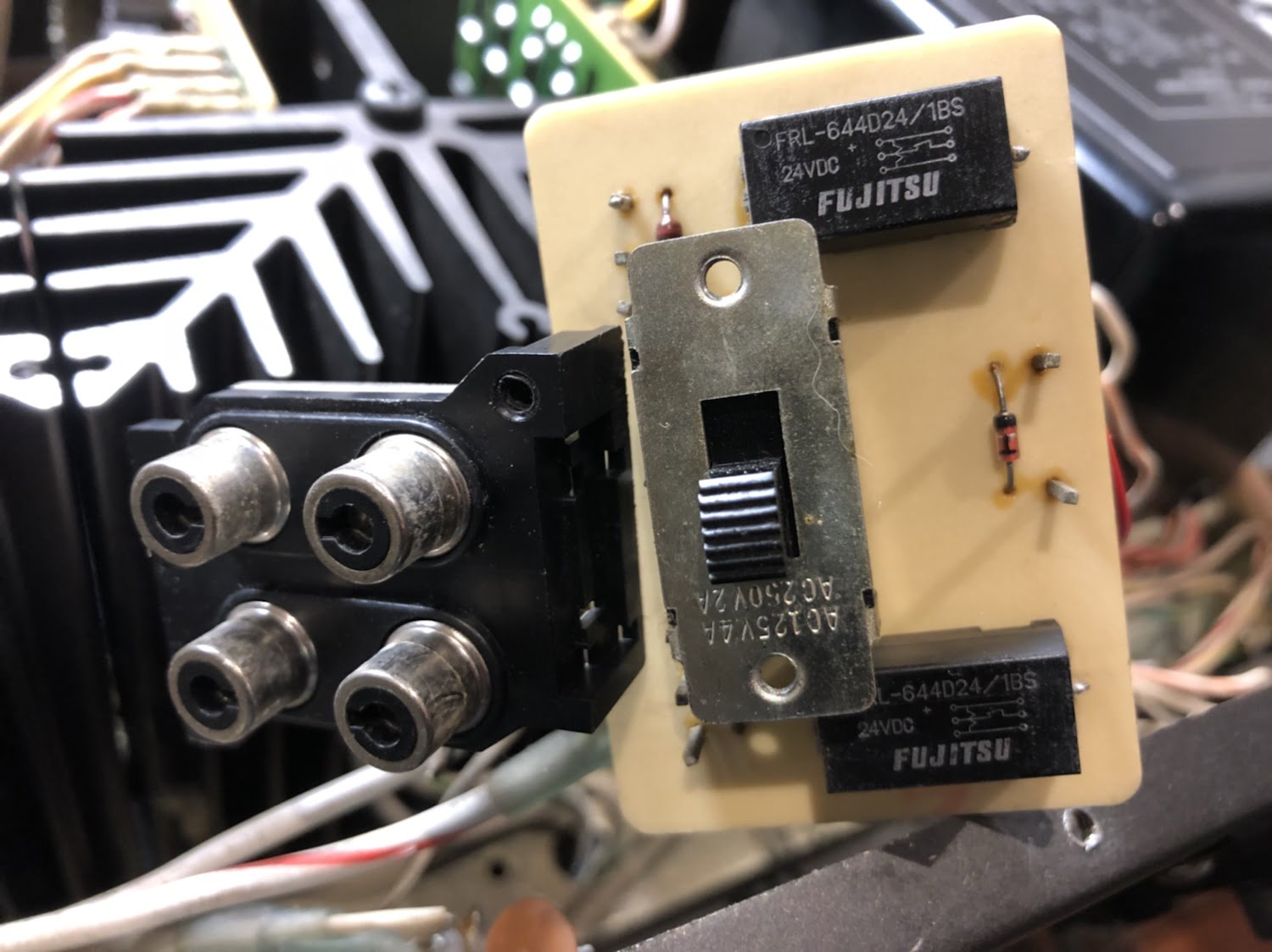
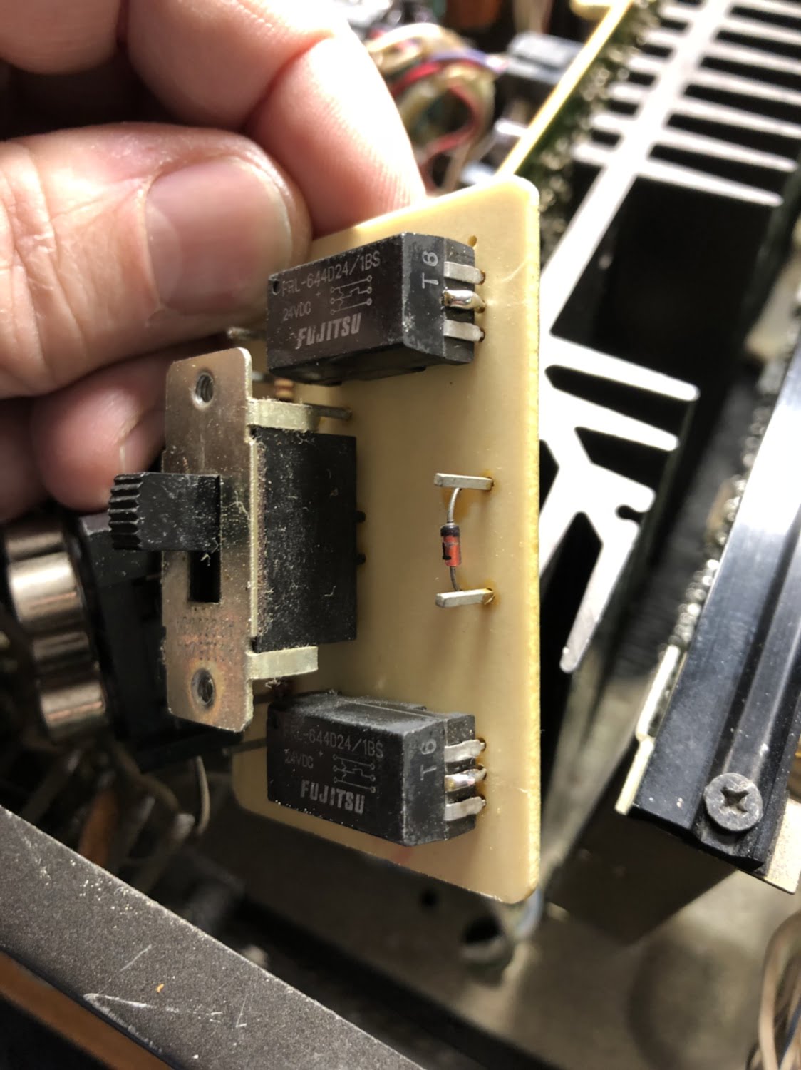
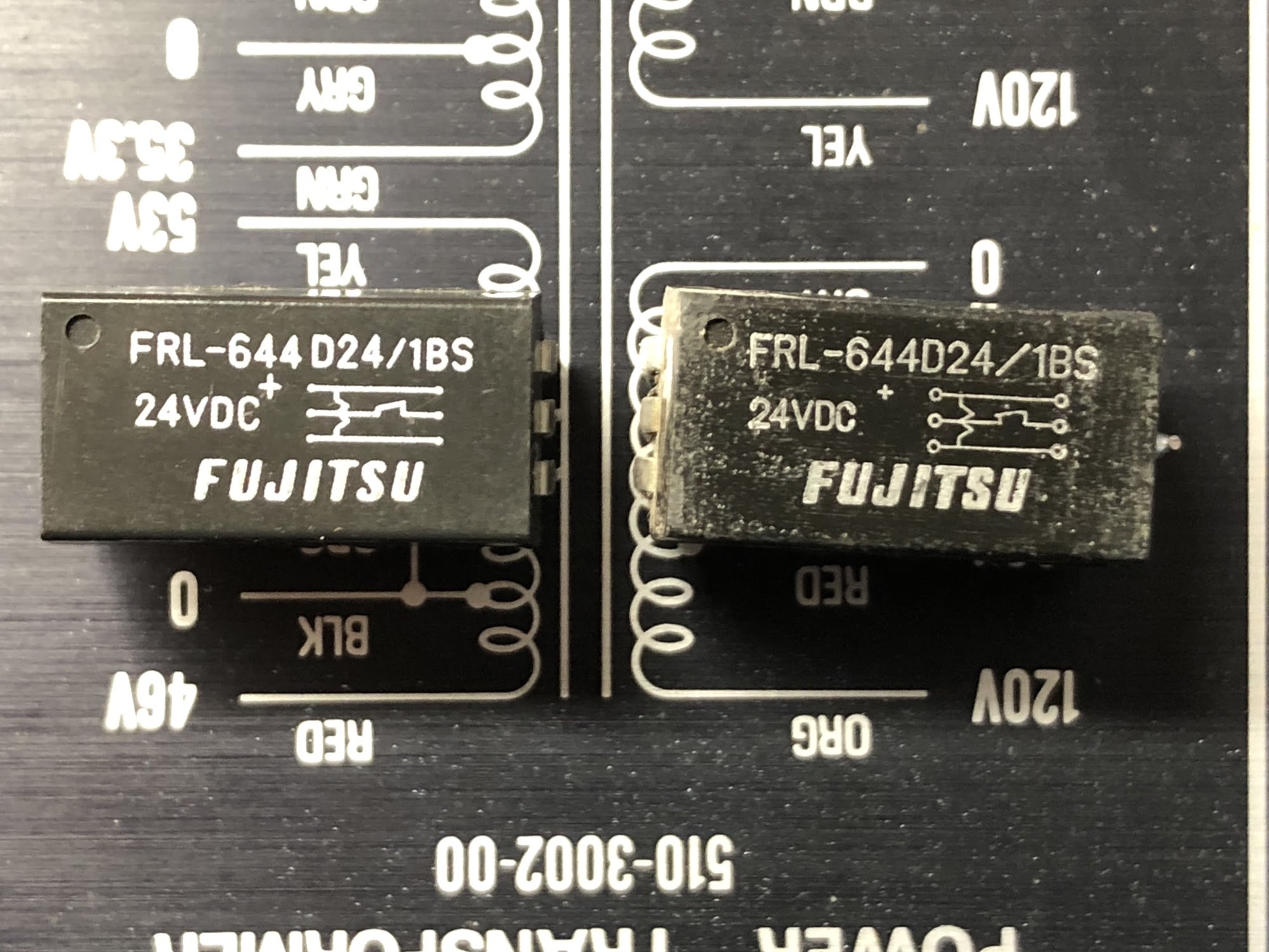
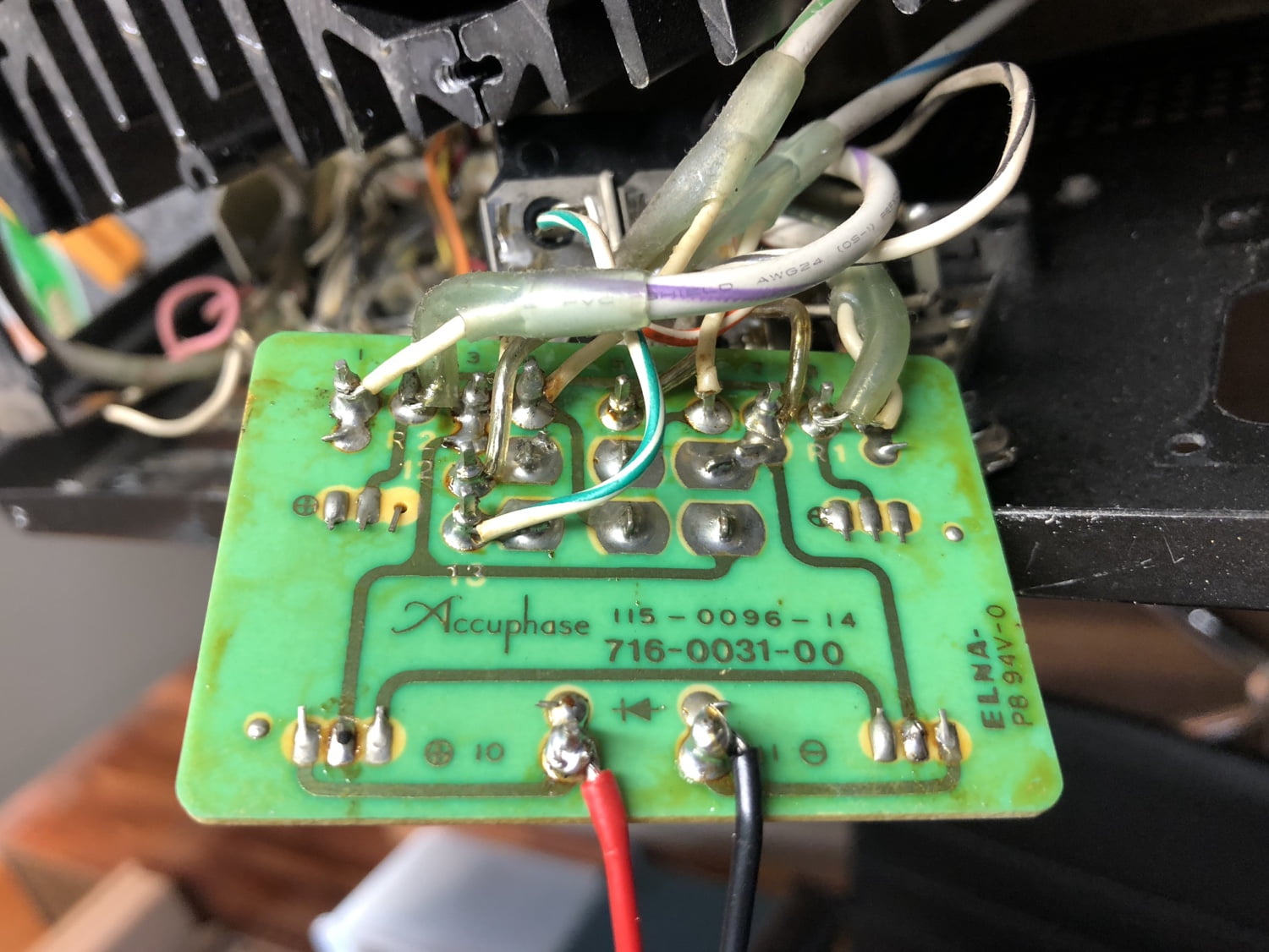
There was one very strange problem that I simply had to resolve for my customer. Someone had attempted to repair a mute relay problem but decided it was too difficult. So, they gave up, cut power to the board and lifted pins on both relays, effectively hobbling the whole board and circuit.
Now, these mute relays are there for a reason. They are partly why Accuphase equipment is so quiet in general operation and the board really needs to be working.
Testing and Adjustment
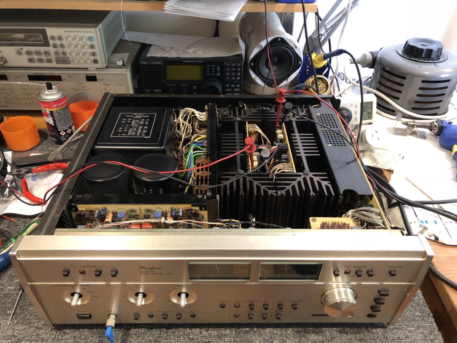
This is the last but one step before cleaning. With the amp on the bench, I run power-on testing, set quiescent current draw and DC symmetry at the various stages of the amplifier. From the service manual, there are 8 separate adjustments in an Accuphase E-303.
Final Cleaning and Results
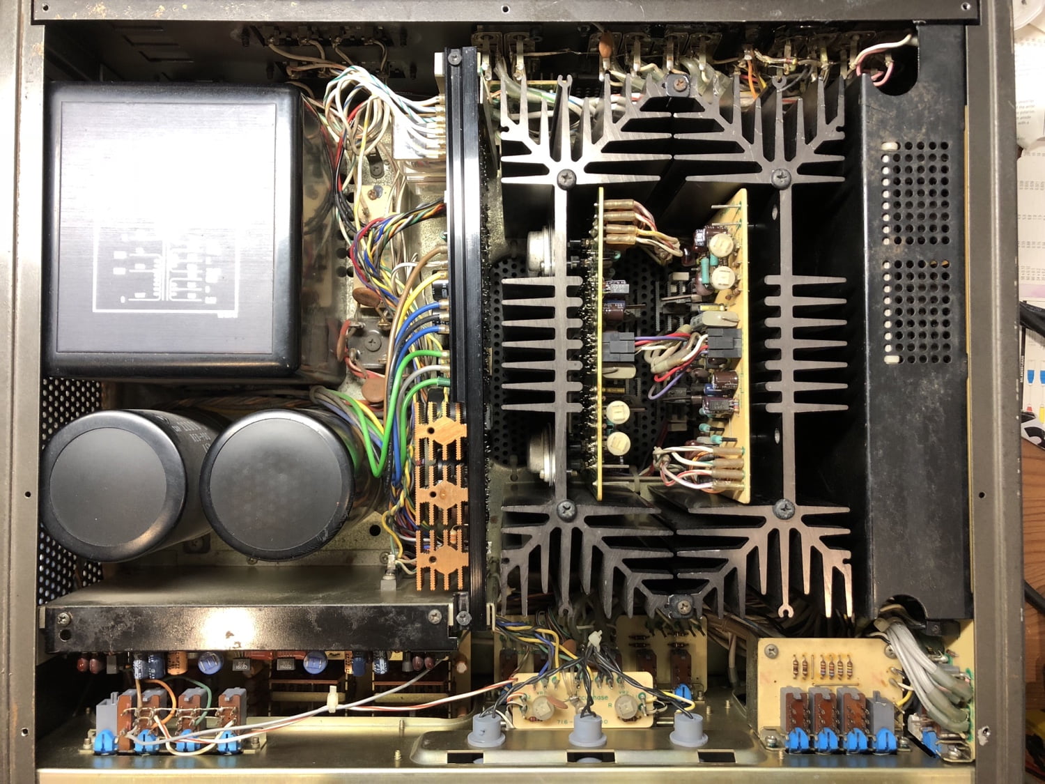
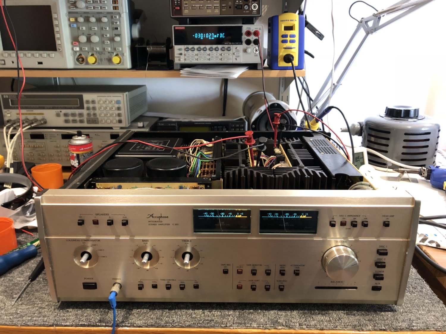
Finally, we come to the end of this epic write-up. The last stages for me are always to clean the chassis exterior, knobs, connectors and so on, followed by a final test and photo-shoot.
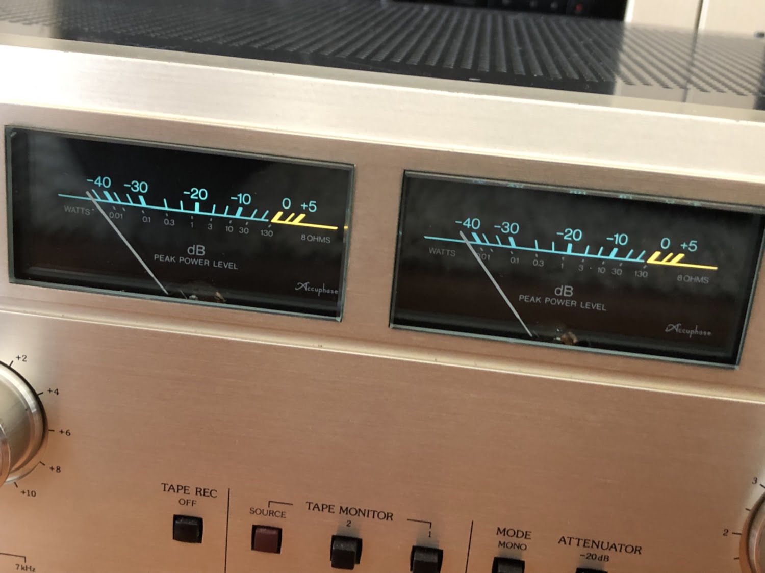
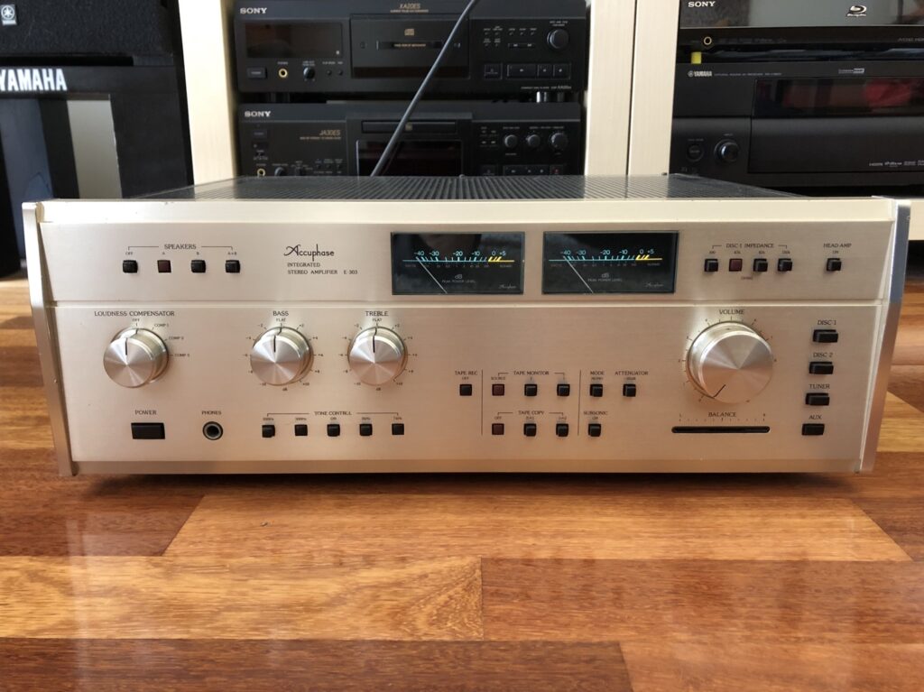
After all the work, this lovely old Accuphase E-303 sounds amazing and runs very well. She’s had somewhat of a hard life and I spent a little more time on one or two of the connectors and switches, but I know her owner is very happy with her. He paid very little for her due to her slightly unloved condition. I think you’ll agree, she looks great now!
It’s business as usual @ Liquid Audio, despite Coronavirus, so if you’d like my assistance with your Accuphase E-303, or any other Accuphase piece, don’t hesitate to get in touch.
Discover more from LiQUiD AUDiO
Subscribe to get the latest posts sent to your email.



Hey Mike I have a fully restored e303 that sounds amazing, it does tend to get quite warm, not hot though, if you put your hand on the top cover. Is this normal? I suppose it’s a hard question to answer but just thought I’d ask.
Hi Ben, these do run quite warm when correctly set up and that part really is critical. You definitely don’t want anything sitting on top of one!
Thankyou for replying Mike. I suppose these run in class A up to a point… certainly sound like it.
Absolutely gorgeous sonics!!!
No problem and actually all conventional amplifiers run in class-A up to a certain point, the E-303 just has a wider class-A envelope than many integrated amplifiers. They sound great even unrestored and can sound even better, depending on precisely what is done, what parts are used and how they are set up.
Hey mike I emailed you just to let you know what the tech said upon completion of the work he did.
Totally understand if you haven’t the time to read it, but if you do then great.
Thanks
Hi Ben, where are you and who was the technician you used here? I haven’t received an email.
Ah just emailed you then!
I am in qld. Unfortunately!!
No problem, I’ve replied via email. It’s hard without seeing the work but most work I see is unfortunately not standard necessary for equipment like this.
Hello Mike,
while chasing the issue of the left channel being quieter than the right (more so the higher the frequency) on my “new” E-303, I stumbled upon your page on the other side of the globe. Most excellent, extremely helpful and a good read on top – thank you for proving such a well of information!
I noticed that on the “712” tone board both your and my amp are missing the C5 cap in an otherwise perfectly parallel layout (C6 is in the other channel). Same on all of the other pictures I could find online. The C5 cap, however, IS shown in the service manual layout an listed in the parts list!
What am I missing here? Any help would be much appreciated.
Thank you!
Markus
Hi Markus, interesting, I’m not sure if you are missing anything there and it’s not something I’ve noticed in the many E-303s I’ve worked on. I’d need one here to take a closer look and don’t have one in the shop at the moment unfortunately. Important to isolate issues like this to a particular functional block, so try to isolate whether it’s the phono pre, the tone/buffer amp or main amp that is introducing this frequency response issue and work from there. It should be relatively straightforward to resolve.
Hello Mike,
after weeks of measuring, de-soldering, more measuring, soldering and hours of tracing signal paths in the schematics (I’m a mechanical engineering with little electronics background who enjoys a challenge but doesn’t have much time) I finally found the error: the previous owner had the – much criticized – loudness section bypassed. Several wires now went directly to the volume knob. One of the wires had come loose causing the described problem.
As to the C5/C6 cap topic, I moved C6 to the C5 position and could not tell a difference. Still baffles me …
Then it took me a couple of weeks to find out why MC phono only worked on one channel. The same person had added capacitors in parallel to the existing ones (C5 and C6; same numbers, different board 😉 and one solder joint now touched the J55 jumper. Apparently the MC input was never tested after the modification 🙁
I bought the amp for EUR 100 and could not be happier after having fixed the beast myself! This amp is incredible! It replaced my modern Marantz PM-8006 and there is no turning back! Also got rid of my ifi phono pre-amp and directly connected my vintage Thorens TD321 with Sony PUA-1600S arm and Denon DL-103R MC cartridge as well as my very-vintage Thorens TD124 with SME3009 arm and AT20SLa MM cartridge. If only there would be a third phono input (and space on my table) for the Kenwood KD-650 that’s stored away in the attic 🙂
Vintage HiFi is so much fun and your reports have become must reads!
Thank you!!!
Great work Markus, job well done in finding the problem and fixing it. The loudness function is actually very useful when listening at low levels as it compensates for changes in hearing sensitivity, restoring a more natural sound at low levels. Many misunderstand its function and utility and it seems the previous owner was one such person! The phono preamp in the E-303 is superb too, it no doubt destroys the iFi and most other affordable phono pres. I’m glad you are enjoying the articles!
Hi, I’m from the Czech Republic and I bought an Accuphase E-303X for $1600. I’m having a problem — when I turn it on, it takes up to an hour before any sound comes out. But once the sound starts, everything works as it should. The relay near the speaker terminals (next to the fuse) clicks like it’s supposed to.
Could the problem be caused by the 35V 100uF capacitor that’s located next to it?
Technicians here don’t really want to fix it unless I pay for a full recap, which would cost around $700. So I’m wondering if I could try to fix it myself — if it’s something simple like that capacitor.
Thanks for your reply!
Hi Igor, thank you for your question and greetings over there in the Czech Republic, I’ve visited, and it is beautiful! I’ve repaired a few E-303Xs over the years, and this is a common problem. Though it eventually comes out of protection, as one would expect of a 40-year-old warm-running amplifier, service and repair are needed at a minimum, with overhaul being highly advisable. Properly caring for an amplifier like this involves much more than replacing a capacitor or two, of course, so I suggest you engage a specialist familiar with the model to do the necessary work. That said, if you feel comfortable attempting this and have the necessary re-work equipment, parts, service manual, etc, then by all means try, focusing on the warmest running parts of the amplifier first. Just have a plan B that includes someone who will look at it if you get stuck.