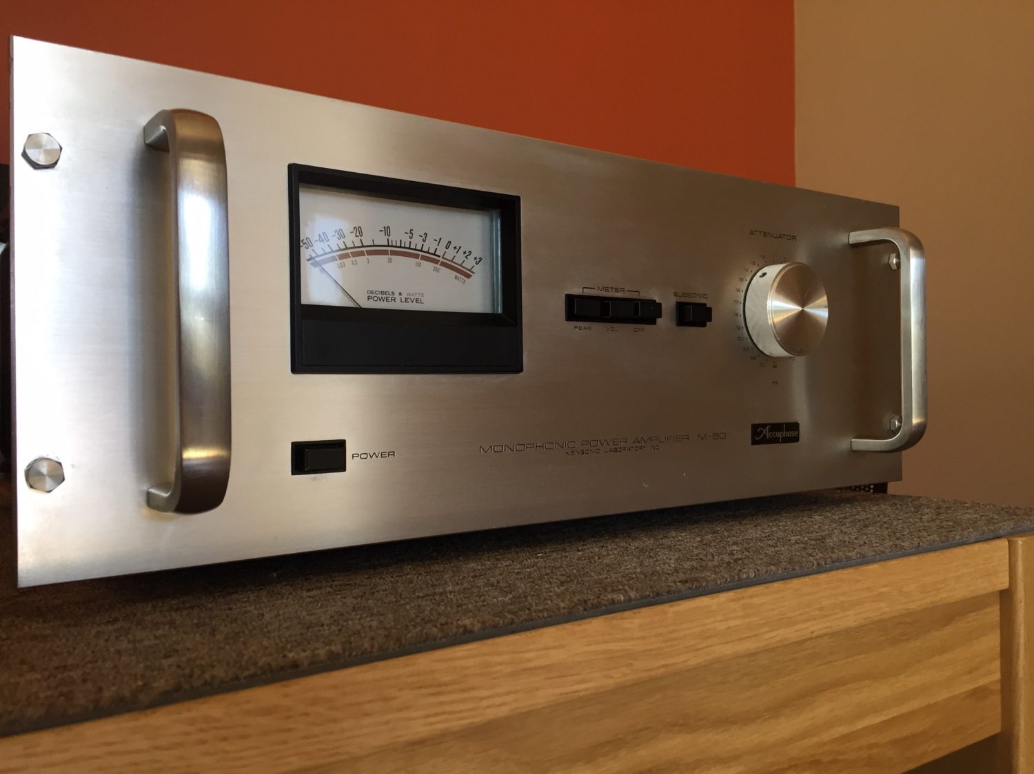
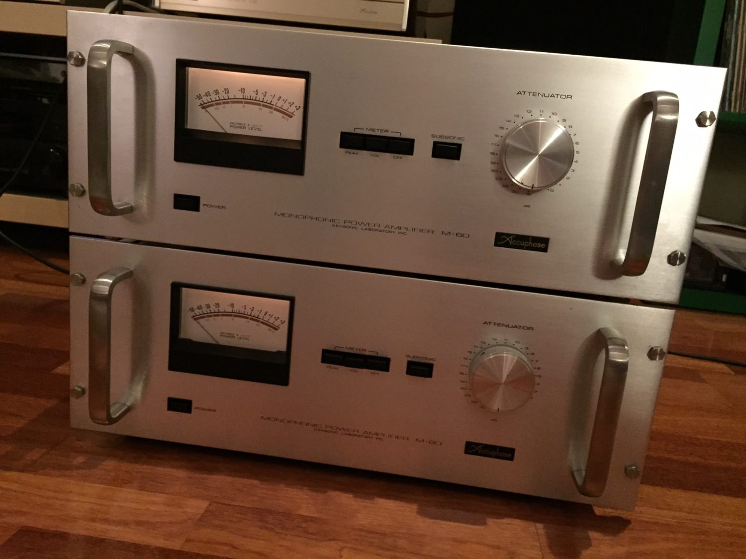
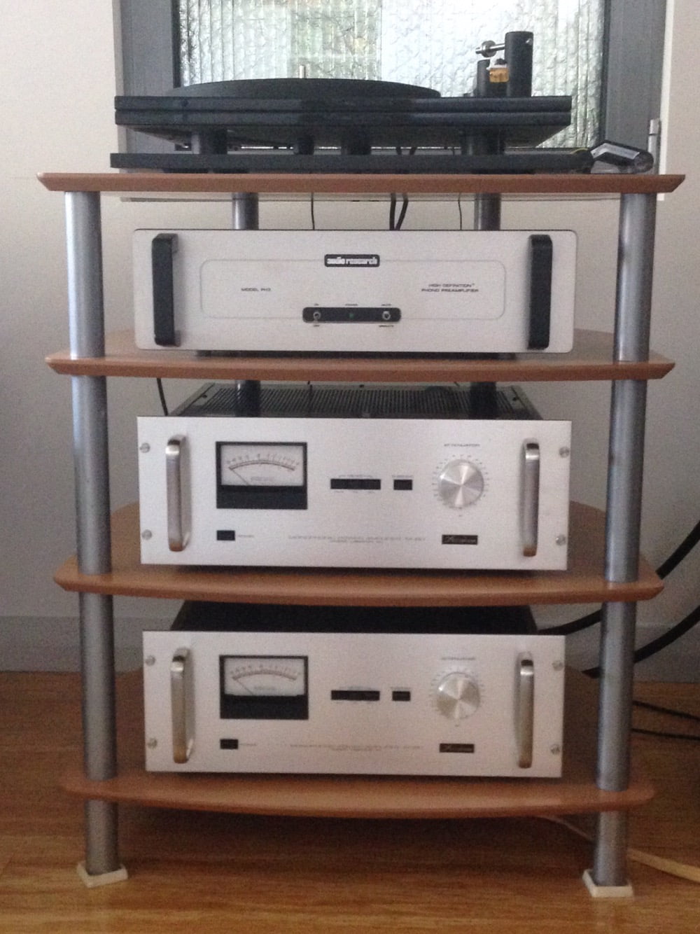
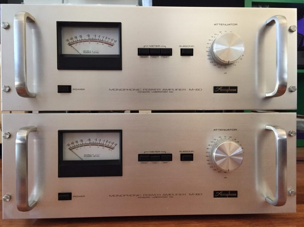
Come with me as we repair and restore two beautiful Accuphase M-60 monophonic power amplifiers and find out how they were ruined by a local repairer.
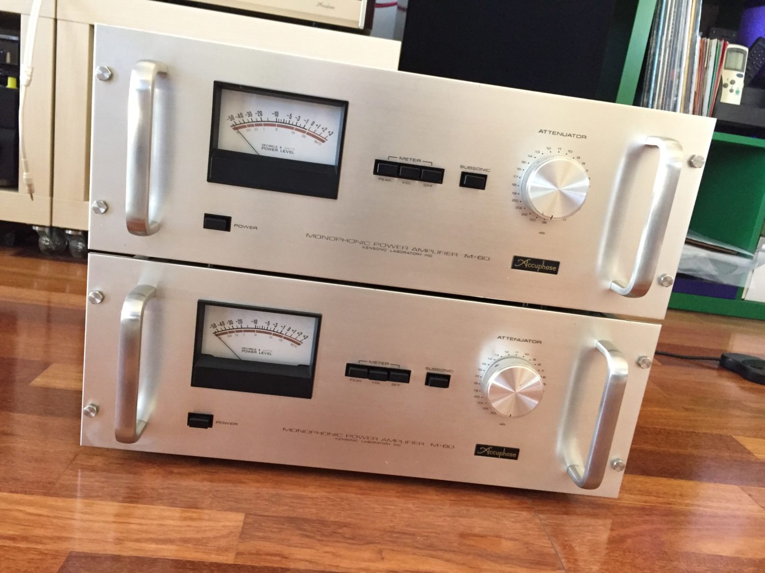
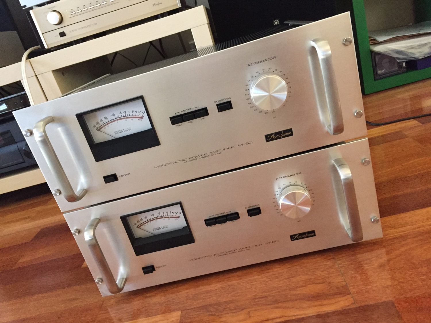
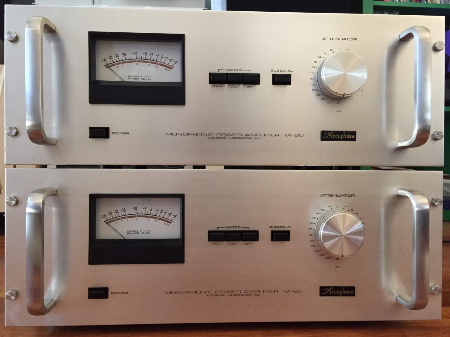
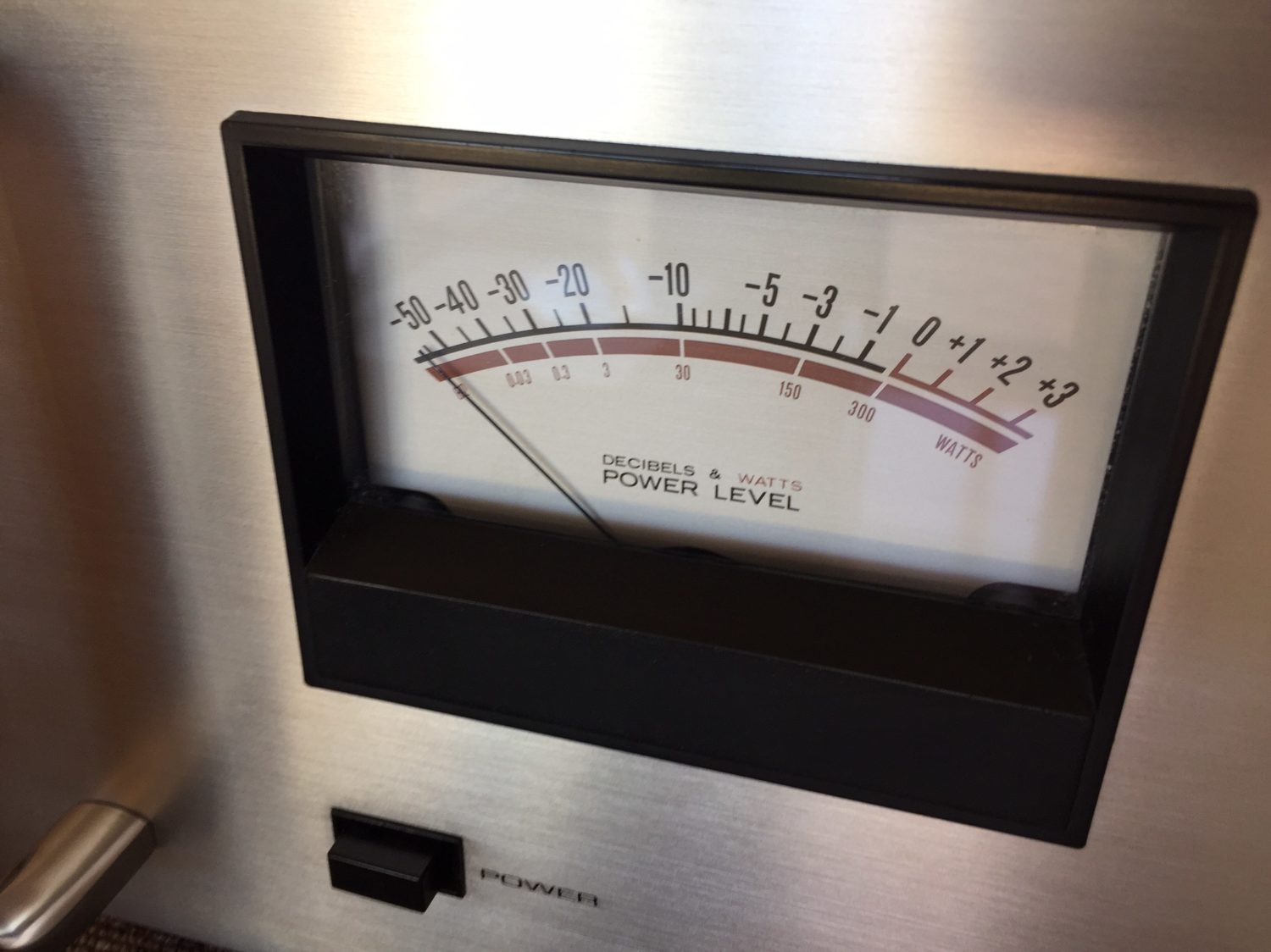
The Accuphase M-60 is a big, heavy monophonic power amplifier. It was top of the Accuphase range when introduced in 1975 and capable of driving almost anything. This beast can output 300 Watts continuously into 8 ohms, more into lower impedances. Given that it’s monophonic, you’ll need two for a stereo setup. There are very few loudspeakers that these amps won’t instantly submit!
If you’d like to find out a little more about the amazing Accuphase M-60, try this link. Hi-Fi Engine has more here, and Accuphase’s own material on the M-60 is located in their wonderful Product Museum.
Accuphase M-60 Specifications
| Form | Monophonic power amplifier |
| Output power (20Hz – 20kHz, 0.03% distortion) | 450W (4 Ohms) 300W (8 Ohms) 150W (16 Ohms) |
| THD (20Hz – 20kHz) | 0.03% or less (at max power) 0.01% or less (at -3dB output) 0.05% or less (at 50mW output) |
| IM distortion | 0.01% or less (at Output power) |
| Frequency response | 20Hz-20kHz, +0 / -0.2dB (at max power) 2Hz-150kHz, +0 / -3.0dB (at 1W output) |
| Damping factor (8 Ohm load) | 120(40Hz) |
| Input sensitivity/impedance | 2.0V/100 kOhm |
| S/N ratio (IHF-A) | 115dB (at Output power) |
| Subsonic Filter | 17Hz, 18 dB/oct |
| Power output meter | Logarithm compression type |
| The semiconductor used | Transistor: 47 pieces IC: Three pieces Diode: 51 pieces |
| Power supply voltage | 100V/117V/220V/240V, 50Hz/60Hz |
| Power consumption | At idle: 65W Into 4 Ohms, max output power: 800W Into an 8 Ohms, max output power: 540W |
| Dimensions | Width 482 x height 170 x depth 345mm |
| Weight | 27kg |
| Option | Accessories (with fan) O-81 (8,000yen) |
A Sad Tale of ‘Recapping’
My customer purchased this pair of Accuphase M-60 power amplifiers and enjoyed them for a while, before deciding to have them ‘refreshed’. This approach is very sensible and spending money on a superb pair of amplifiers like this is a no-brainer.
Simon chose a local, Fremantle-based repairer who specialises in guitar amplifiers and other musical instrument type gear. Unfortunately, though I’m sure this gentleman means well, experience has shown that he ends up causing more problems than he solves and sadly that proved to be the case here, as my customer was to discover.
UPDATE: the repairer in question has closed down, as of late 2020.
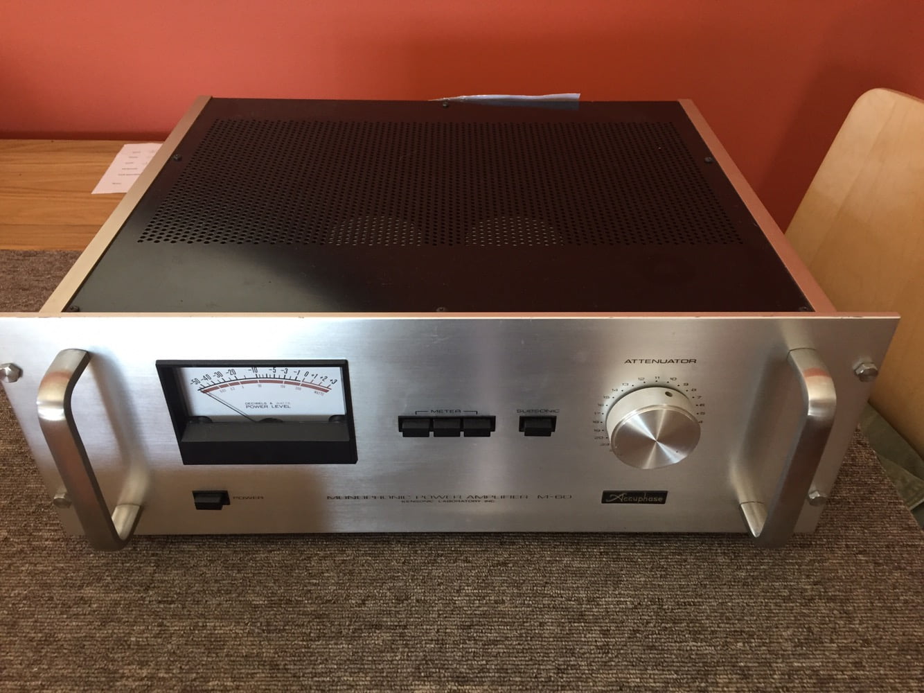
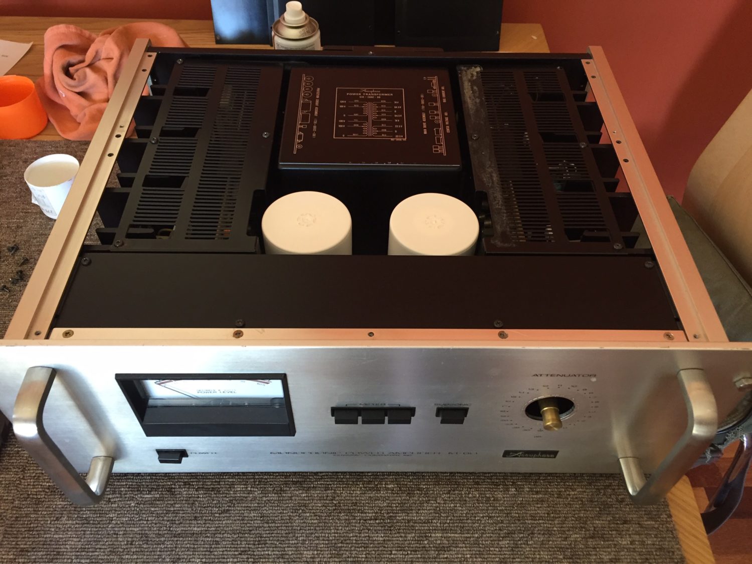
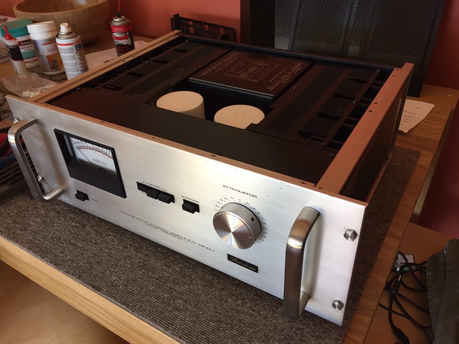
When I first inspected this Accuphase M-60 amplifier pair, it solidified my view that this repairer should not be working on hi-fi gear. I knew this because I’ve repaired other stuff that he’s worked on and this guy should have stuck to guitar amps as he is incapable of executing the technical work necessary on complex equipment like the Accuphase M-60. Sorry, but that’s the truth.
Anyway, the repairer decided both amplifiers needed a ‘recap’. Recapping is all the rage and many seem to think it will magically fix any problem which is of course far from reality. An amplifier or anything else must be assessed from a technically informed perspective and each piece given the attention it needs. Whilst recapping is in vogue, the average person doesn’t have the technical knowledge, equipment or experience needed to determine if recapping is required, let alone how to do it correctly. There is also a lot more to consider beyond the state of the capacitors.
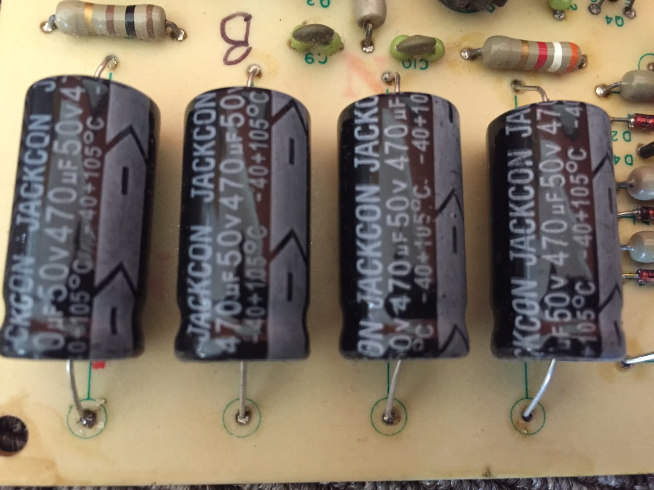
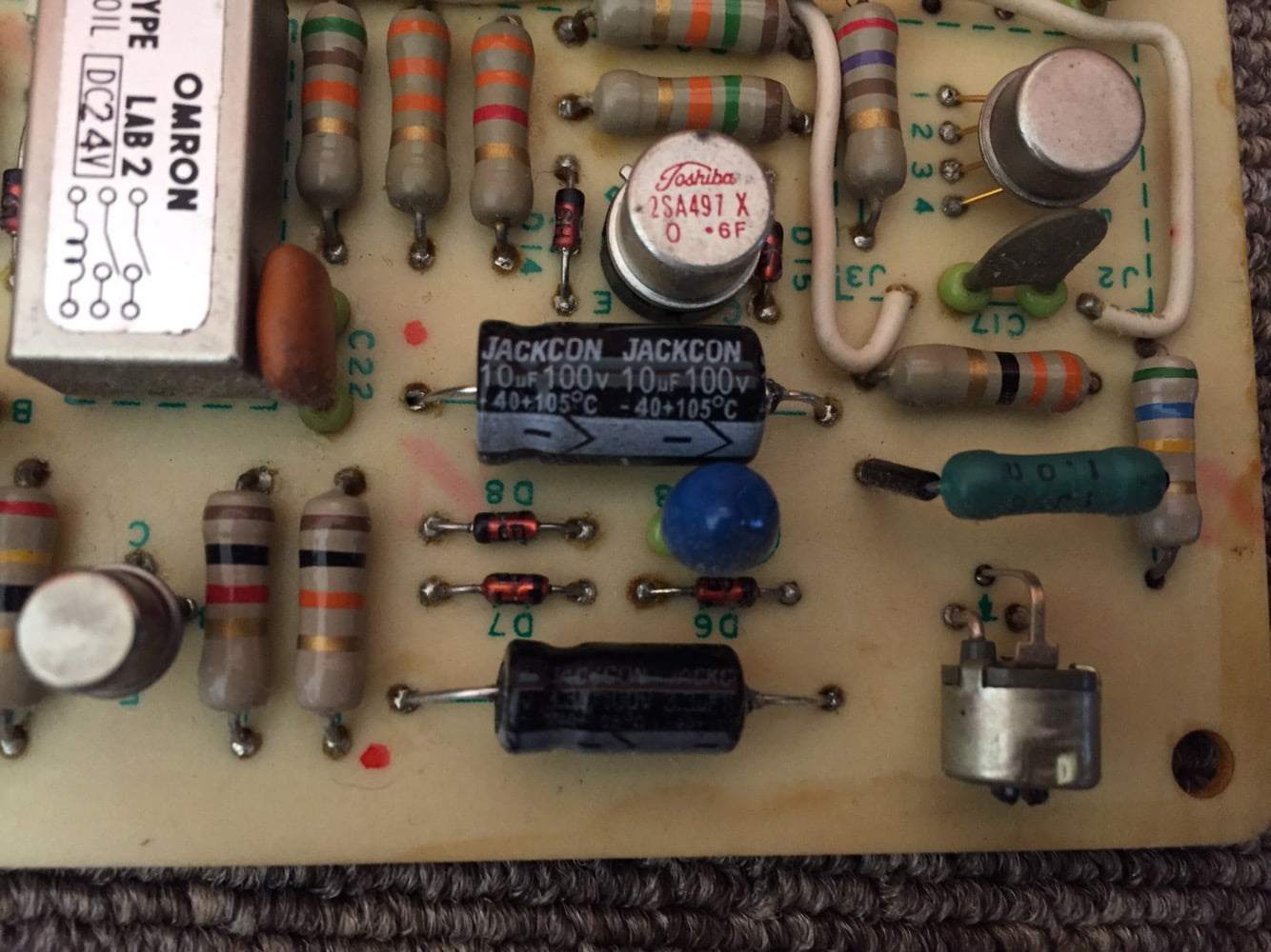
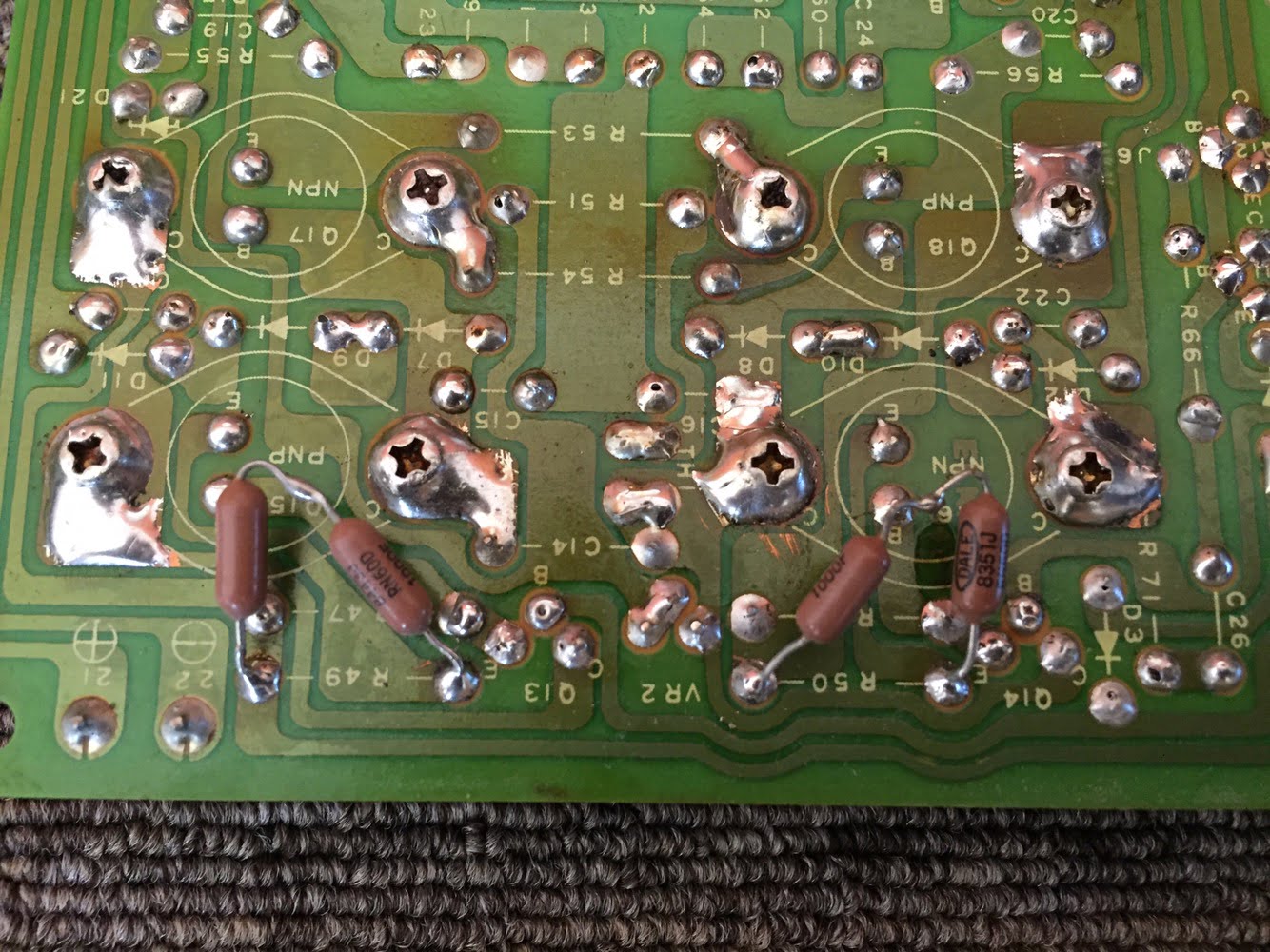
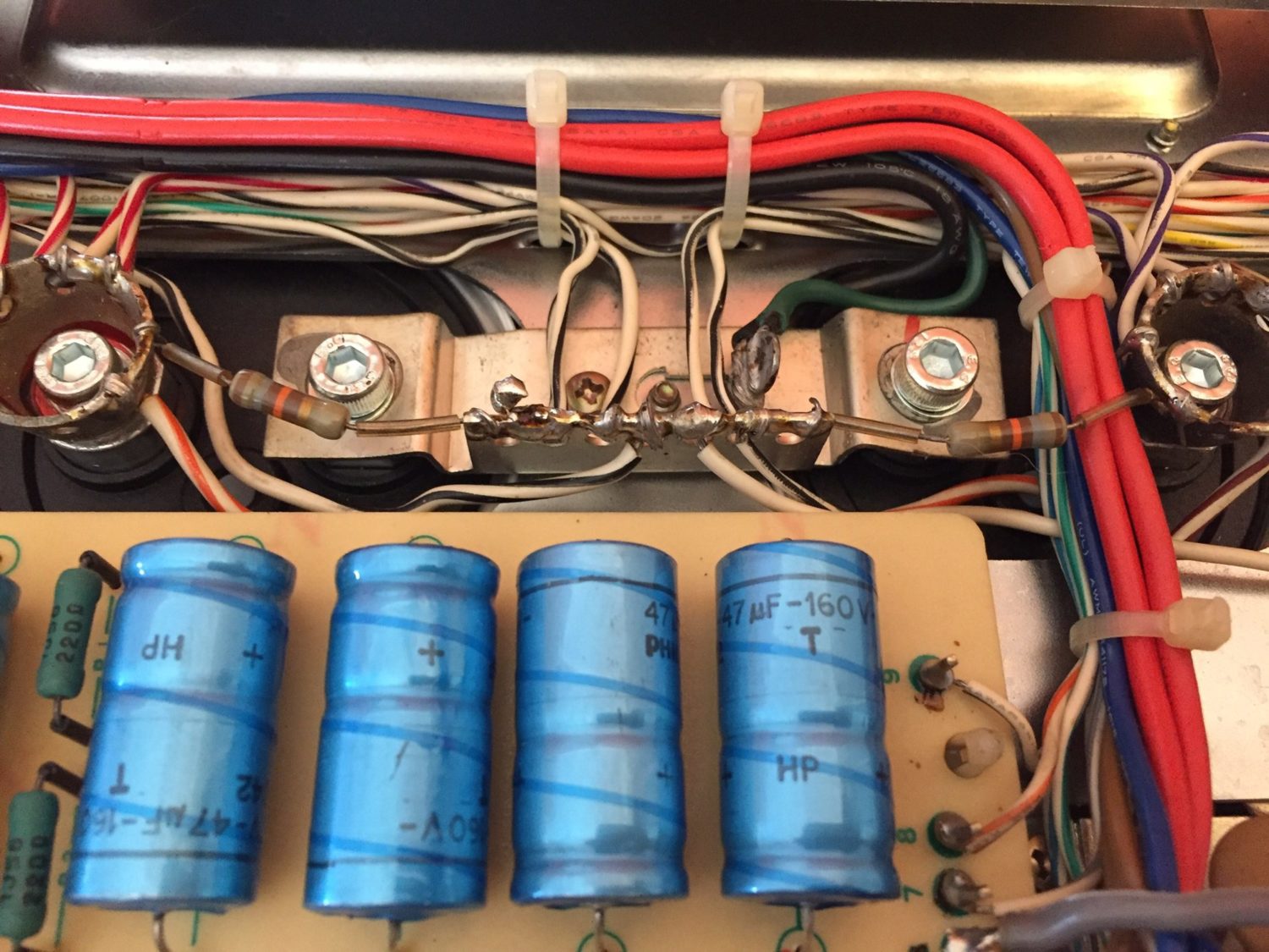
In this case, the guy removed all the vintage, high-quality and electrically perfect Elna capacitors and replaced them with – you guessed it – Jack’con’ and Samxon capacitors! I’m not kidding. He ripped out premium, vintage Japanese parts that have a large bearing on the way Accuphase gear sounds and replaced them with literally the lowest quality parts you can buy. If he’d simply tested them, he’d have found that the capacitors he removed were electrically perfect. I know this because my customer kept all the original parts and I tested them before re-installing some of them.
Recapping Rules
Trying to fathom the thinking here isn’t easy. Imagine you own a car with four premium tyres with lots of life left on them. You take it in for a service. When you get the car back, you discover they removed these good, expensive tyres and replaced them with cheap new Chinese ones. Would you be happy? Probably not.
At this point I know what you’re thinking: “Mike – how do you know the original capacitors were good?” Good question. My customer was smart enough to ask for all the removed parts and he kept them. He brought them to me when I repaired his amplifiers. I tested them, all were perfect.
I’m often asked about my thoughts on recapping and if I have any ‘rules’ about this topic. The reality is that there is no rule regarding recapping older gear. Each piece should be assessed on its merits. One must consider the condition, type of equipment and type of caps. You need experience and the correct test and measurement gear to make these assessments. If you think that all caps older than five years of age should be replaced, for example, you are quite wrong. I regularly work on gear with 50-year-old electrolytic capacitors that measure perfectly.
Accuphase gear rarely needs complete recapping because of good thermal design and high-quality original factory parts. I selectively replace caps in equipment like these Accuphase M-60 amplifiers, based on testing and on what I know from experience should be replaced. Testing avoids guesswork and there is no place for guesswork in this type of work.
Output Device Madness
Simon’s amps ran for a few weeks after their original restoration, then one of them blew up. Big puff of smoke, apparently, would have been frightening. Then the other one blew up. This repairer charged my customer $3000 to ruin his amplifiers. It’s sad, but I hear stories like this quite often. Simon found me and asked if I could help.
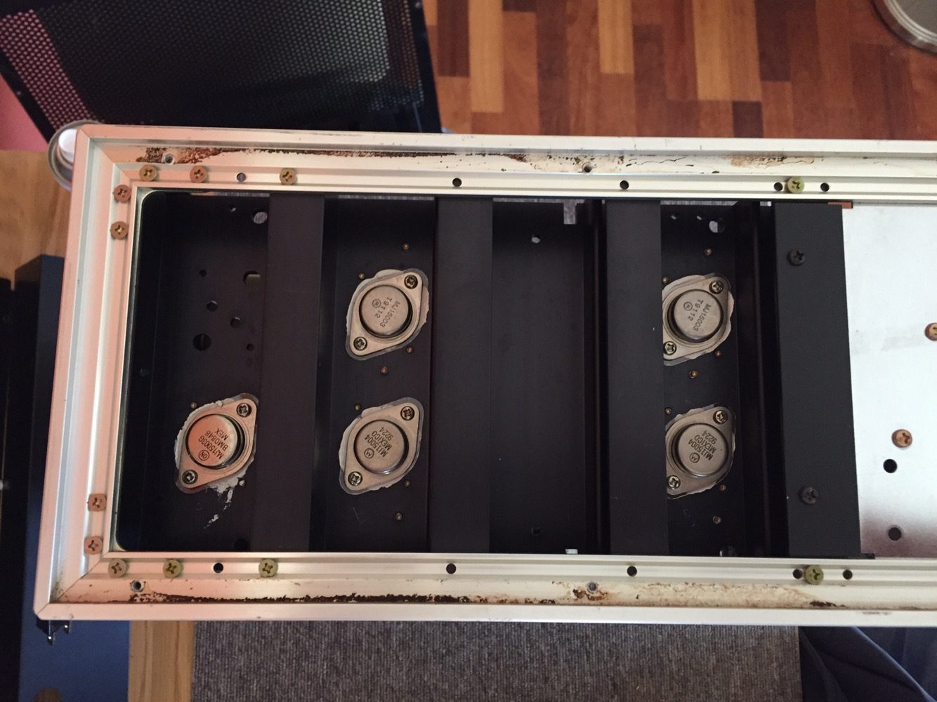
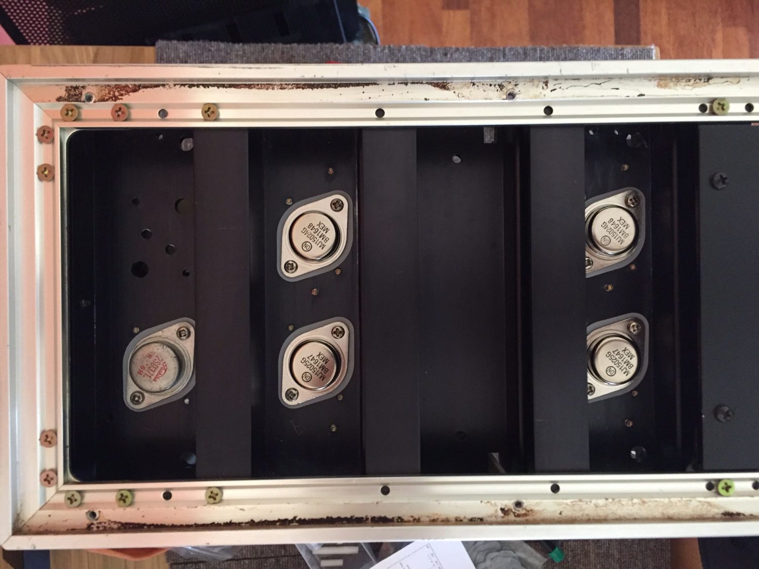
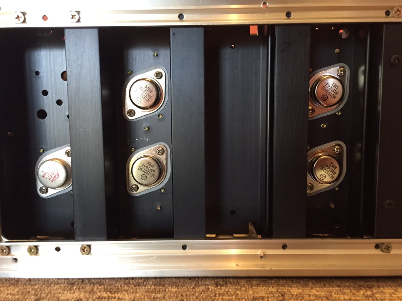
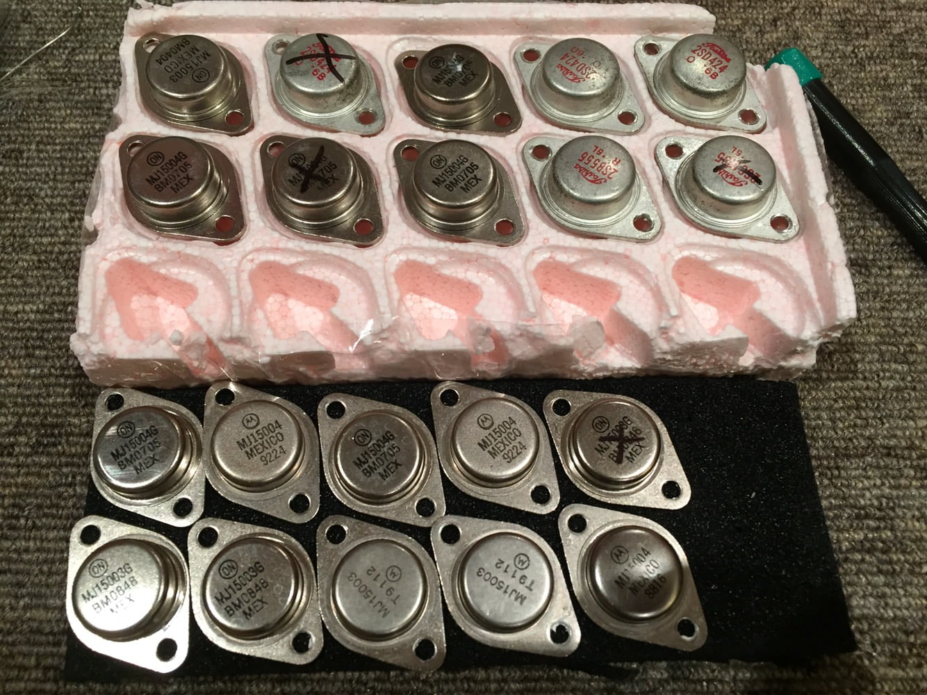
I love restoring audio equipment like this and I could see why these amps had died. No two output devices matched, all were from different batches, different years, different manufacturers. They weren’t even in complementary pairs, essential for stable operation. I’m not kidding, this is the worst case of transistor mismatching I’ve ever seen.
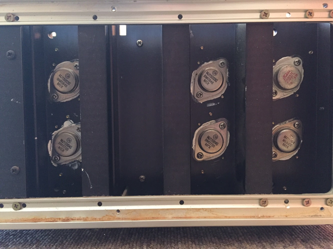
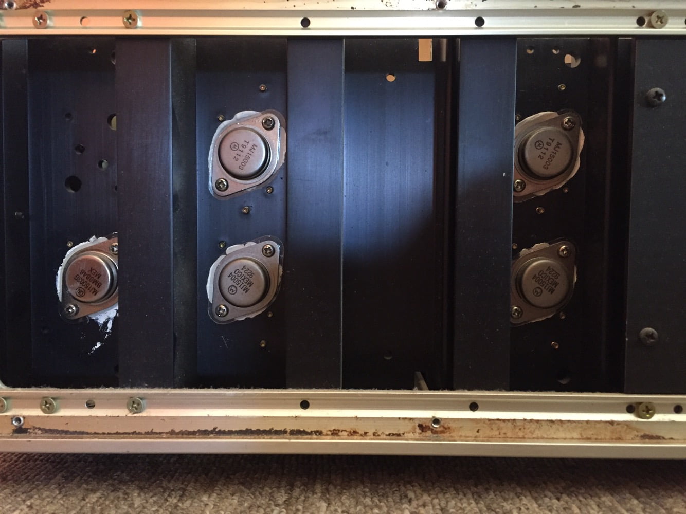
I don’t know for certain who installed all these mismatched devices, and how many looked at this and thought it was OK to leave them in place. I do know that no competent technician would knowingly install a range of incorrect, mismatched output devices from different years, or leave them in place, as you see in these Accuphase M-60 monoblocks. Yet here they are.
Cleaning
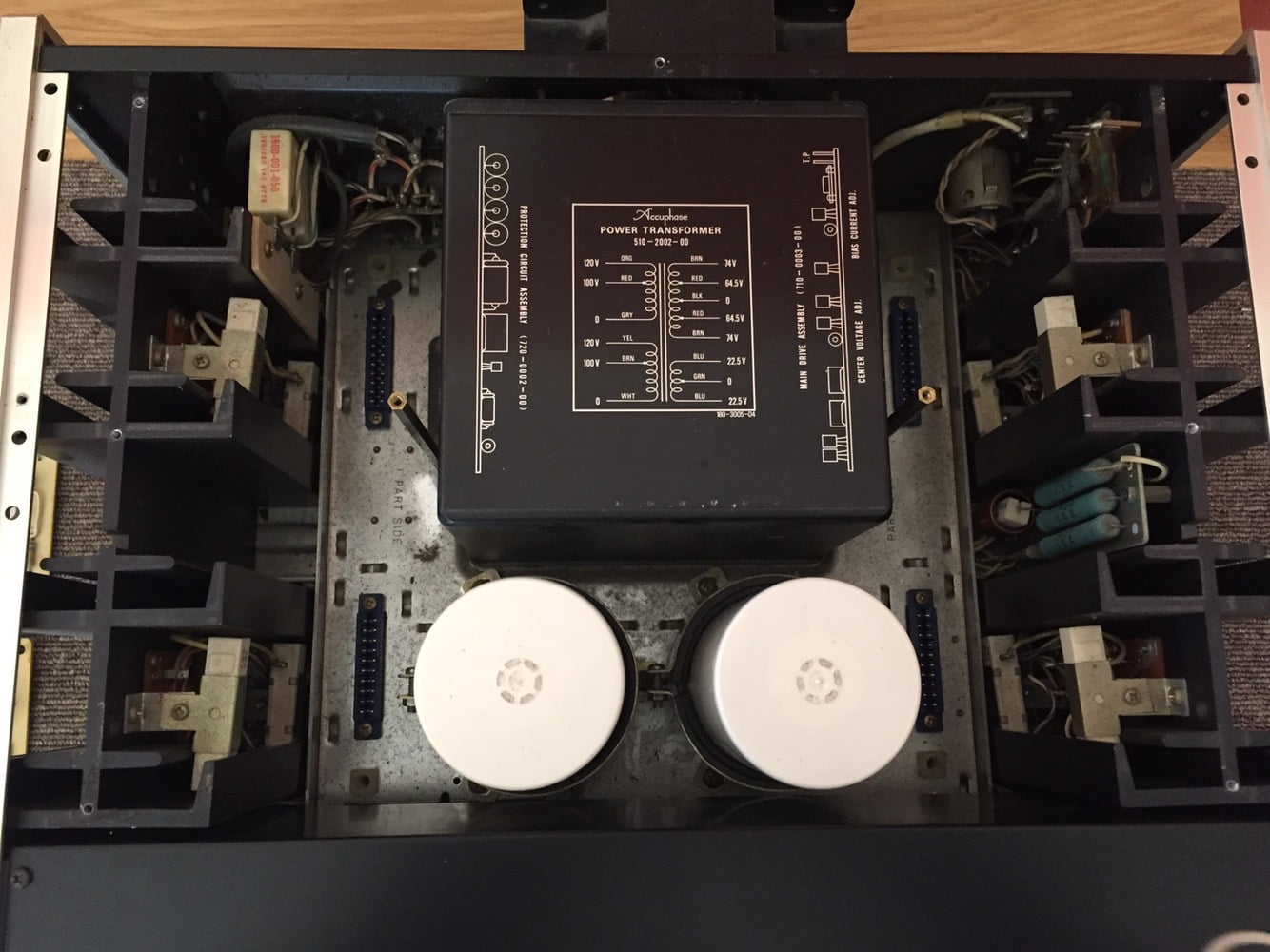
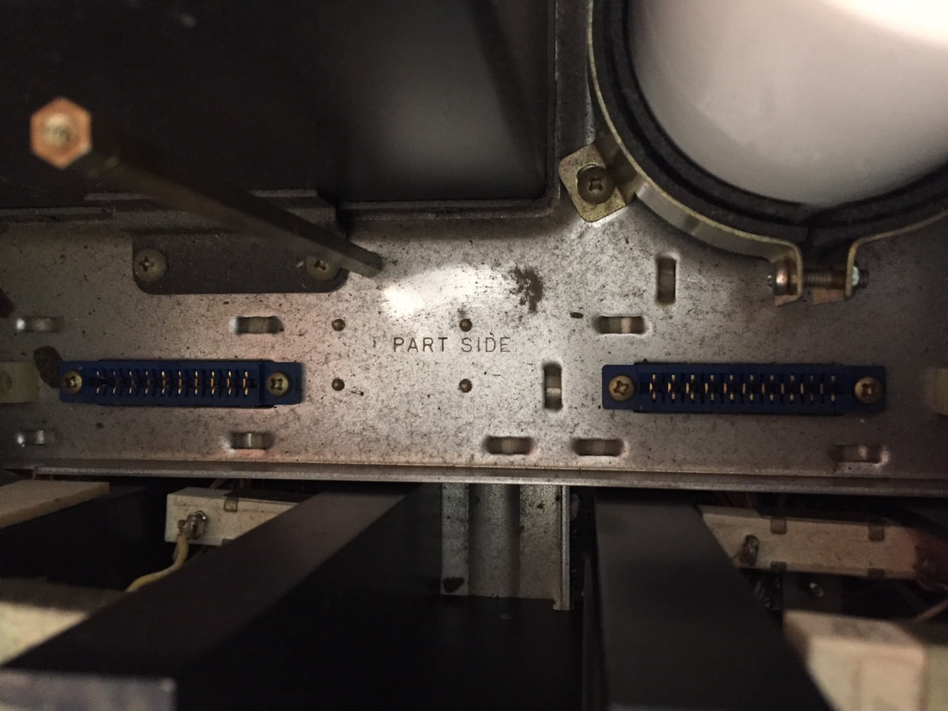
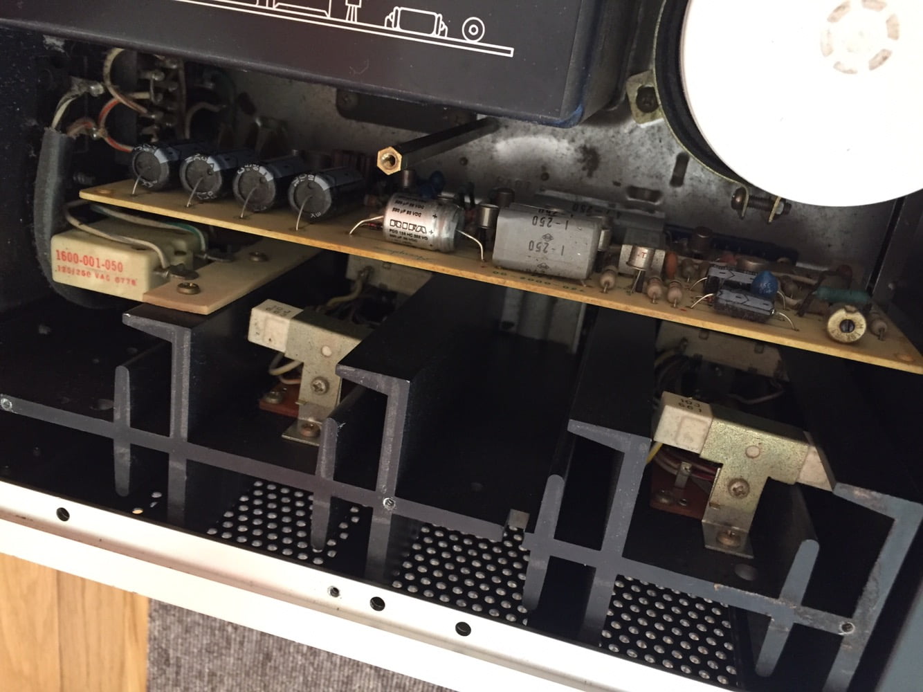
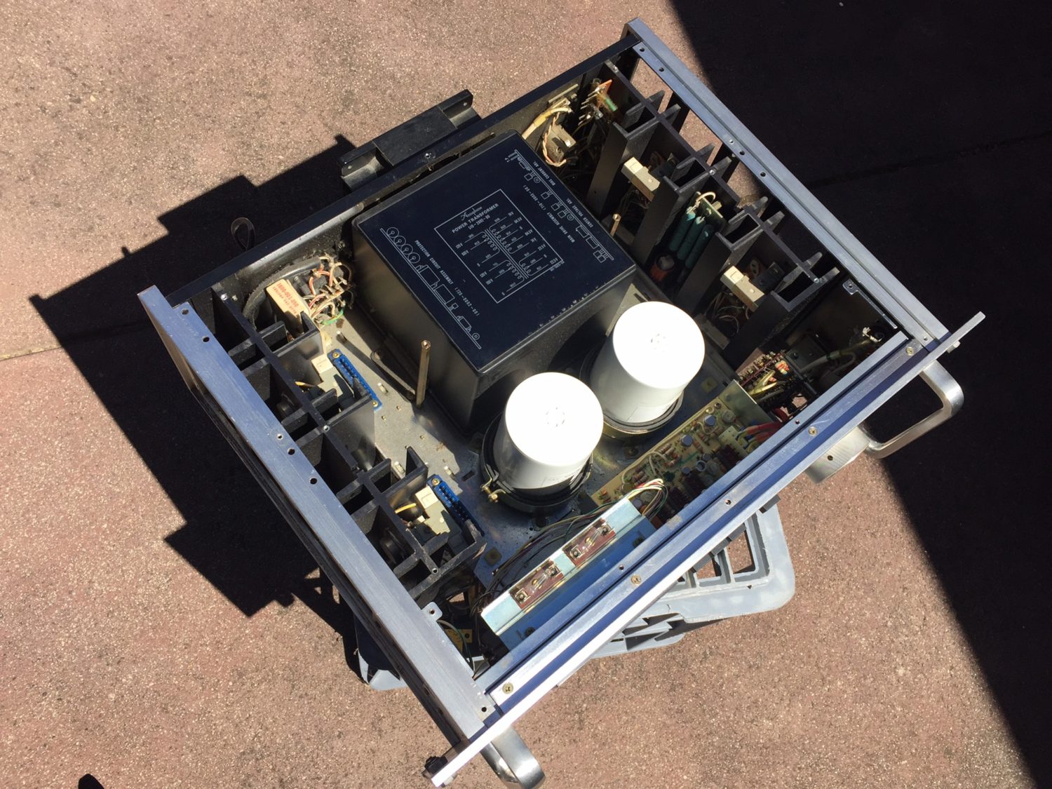
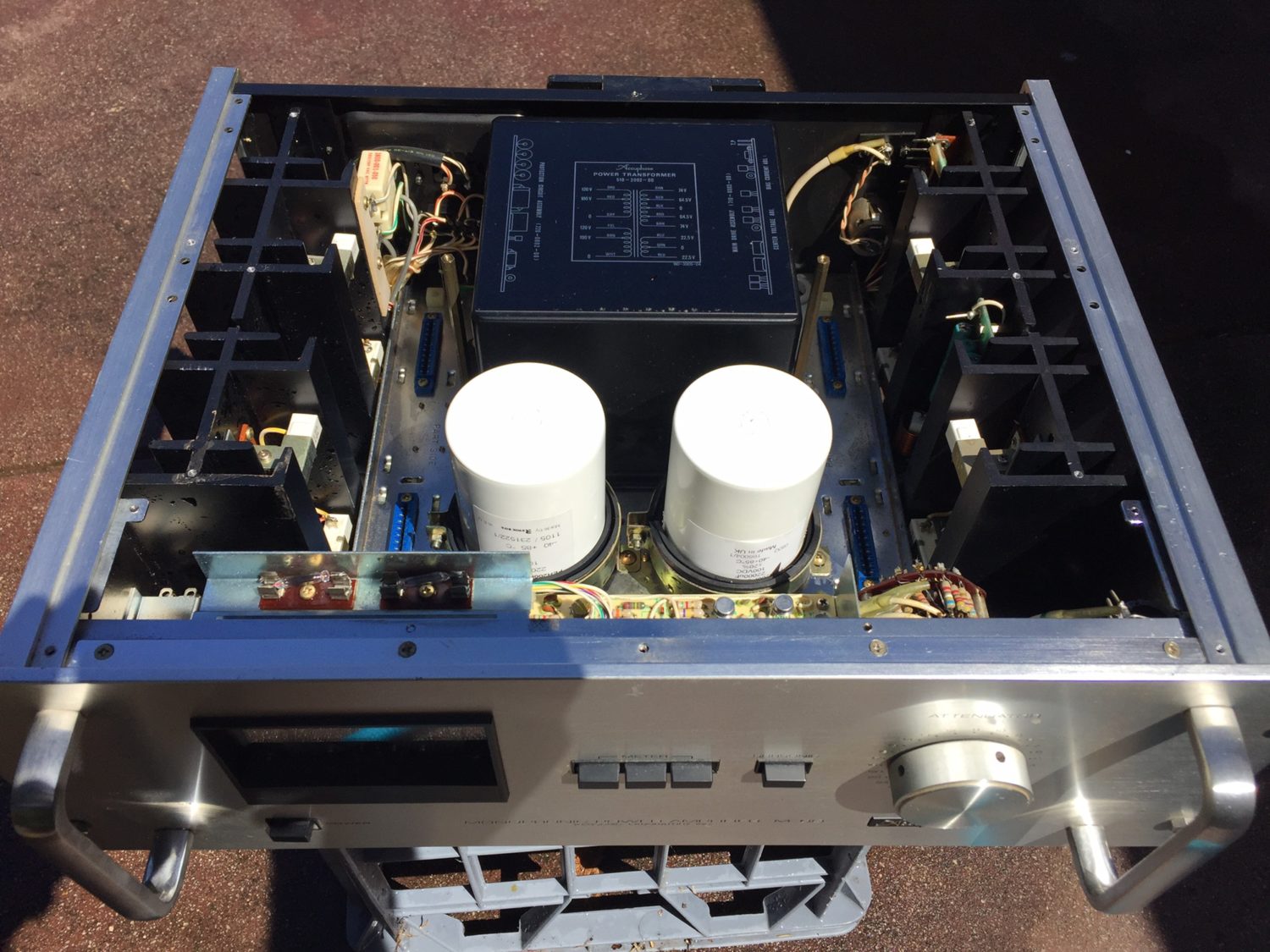
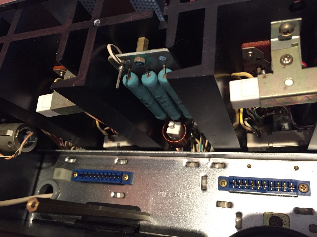
With all my restorations, things begin with a careful and thorough visual inspection, so that I can find out what I’m working with. I make note of critical issues and then proceed with the disassembly.
Once I’d removed the modules from the first Accuphase M-60, I took the first chassis outside for a thorough wash. I use a process I’ve developed for washing amplifiers and it works incredibly well for removing years of baked-on dust and dirt. No other method I’ve tried cleans a chassis as effectively. Whilst the chassis was drying, I disassembled and cleaned the second amplifier chassis and also set it to dry.
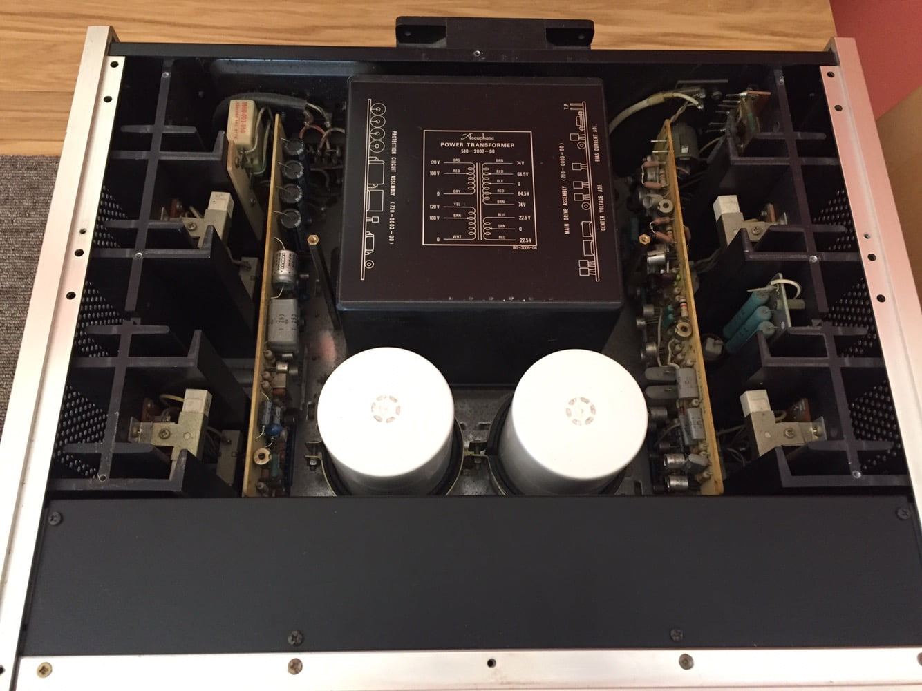
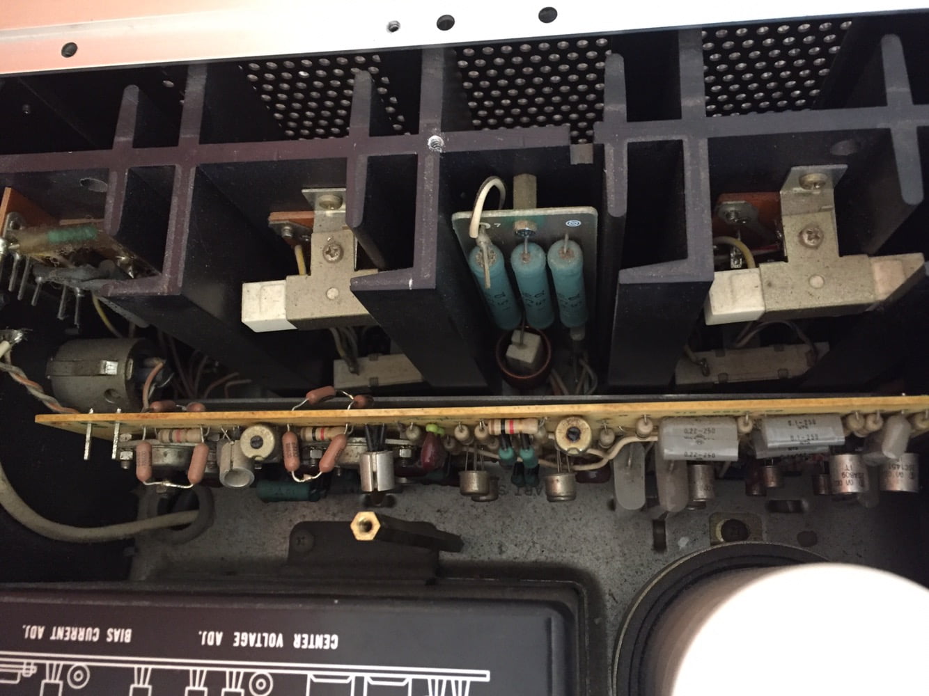
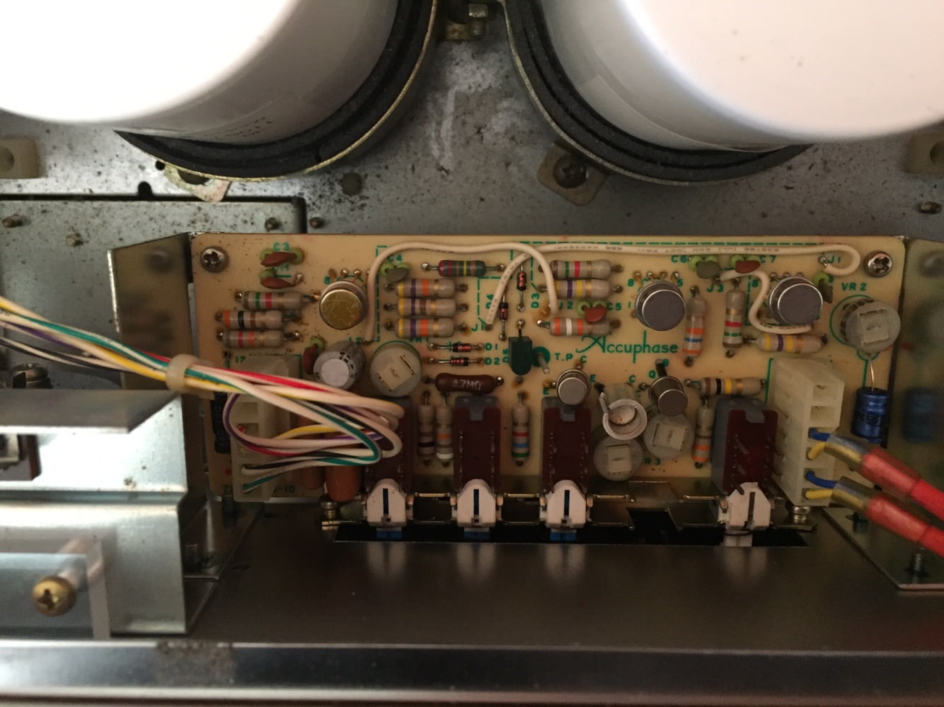
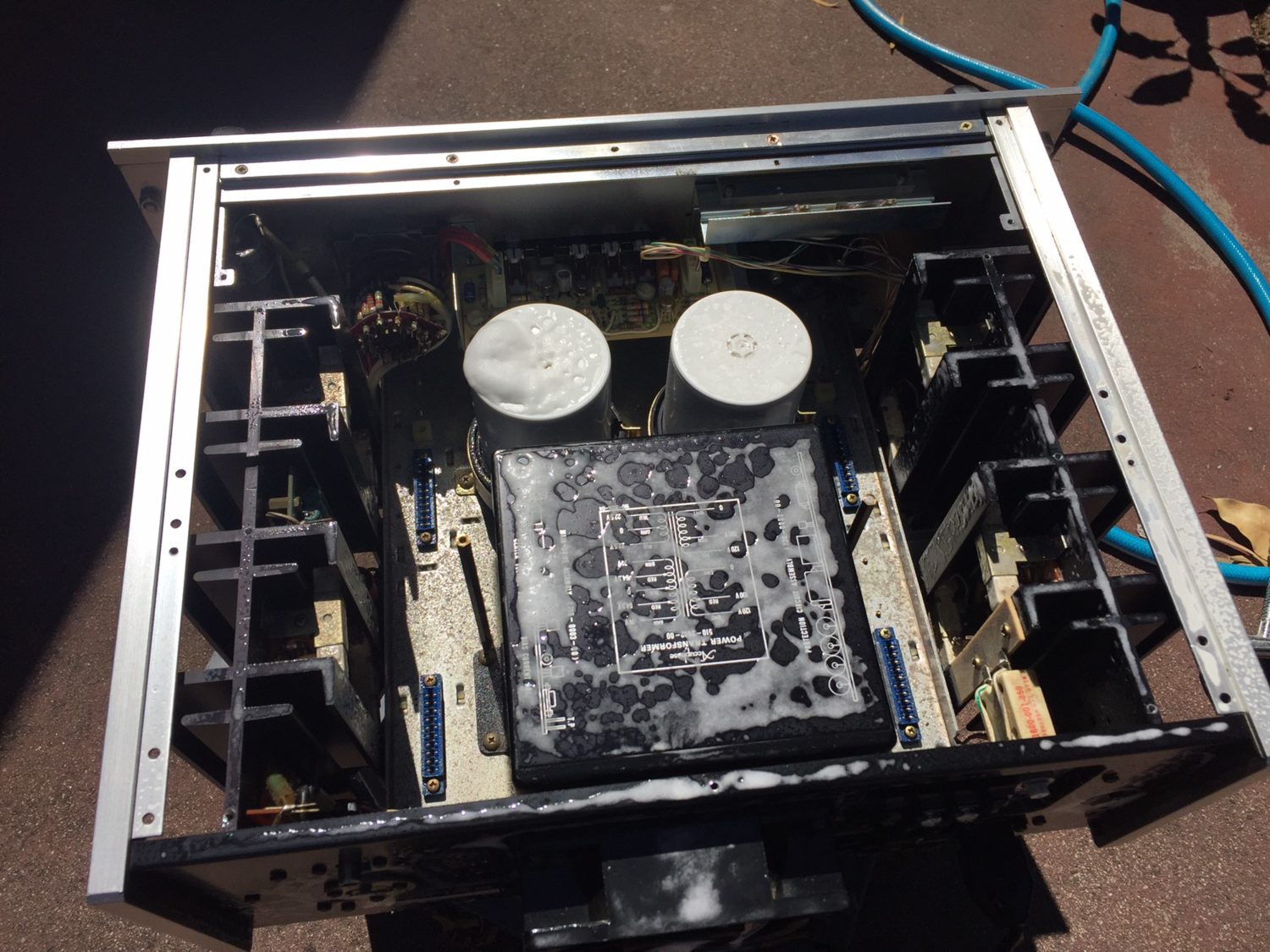
Restoring the Modules
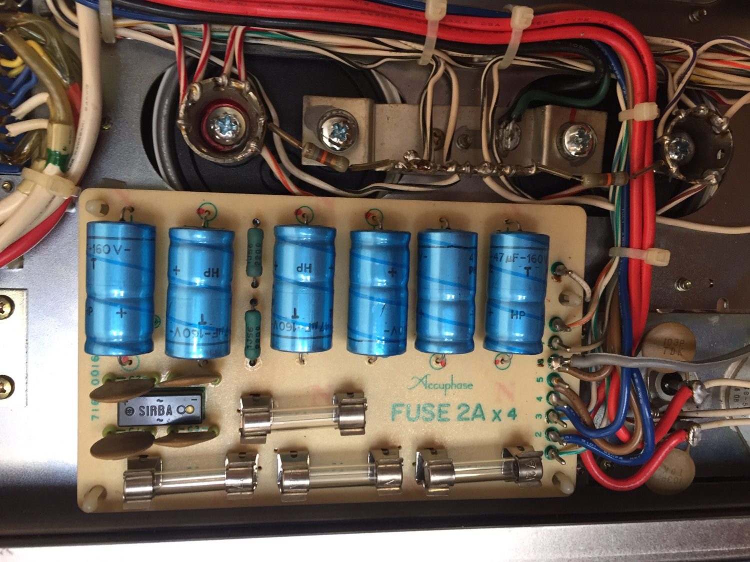
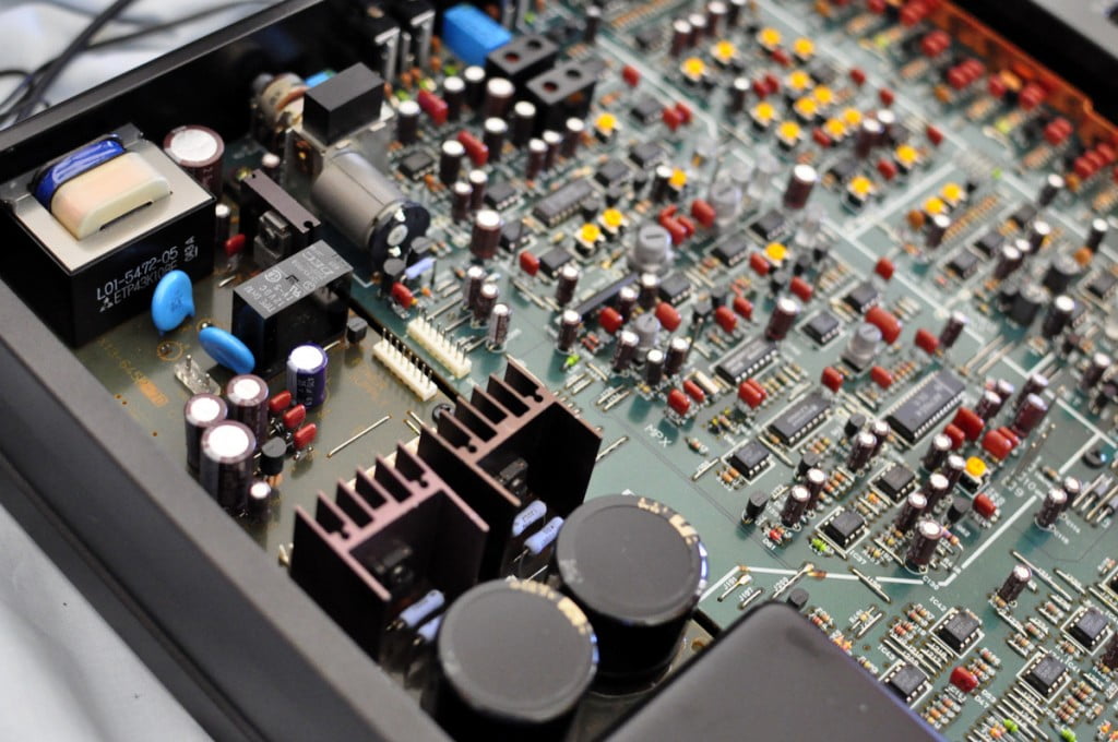
Whilst the chassis were drying, I set to work on the modules, choosing the same modules from each amp, one at a time, to allow duplication of my workflow. I cleaned each board individually, starting with a wash to remove dust and dirt. I then removed all the cheap Chinese capacitors and replaced them with brand new laboratory-grade parts. Where possible, I re-used a couple of the original Elna bipolar electrolytics as they measured better than anything new I had to hand.
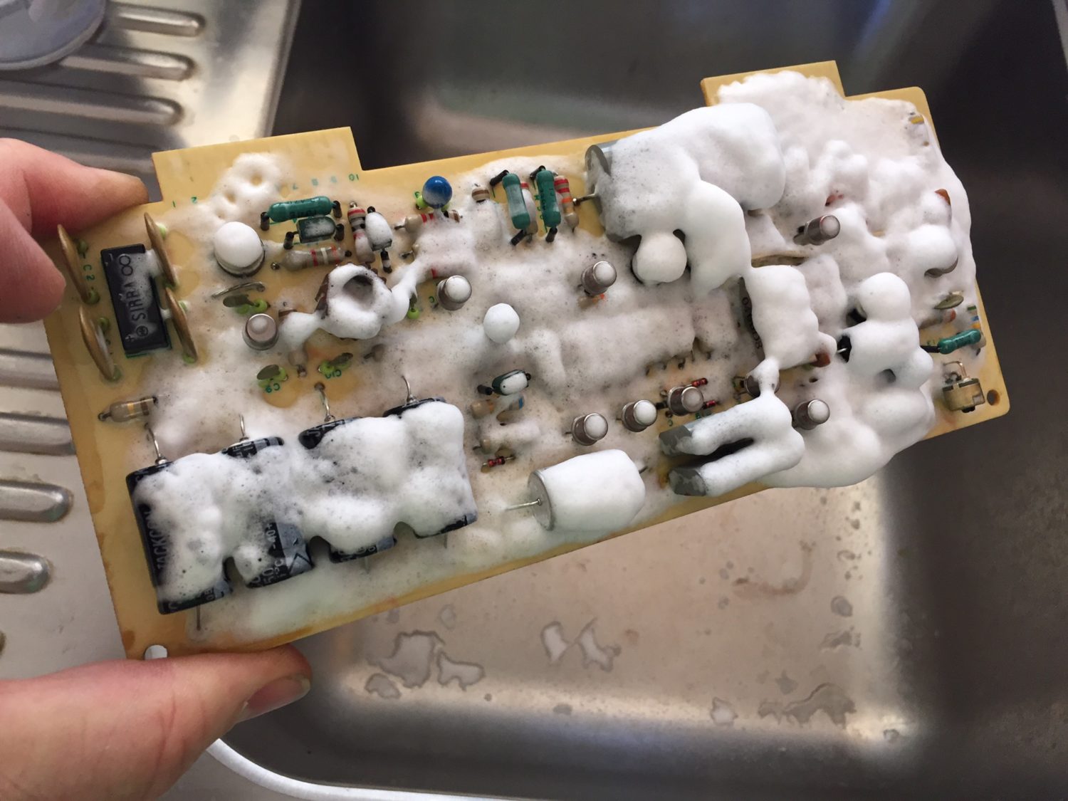
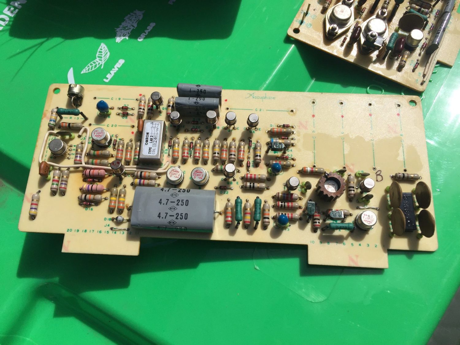
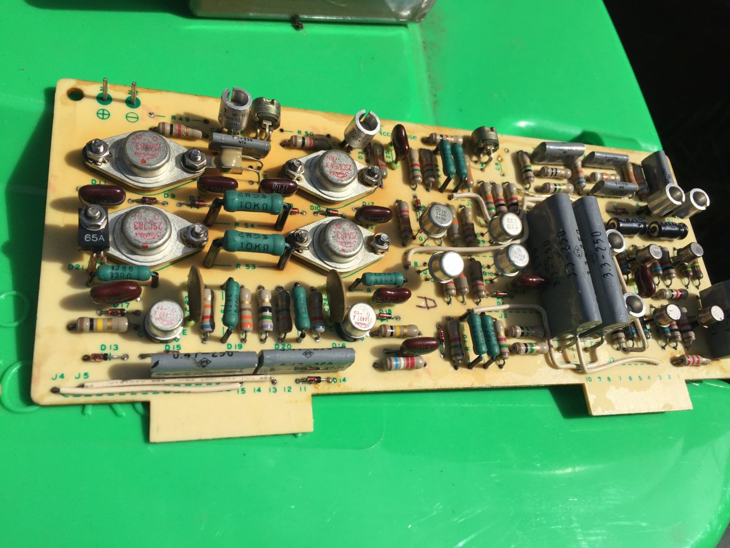
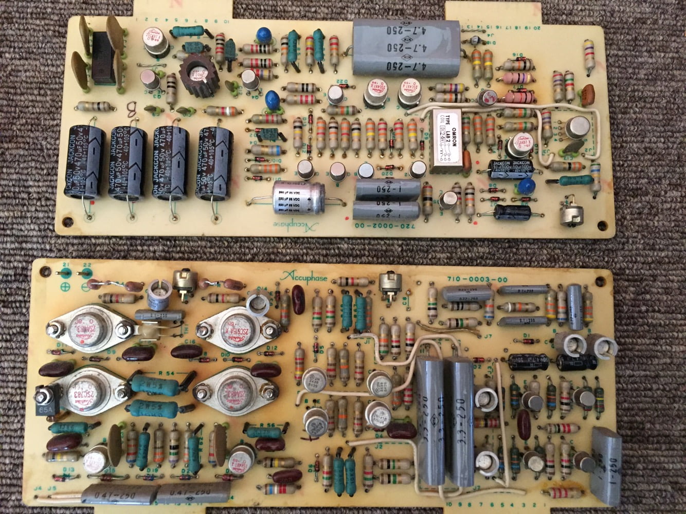
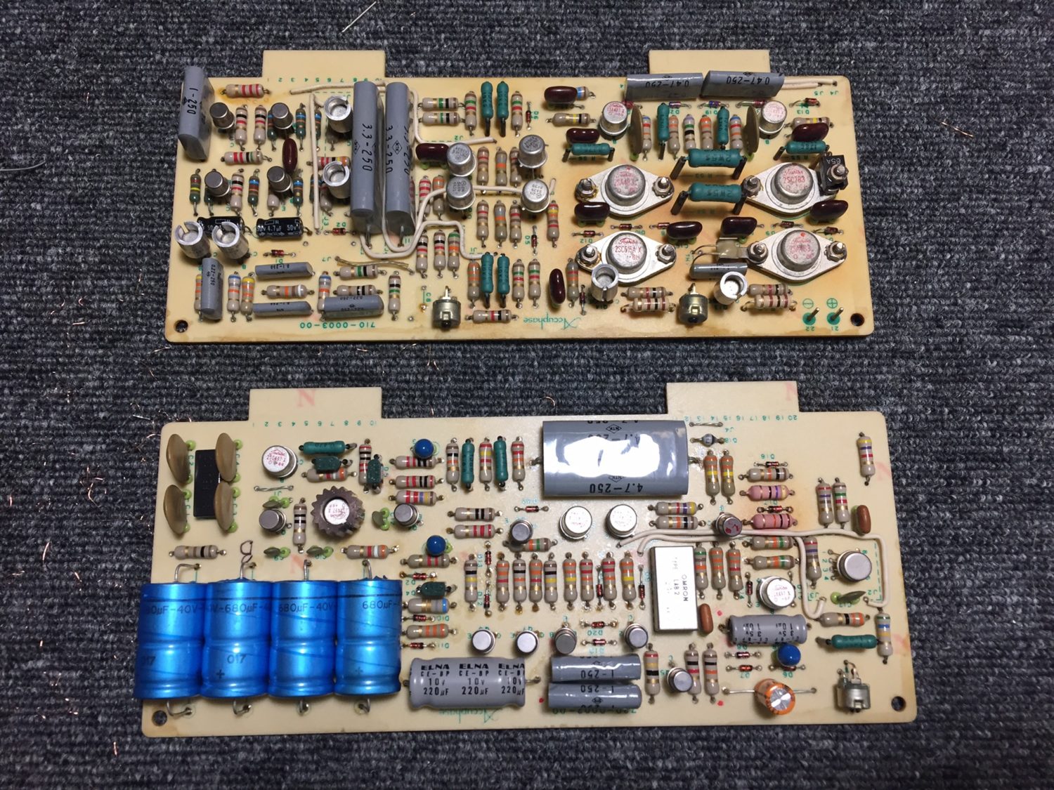
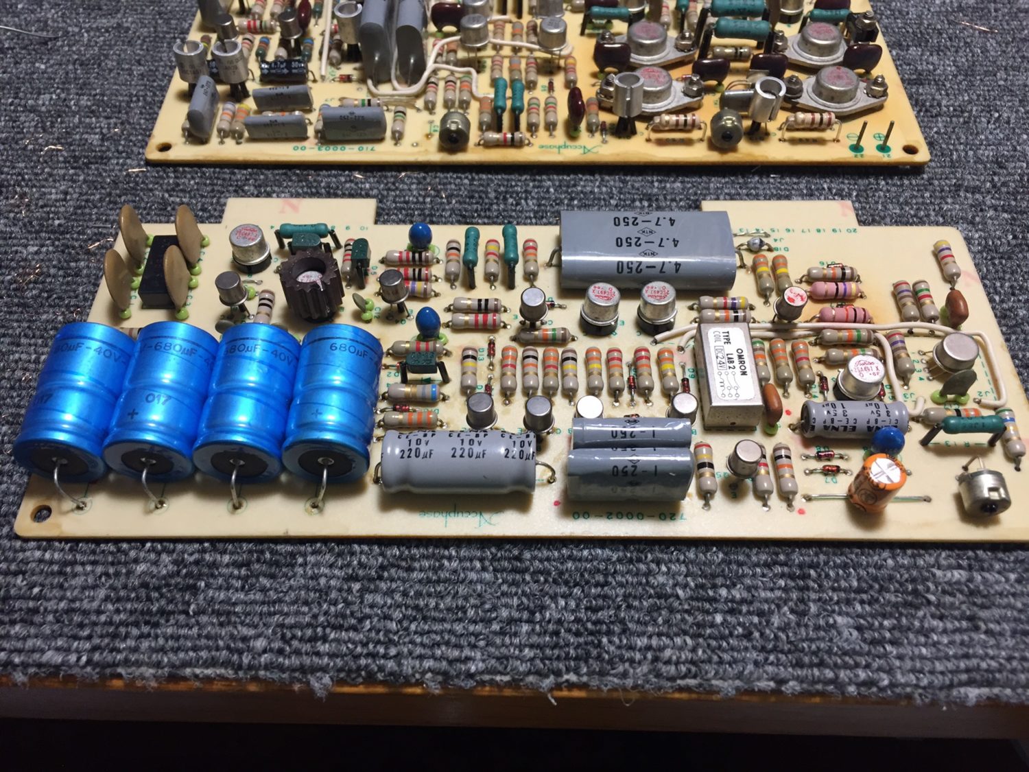
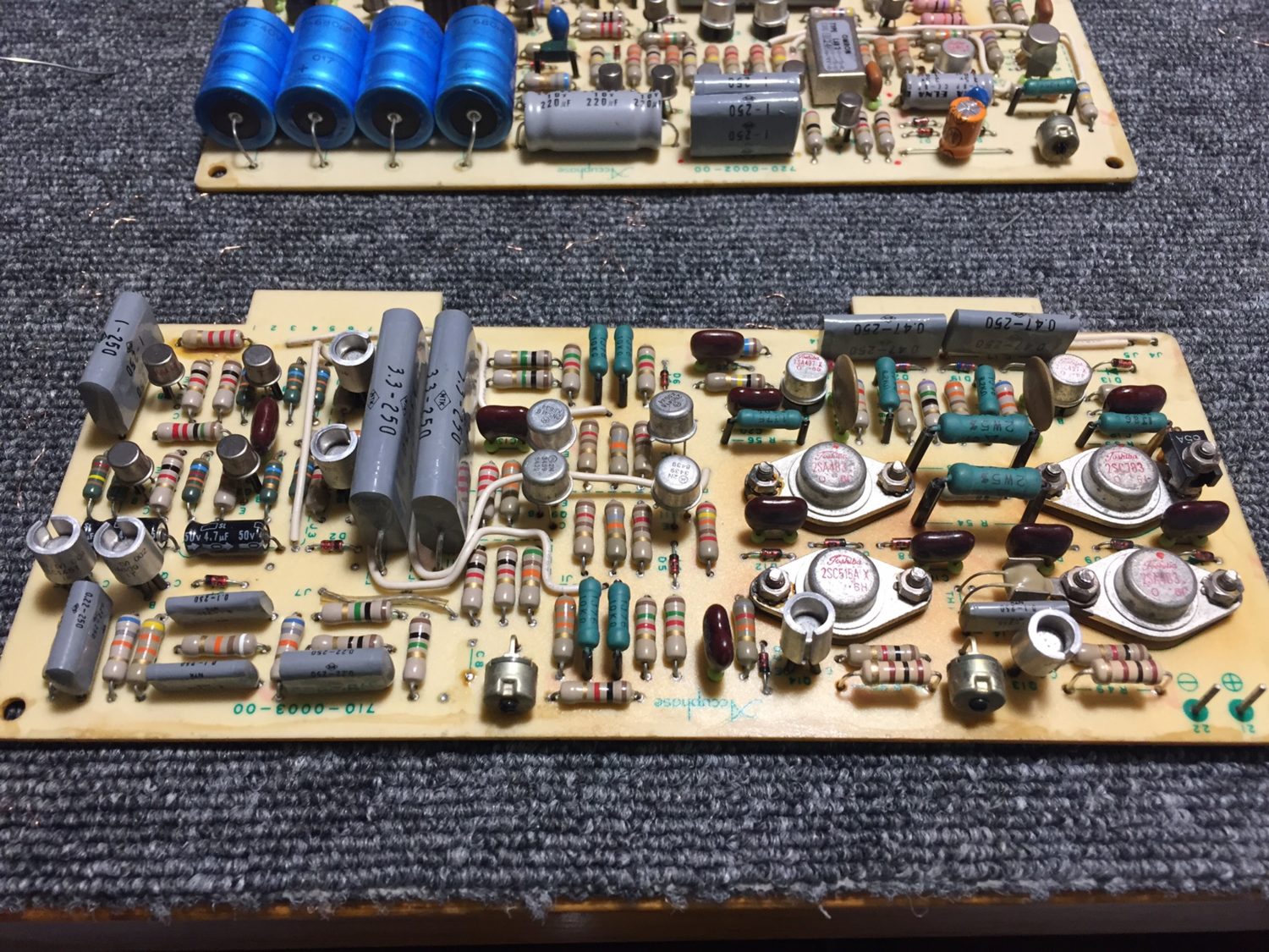
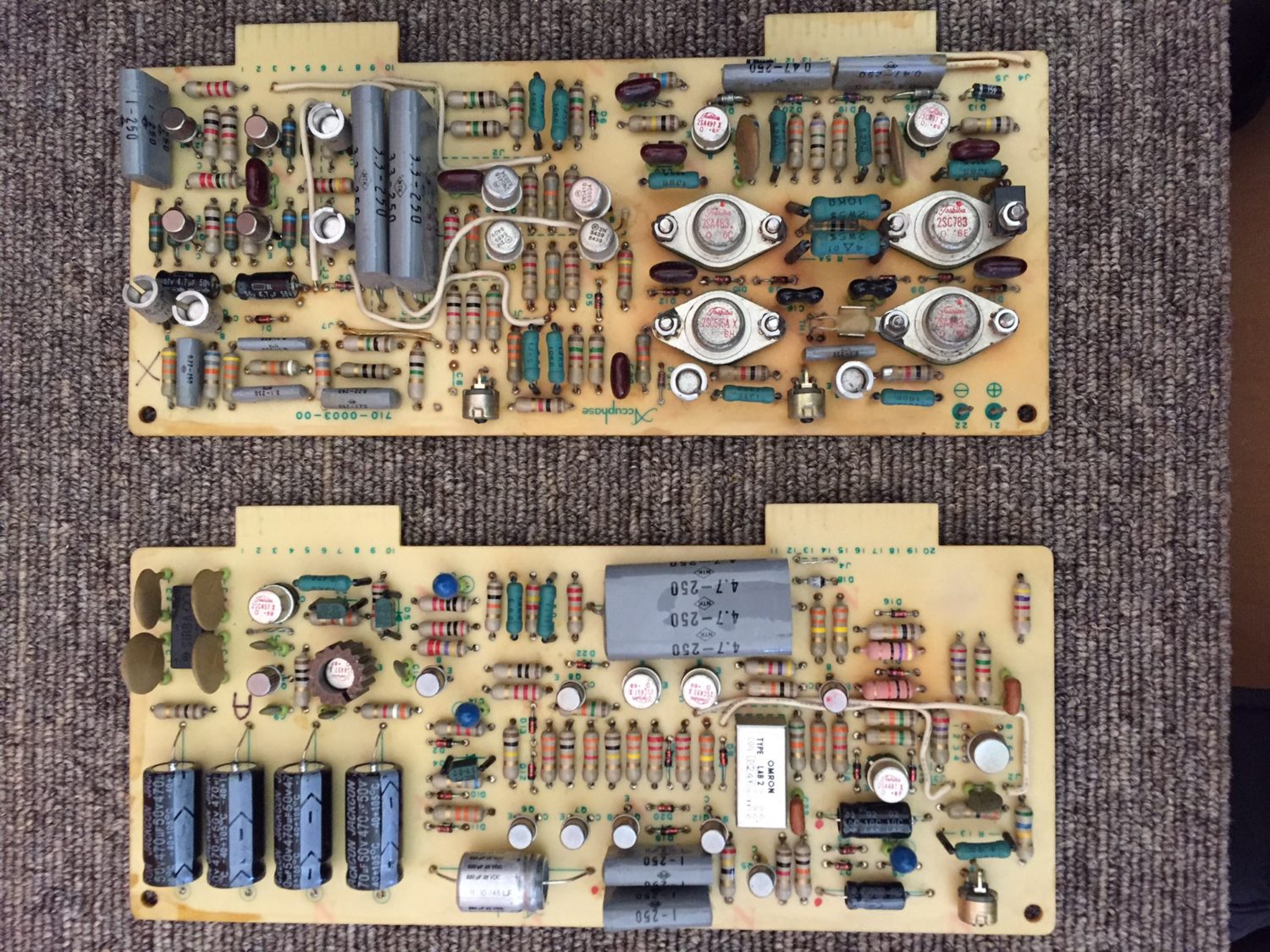
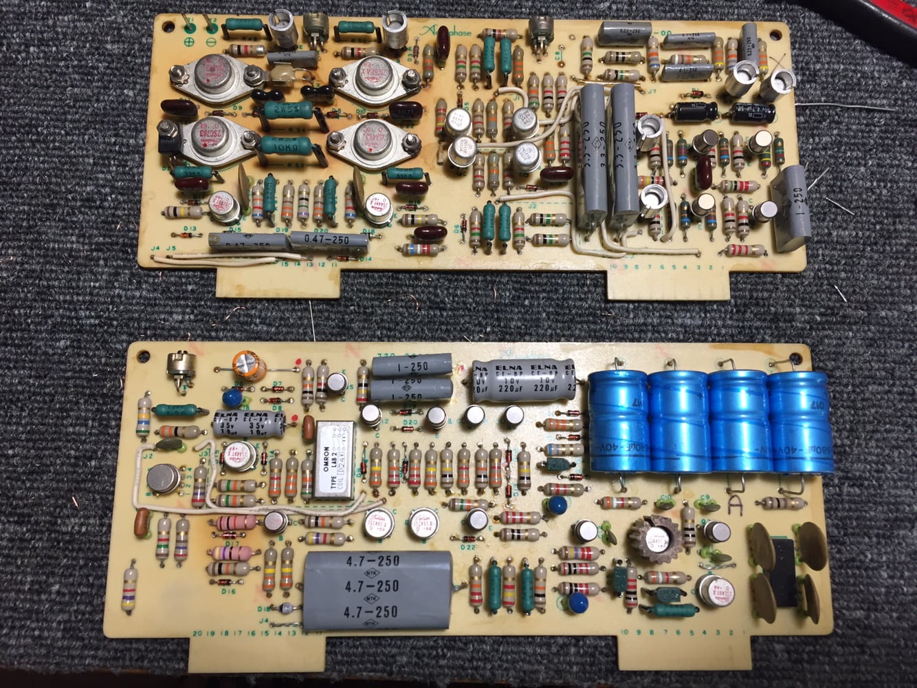
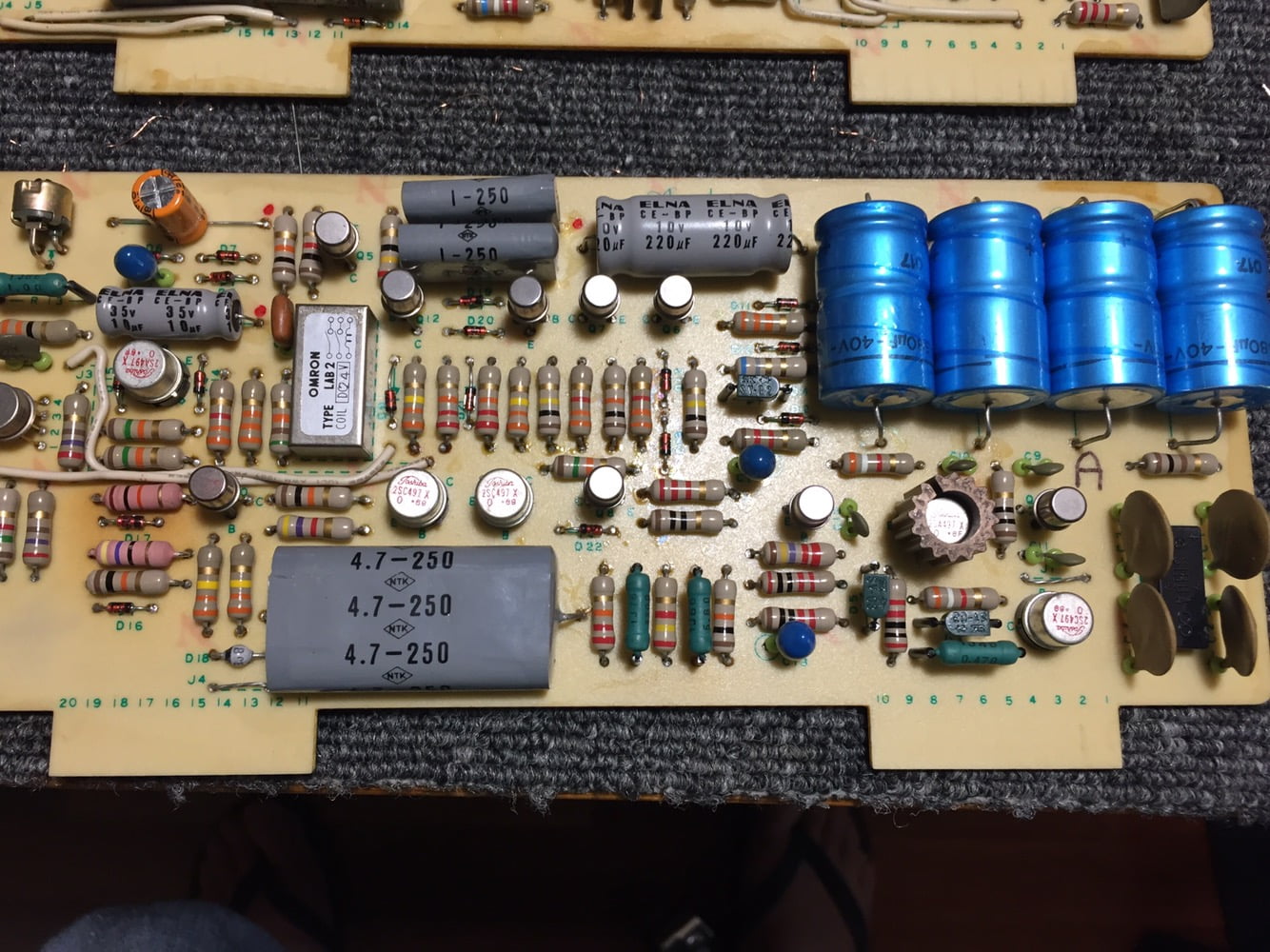
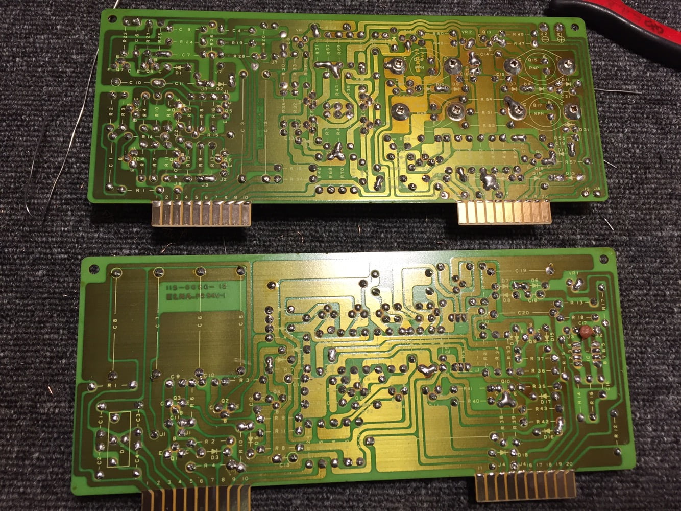
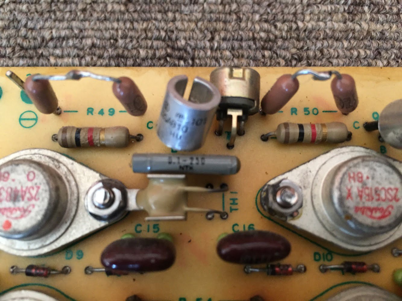
I carefully inspected each driver board and tested components where I suspected trouble. For example, some diodes had been replaced with incorrect parts. I replaced these with the correct value Zeners and a couple of NOS vintage small signal diodes.
The secondary power supply boards also needed work. I reworked dry joints on these boards and a couple of heat-stressed resistors. Strangely, the previous repairer had used good quality vintage axial capacitors on these boards, so these stayed put. and matched the NOS vintage caps I installed on the driver boards.
Output Devices
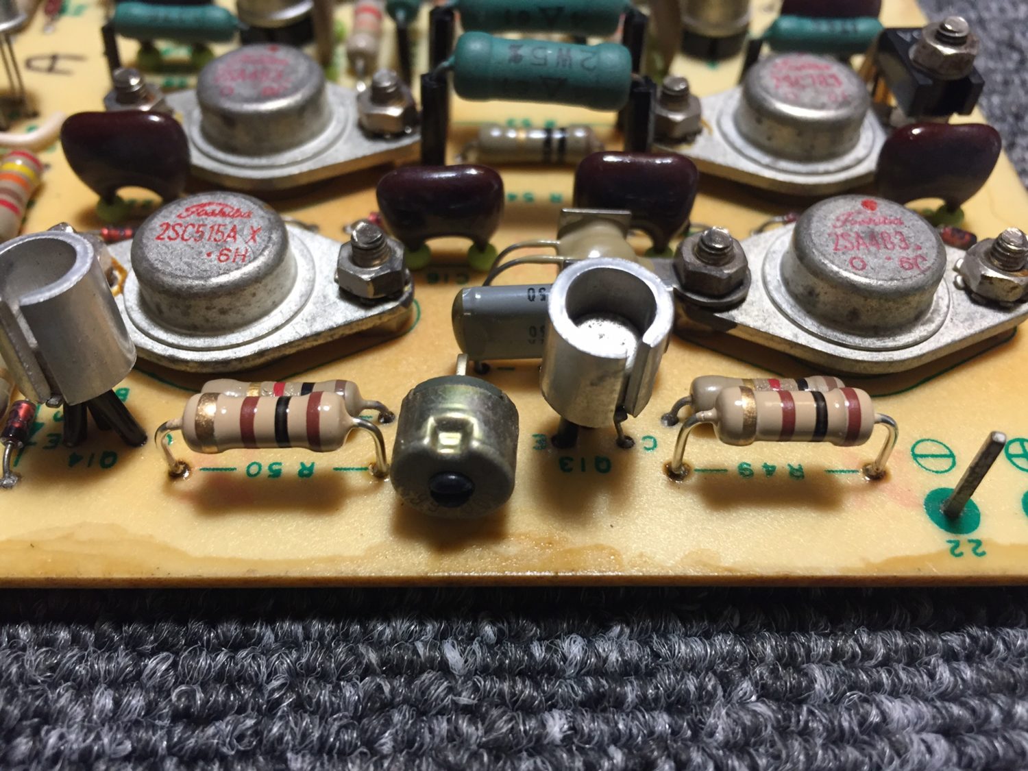
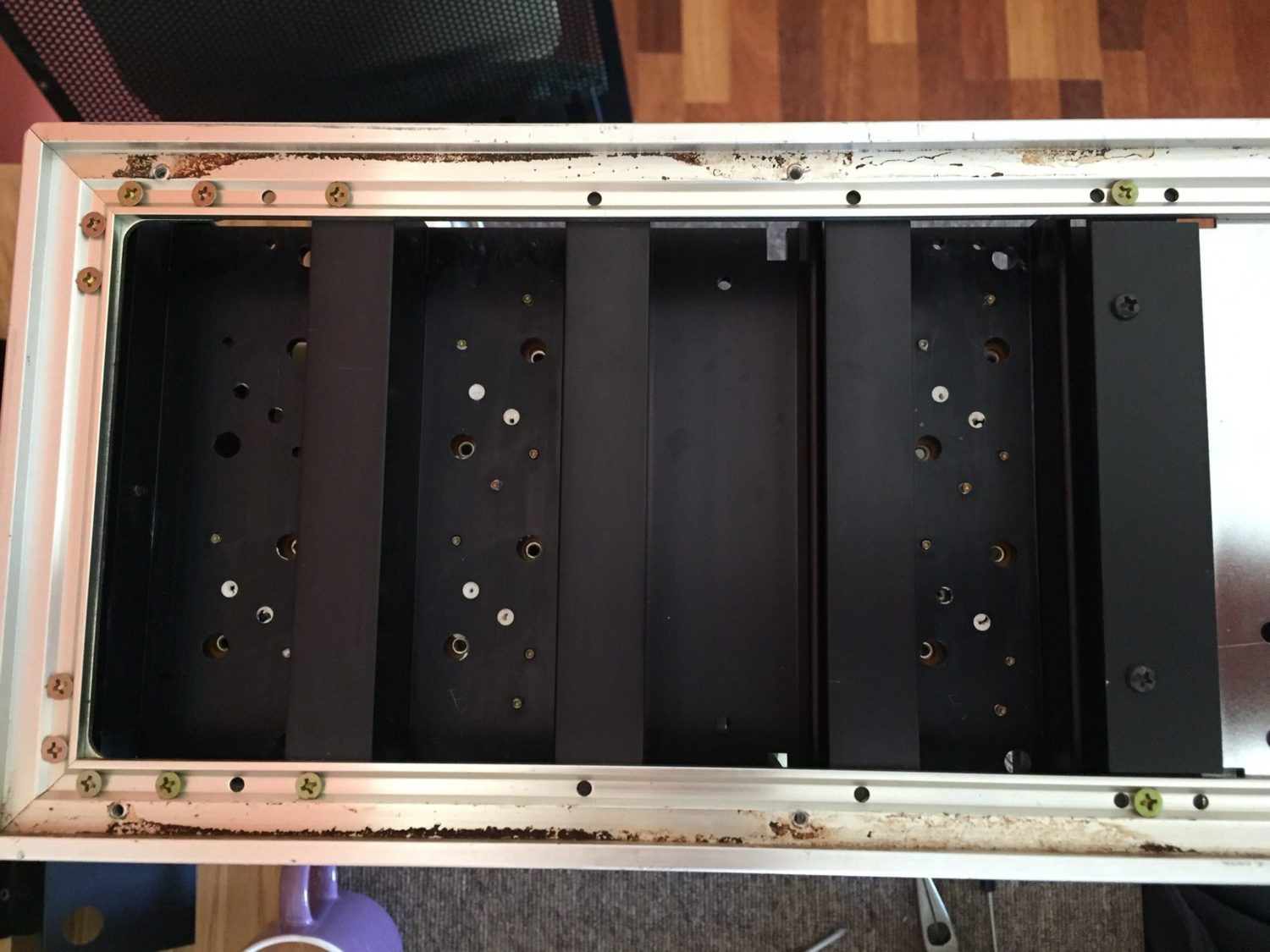
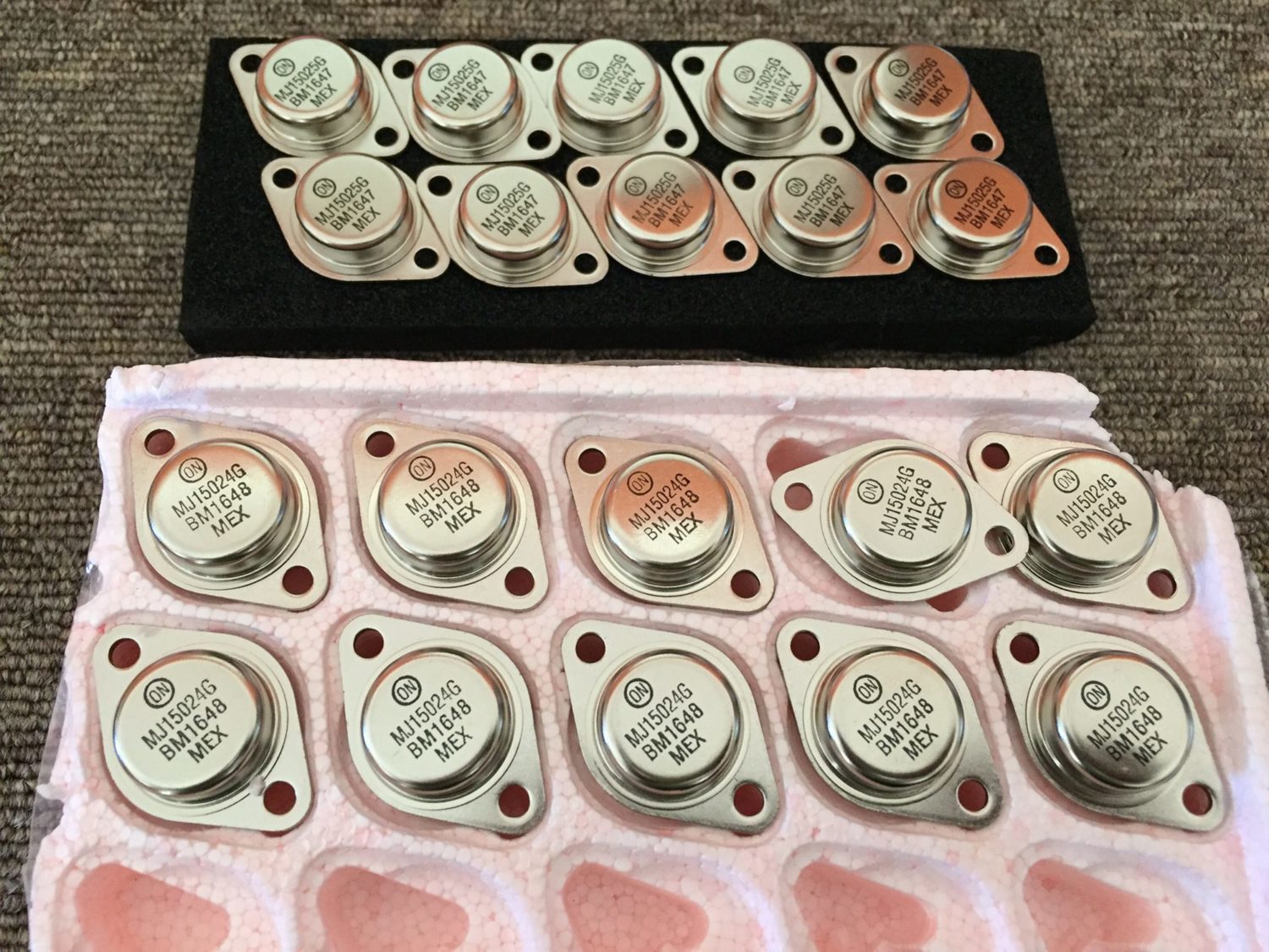
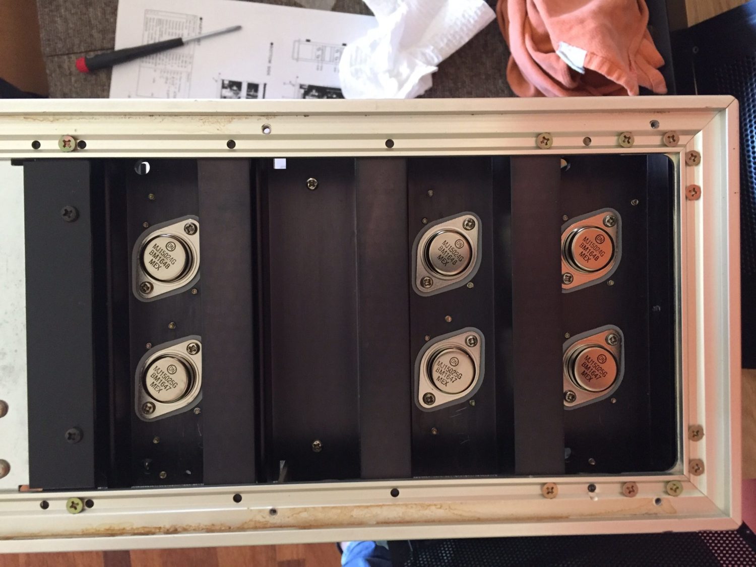
After parts replacement, I carefully reworked dry joints and flux-cleaned boards. I then turned my attention to the output devices. Never before have I seen such a mess. Someone had removed the presumably dead original output devices and replaced then with Motorola MJ15003 and MJ15004 devices – not really a match. Worse still, they were all from different batches and had wildly differing gain!
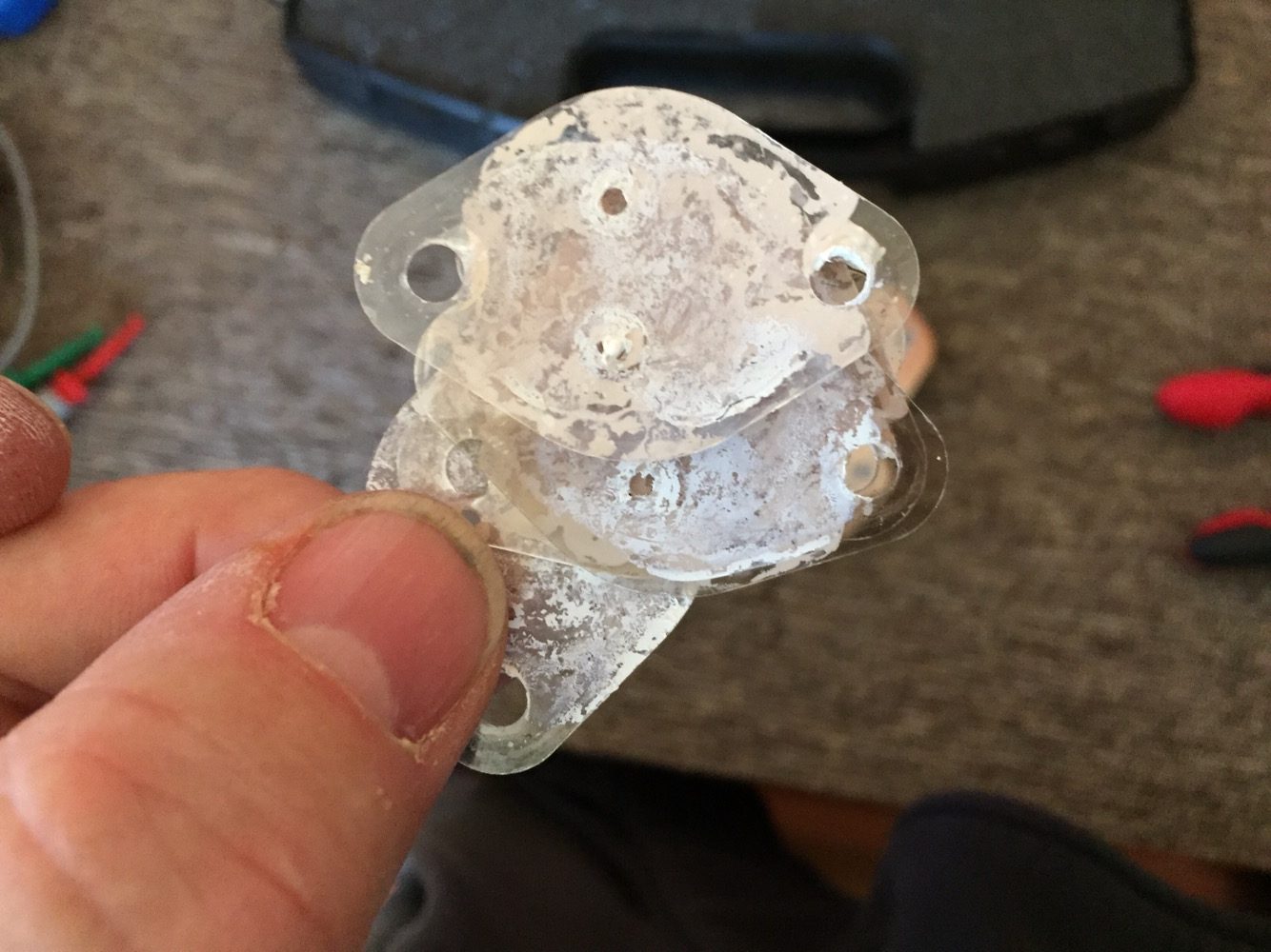
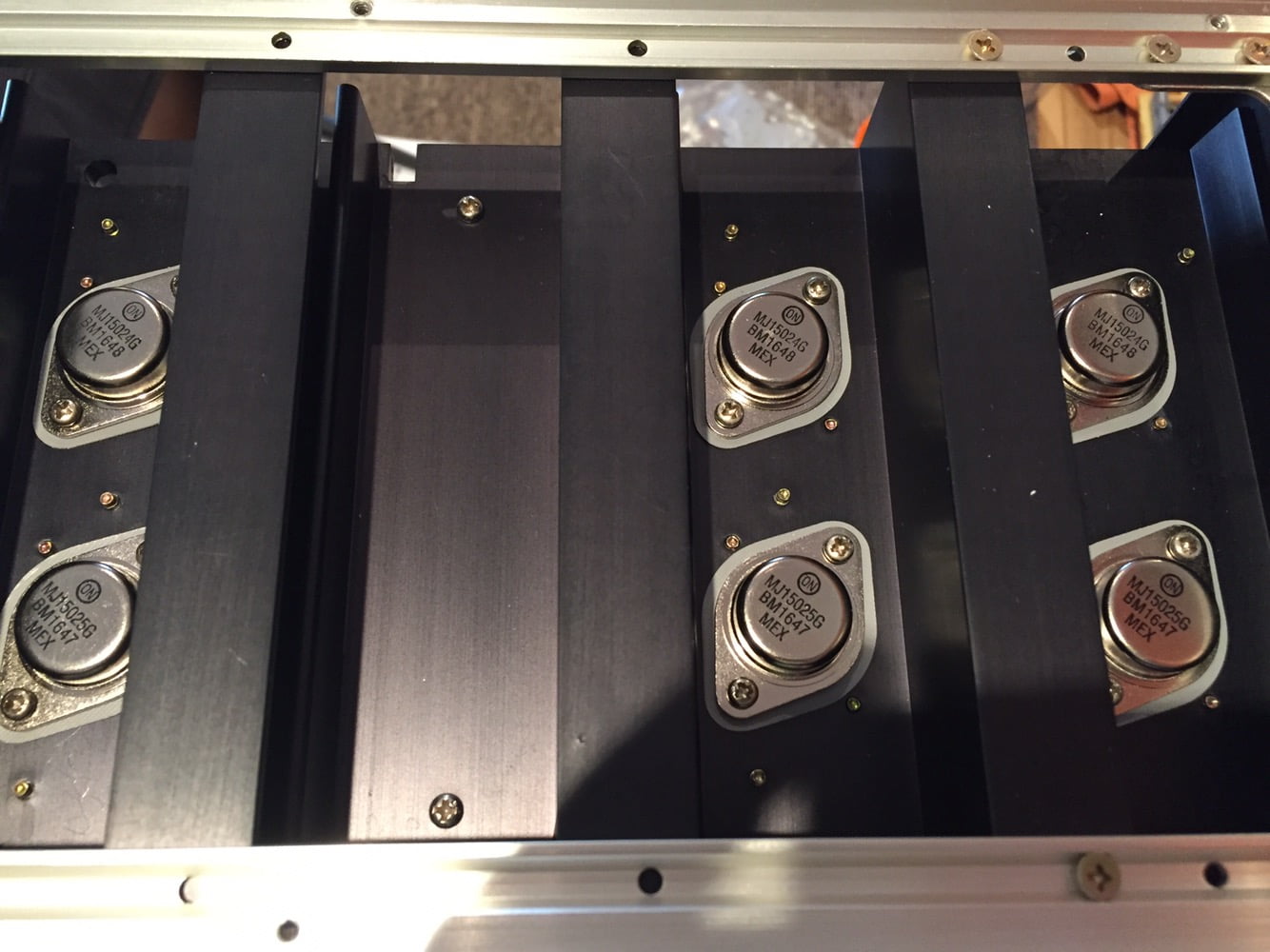
I decided to replace all of these with modern, high-speed, high-voltage transistors. I used parts all from the same batch and I matched them for gain. After removing the old parts and the mica thermal washers and dried thermal paste, I cleaned the heatsinks and remounted the new devices on silicone thermal washers.

Reassembly & Final Touches
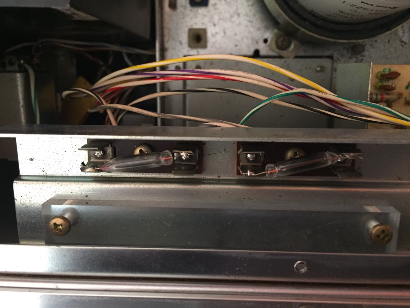
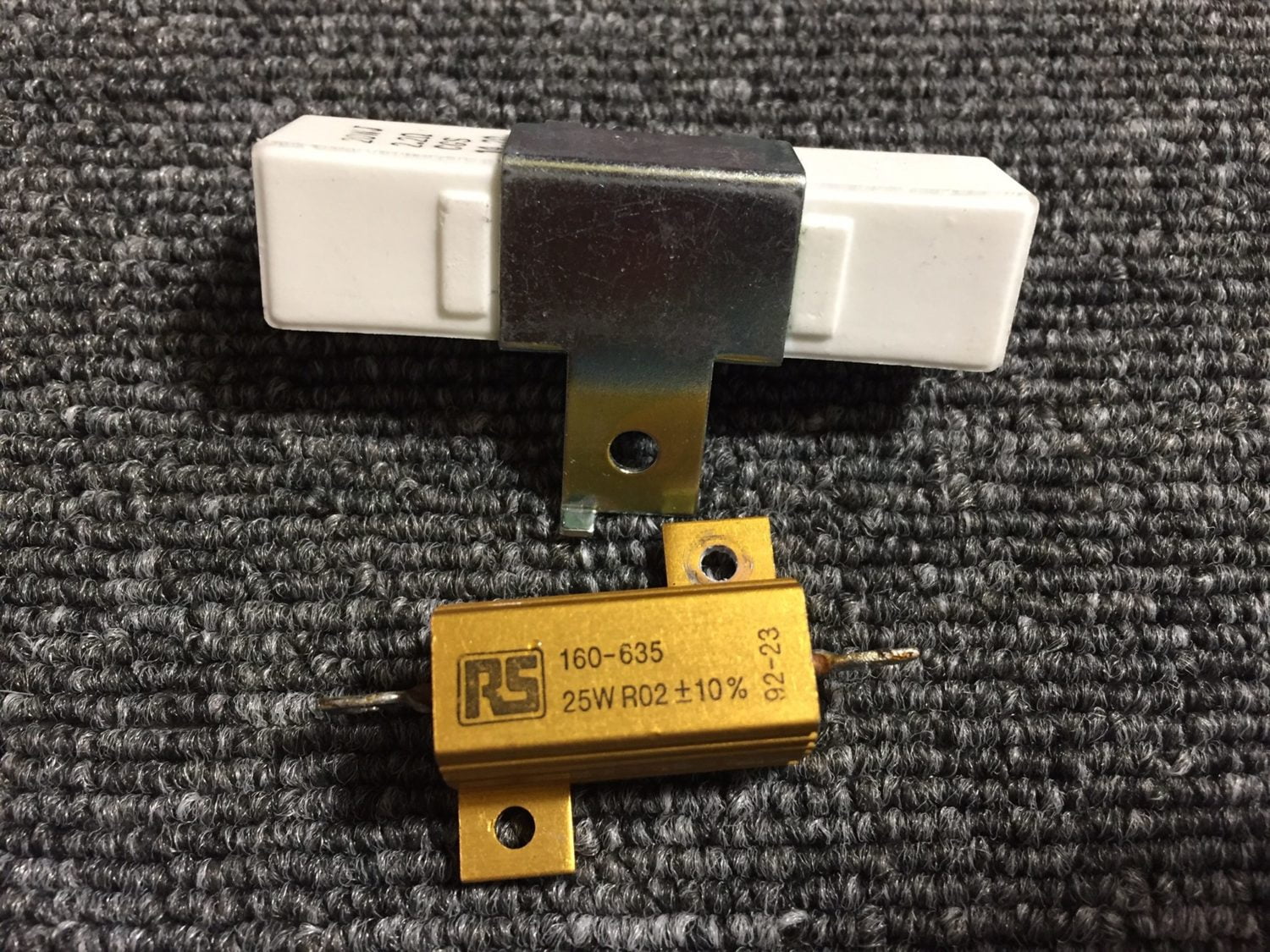
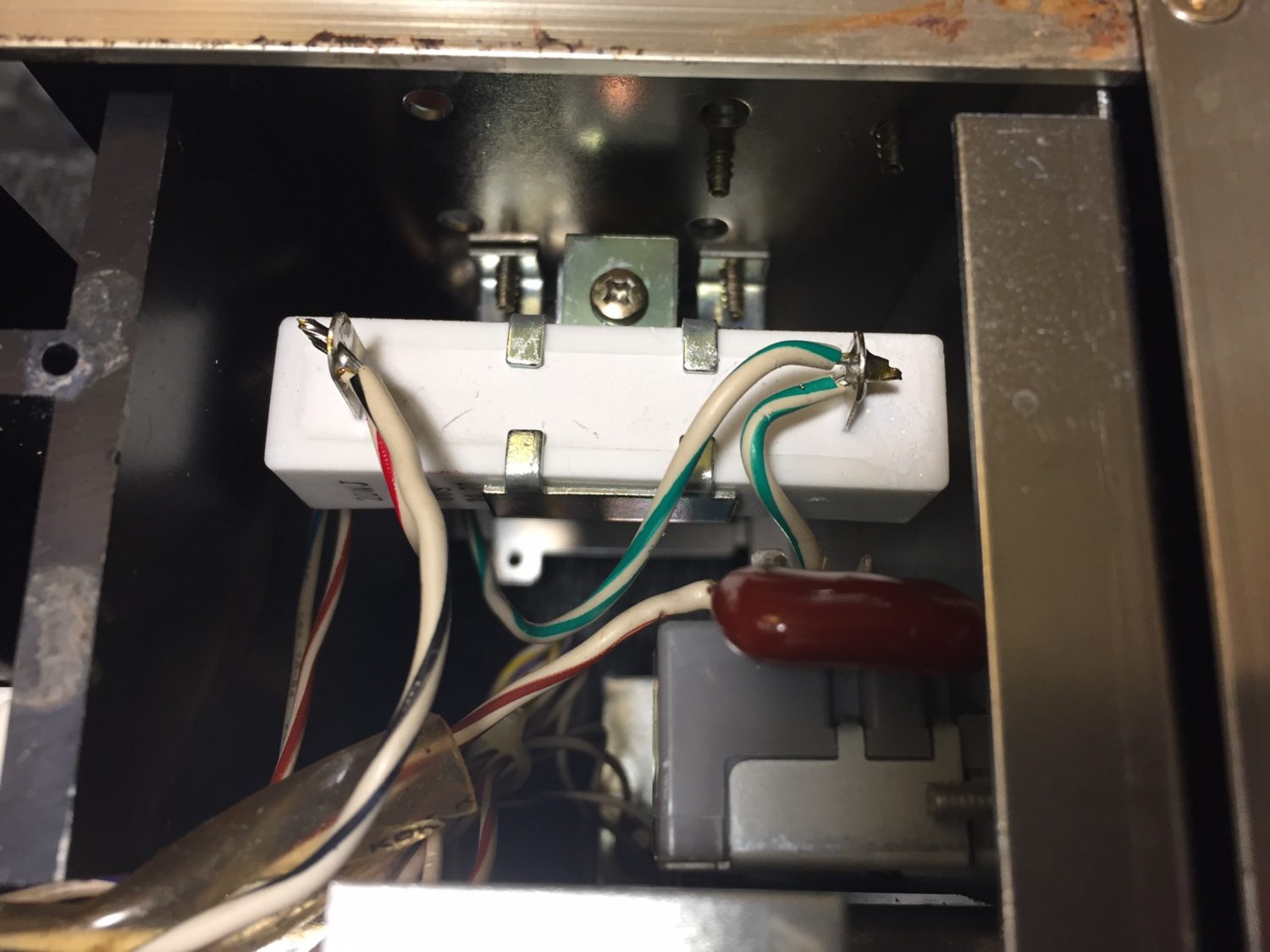
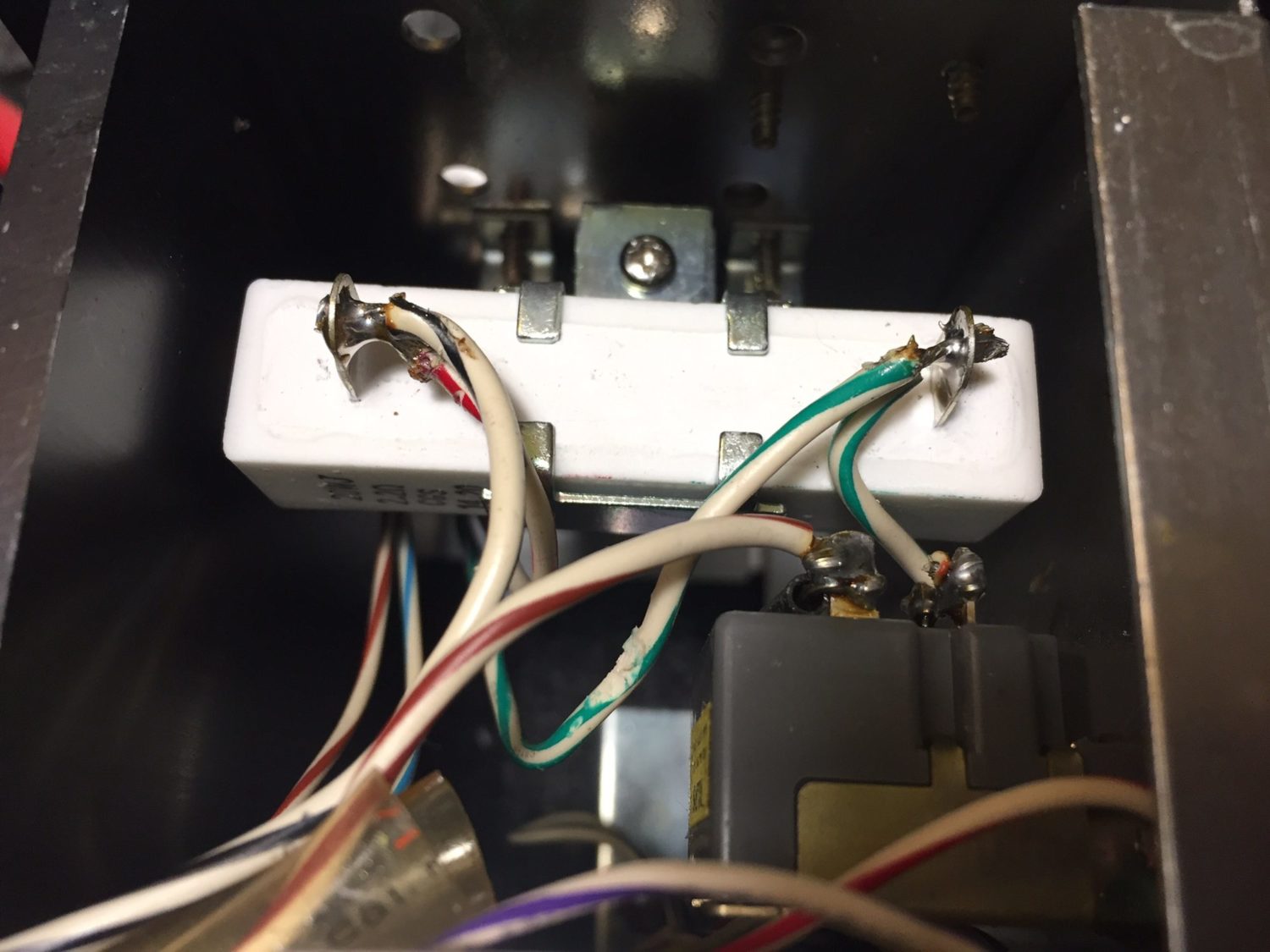
There were a few more steps. I replaced the meter illumination and the soft-start resistors. These resistors allow the current impulse drawn by the amp to be spread over time, reducing the chances of blowing a house fuse upon startup and making things easier on the amps. Again, these had been replaced with the wrong parts at some point in the past, so I ordered exact factory replacements and installed them.

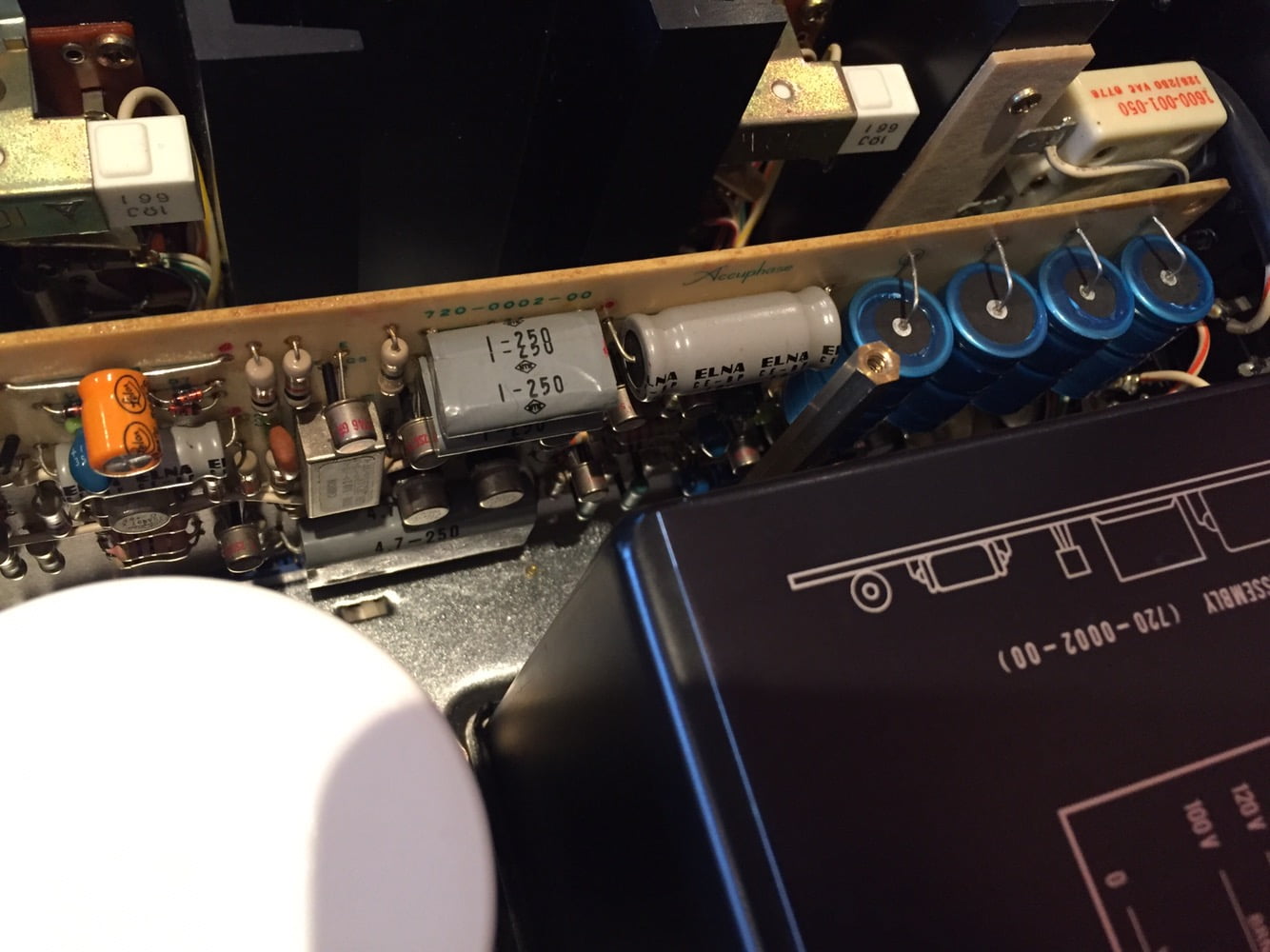
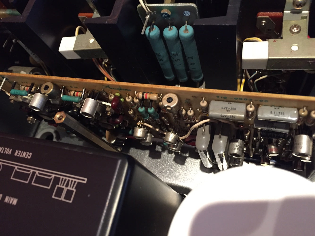
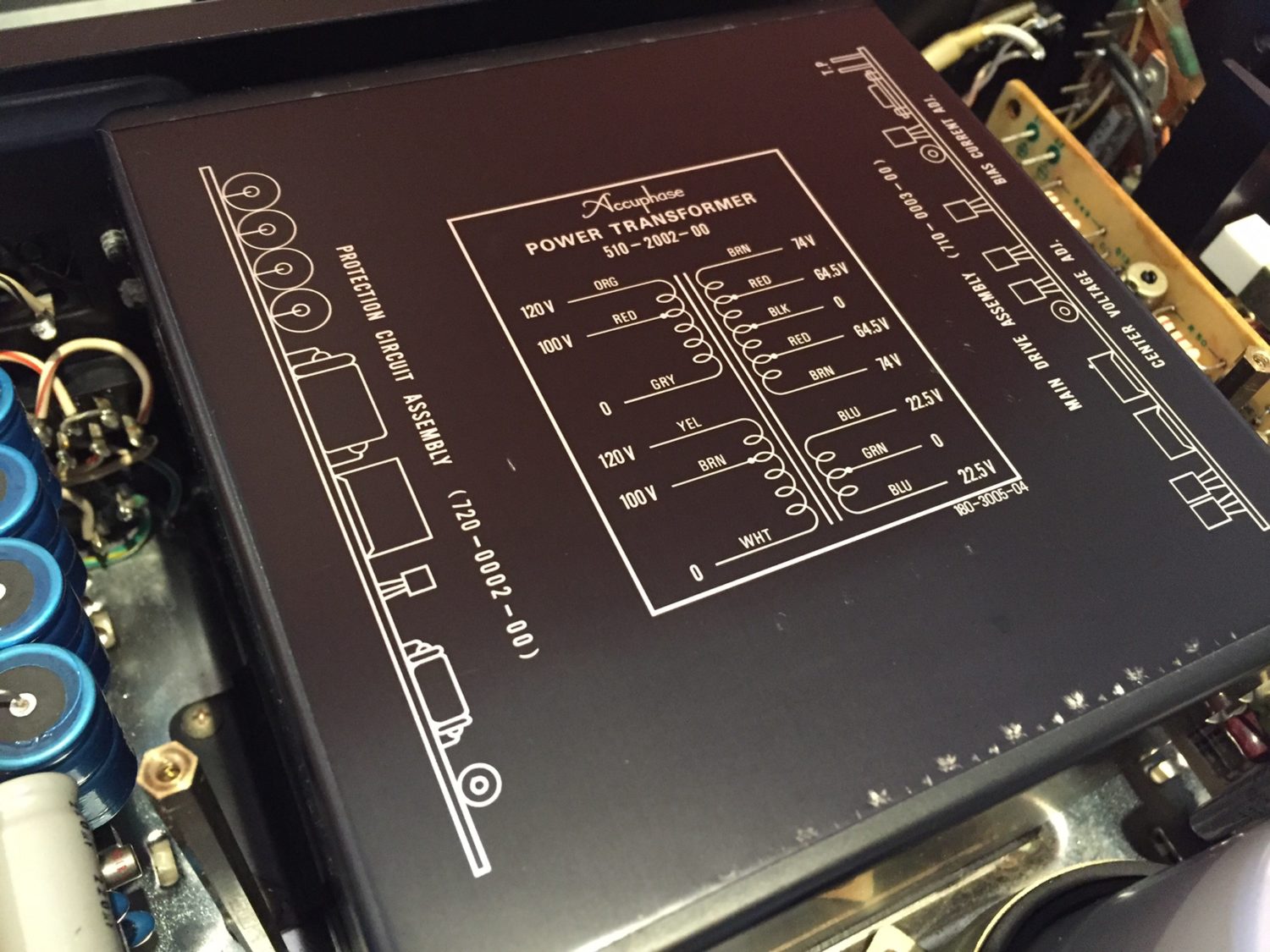
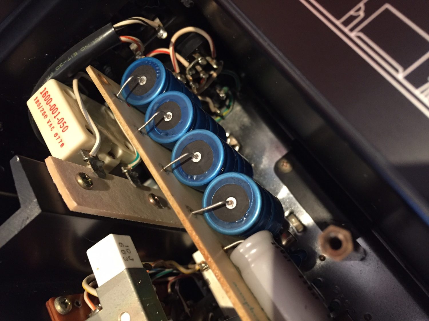
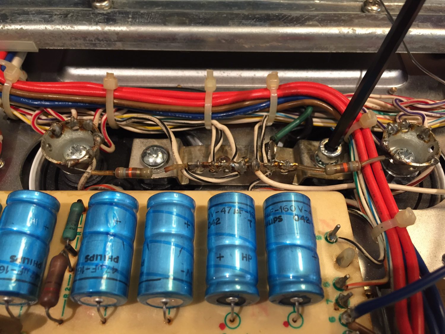
The guitar amp guy replaced the main filter capacitors. This was totally unnecessary, I tested the original, beautiful Elna capacitors, they were perfect. The only saving grace is that he used very good RIFA capacitors. RIFAs are a premium spec part, so I left them. However, he used cheap hardware to complete the filter cap wiring and so I replaced this with stainless Allen fasteners.
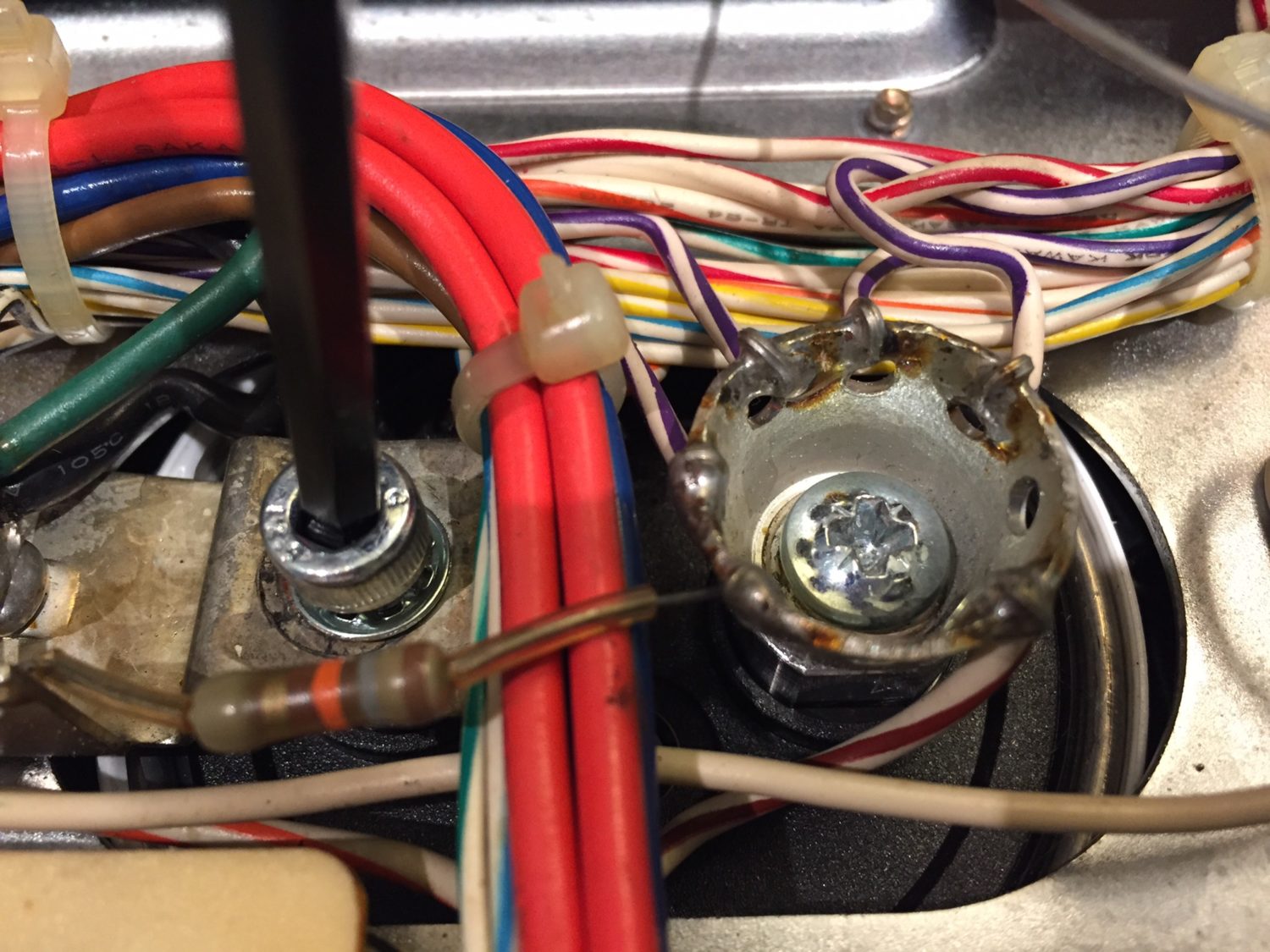
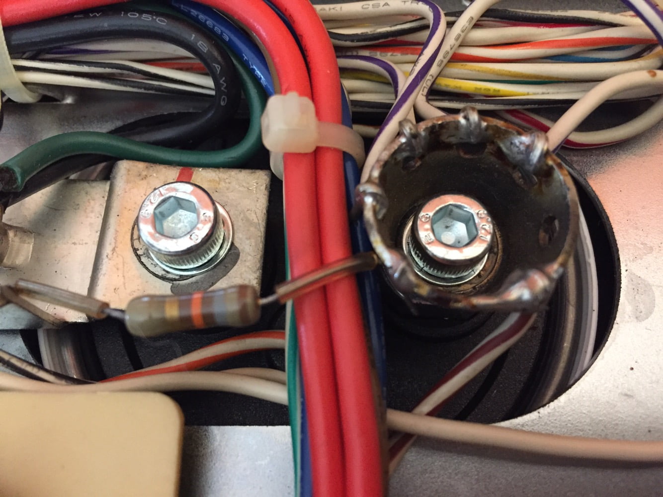
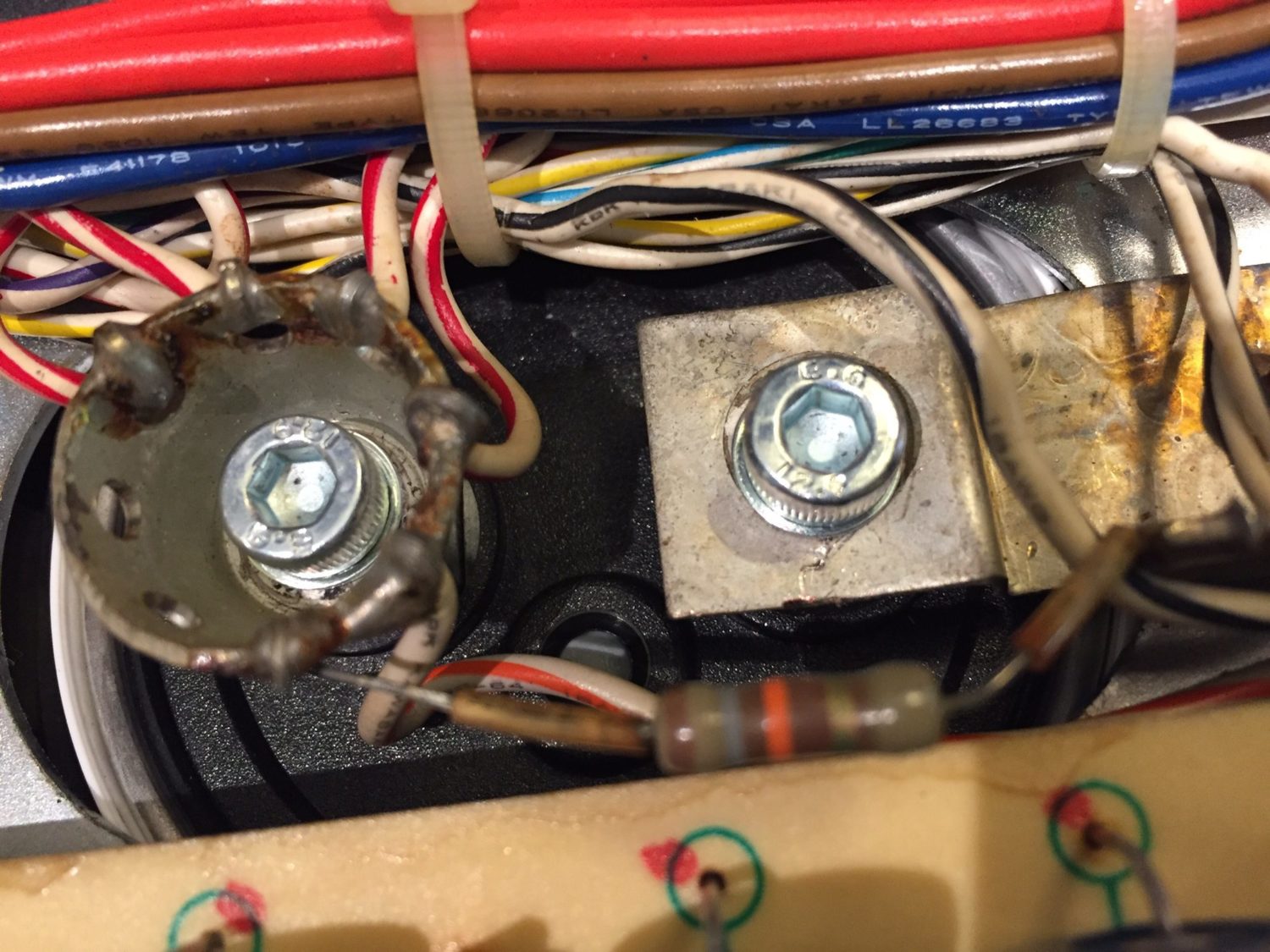
Finally, I applied contact cleaner/enhancer to all board-to-board connectors switches and attenuators.
Testing & Adjustment
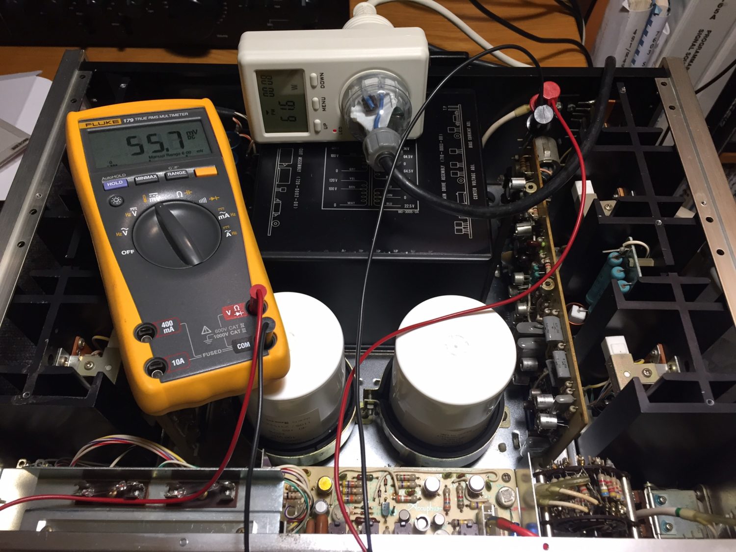
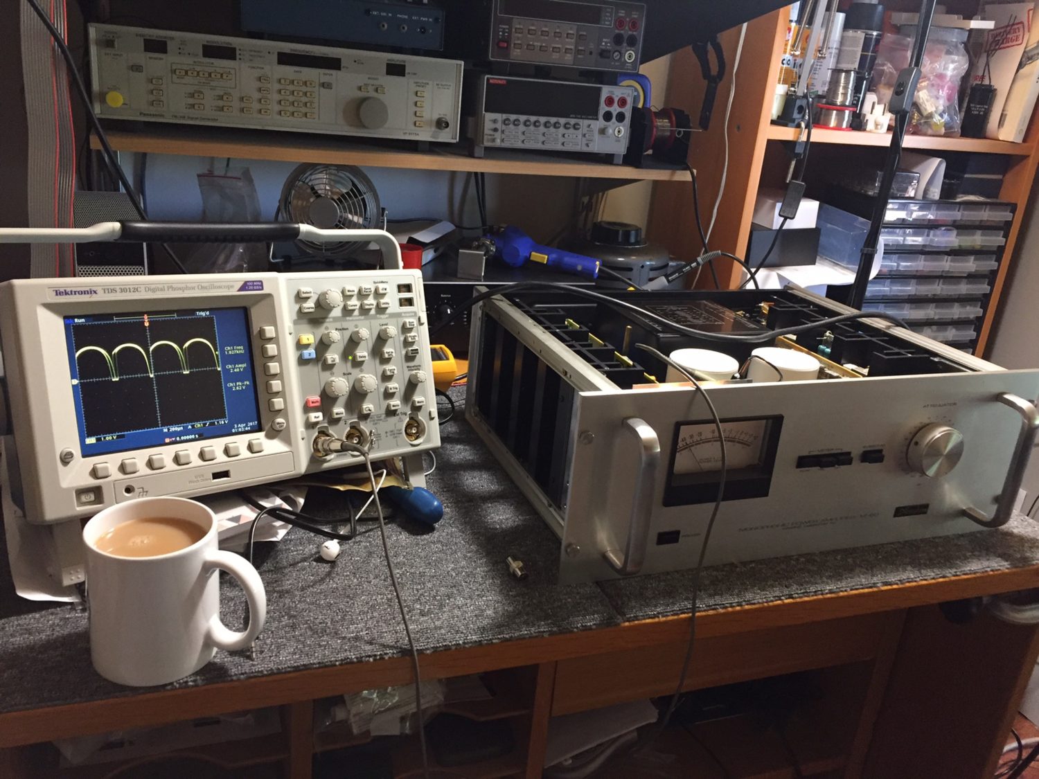
I powered the Accuphase M-60 monoblocks up on a variac, one at a time, whilst closely monitoring current draw. The variac allows me to make sure everything is OK and that the amp is behaving itself during the gradual ramp-up to full mains voltage.
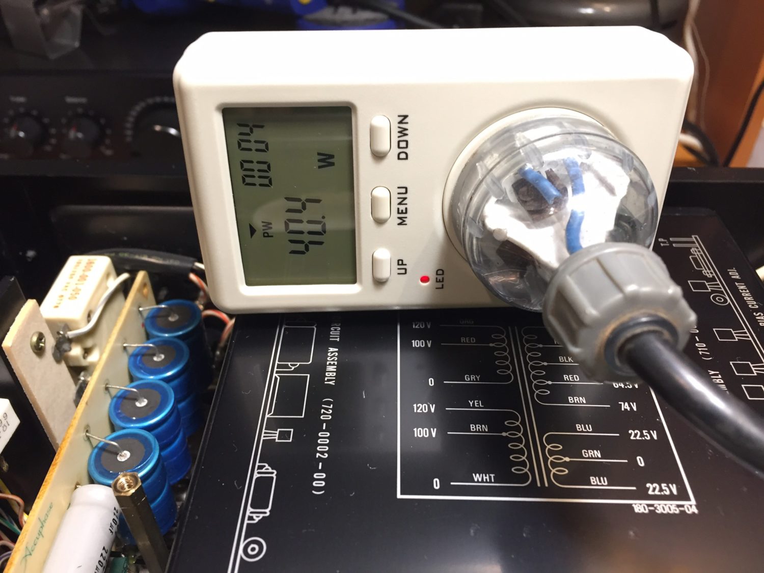
Once they were up and running on 240V, I left each amp for a few minutes to stabilise and then carefully dialled in the correct amount of bias current. Once the bias had stabilised, I adjusted DC offset. Next, it was on to the protection circuit which you test with a 1 Ohm output load.
Finally, I calibrated the meter drive circuitry, using a test signal and output loads. I discovered a little distortion in one amp. I traced it to of all things, an old staple which had found its way into the exposed output relay of one of the M60’s. It was happily part of the circuit until I removed it!
Load Testing
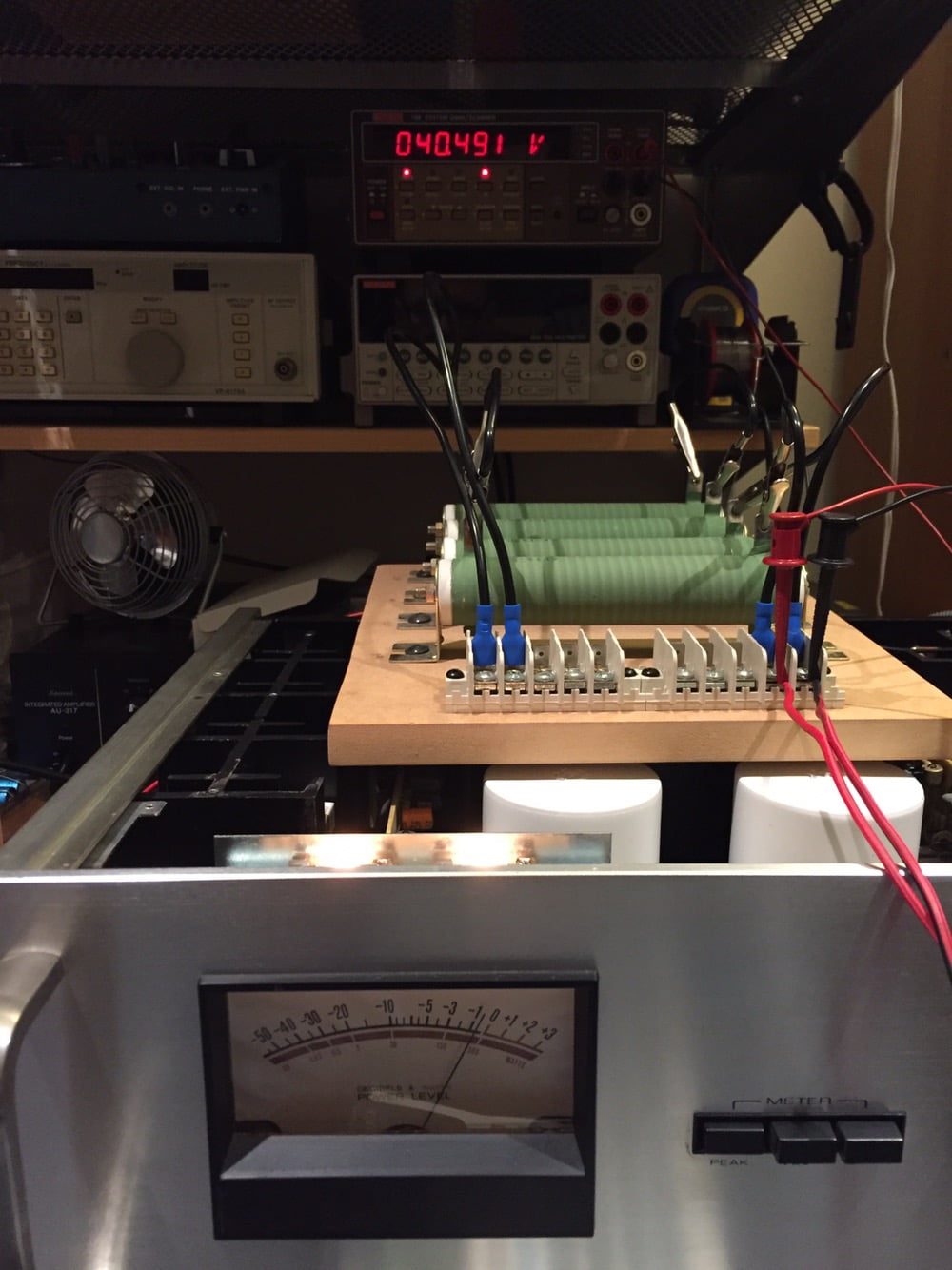
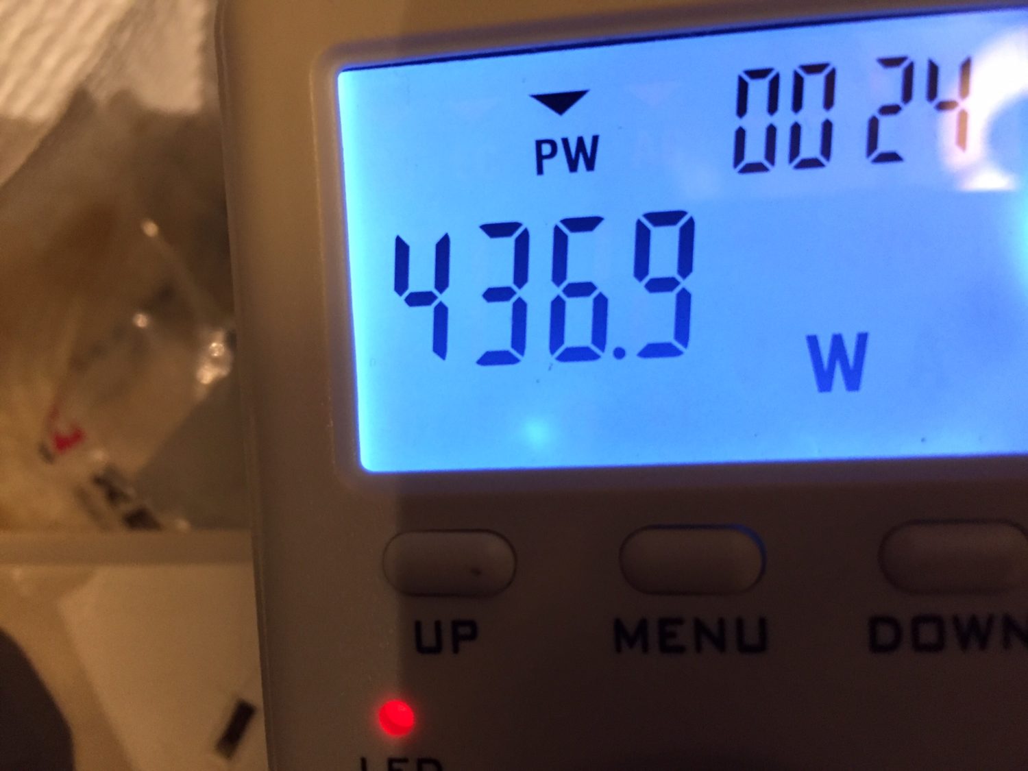
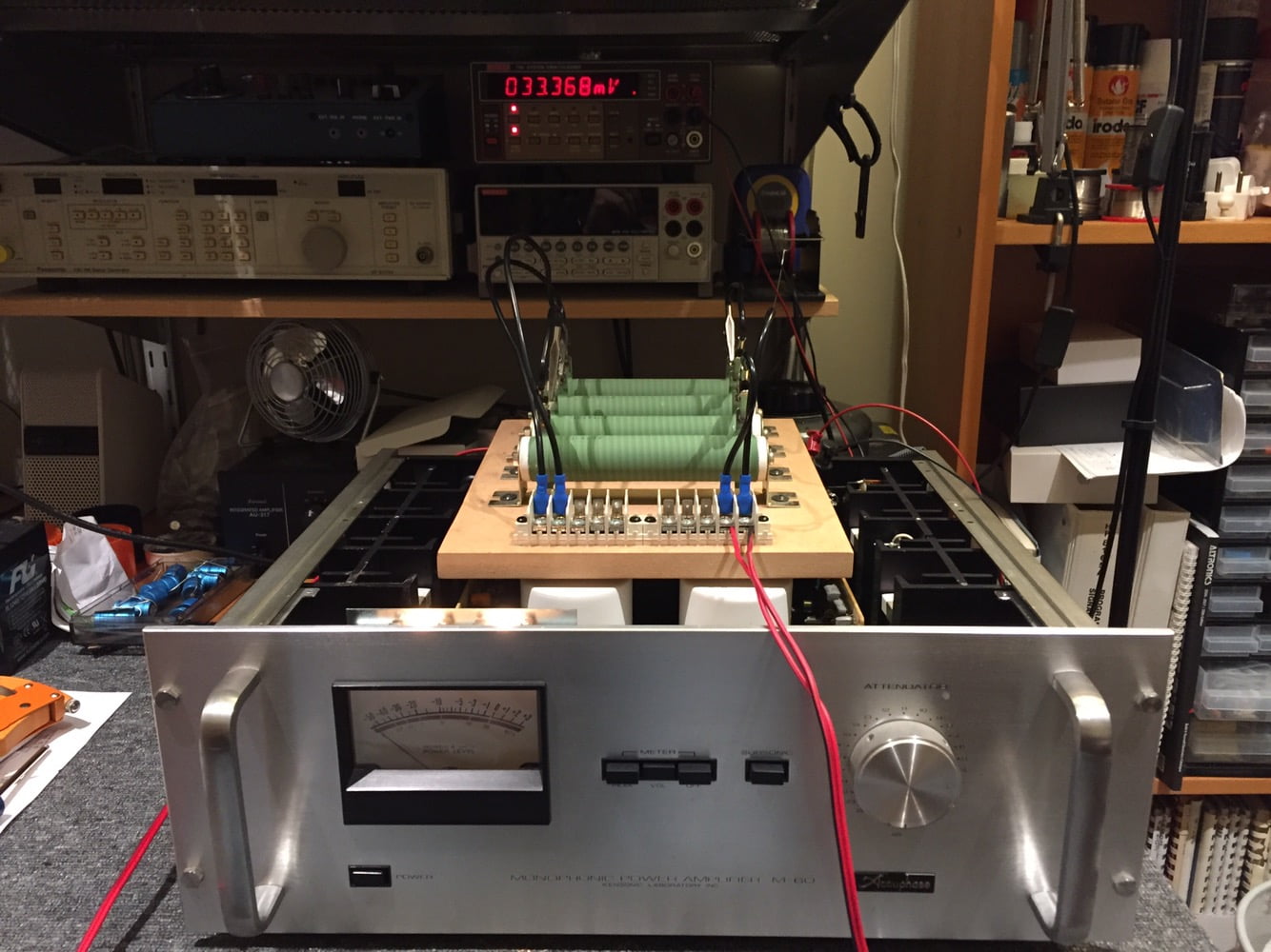
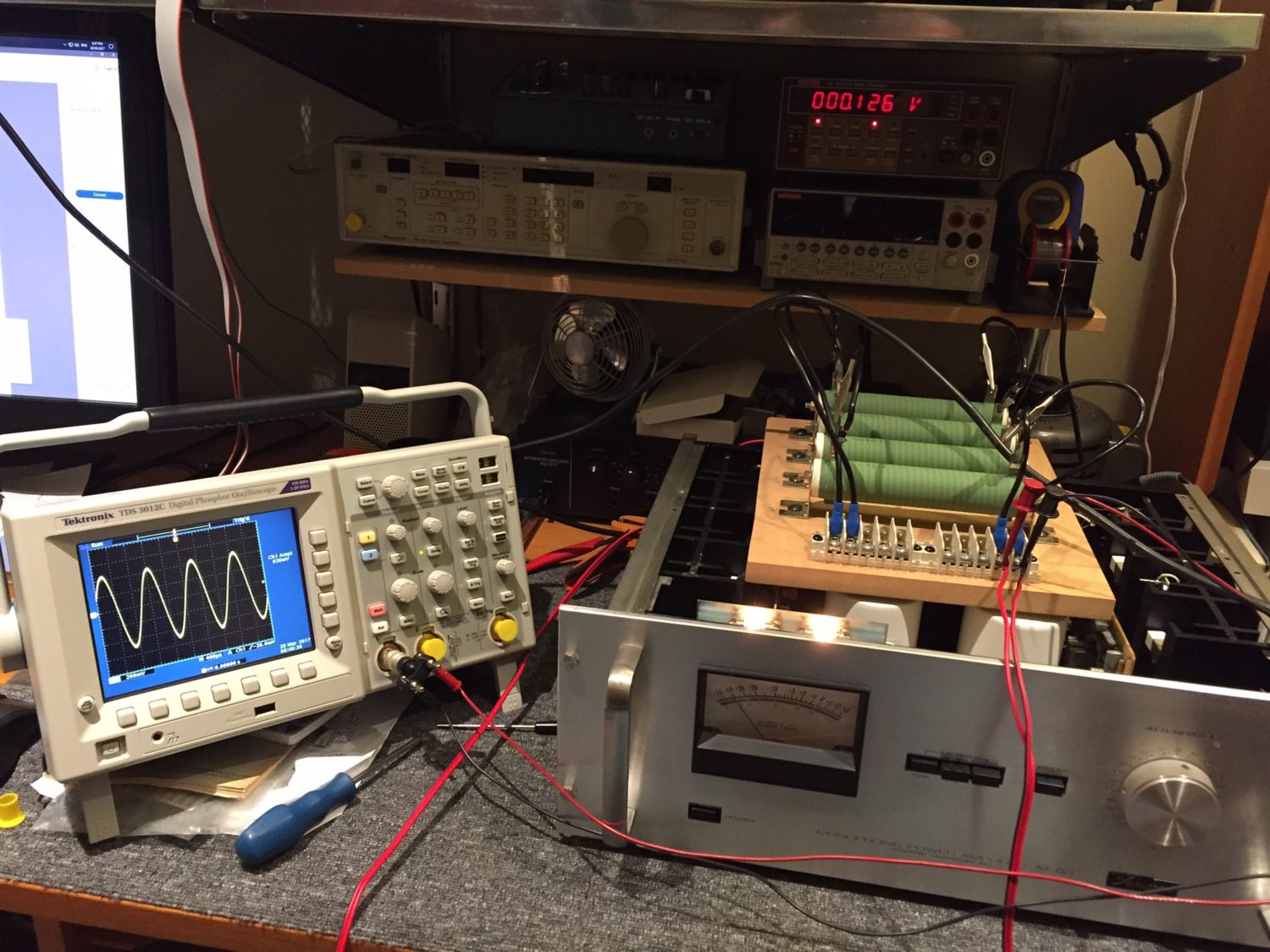
One of the things I enjoyed most was load testing these amplifiers. With amps this powerful, I could hear each 400 Watt load resistor ‘singing’ to the 1kHz test-tone! Of course, the best part was connecting these babies to speakers and hearing how great they sounded. Properly restored, they run stable, cool and without a hint of stress or harshness.
Handover
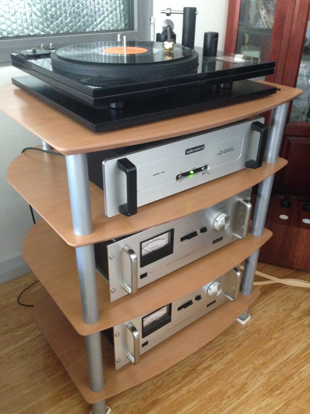
The last thing was to hand these gorgeous Accuphase M-60 power amplifiers back to their owner. Simon was shredded by the guy before me. I wanted him to be completely happy, and he was. He told me the amps sound incredible in his system, that they’ve never sounded better. Seeing the huge smile on his face when he collected them is the reason I love doing this!
Discover more from LiQUiD AUDiO
Subscribe to get the latest posts sent to your email.



Top job Mike! Reminds me of a mate of mine, ran the old Alberts HiFi in Fremantle many years ago. A pair of M100’s, a Michell GyroDec and a pair of Gales.. OMG pure ear candy ! …took a couple of decent blokes to shift those Amps as well
Cheers
Mal
Thanks Mal, this was a very involved job but very rewarding. Also a timely reminder of why many repairers out there need to stay away from equipment like this!
Wow! This is the most detailed post I’ve seen yet. I’m so happy you were able to save those wonderful amplifiers. The more I see on your site about electronics repair the more fascinated with it I become. Mike, I fear I may get sucked into learning some of the trade as a hobby once I retire…(assuming I can ever acquire some skill with a soldering iron)LOL! Could you elaborate on what electrical variables exist in premium caps as opposed to the cheap kind that the previous repair worker used?
Hi Tim, thanks and I’m glad you enjoyed the post. Lots of variables exist between electrolytic and other caps. The main properties to consider include ESR, impedance, ripple current rating, rated and working voltage, rated life@temp, leakage current, temperature rating, frequency response, dissipation factor (tan). Impedance, frequency response and resulting distortion are particularly important in audio gear. ESR and leakage current are important everywhere. There are lots of good articles out there on capacitors, perhaps some good bedside reading..?! I suggest articles by the manufacturers, Vishay / Roederstein have some excellent material out there to read, as do the others. Cheap caps have higher impedance, higher ESR, poorer frequency response, lower ripple current, lower rated lifetime, higher leakage current etc.
thats right doit once perfekt, why dont set the reistors in the same direktion that all the other on the drive board?
Thank you and yes, this is my philosophy with everything I do. You may not be aware that resistors are non-polarised components, so their orientation is not important in electronic terms. Having said that, you are mistaken, I purposely oriented the few resistors I replaced in the same direction as others nearby. The tolerance bands are at the left-hand end of the resistors in the images, and all are correctly oriented when referenced to their board designators. I’d suggest also that the attention to other details, like the power rating of the resistors I used, their composition and the way that I spaced them equally, up off the board is more important. Thanks again for reading!
Wonderful post Mike,
Do you ever work on vintage SAE amplifiers like Mark 3CM?
Are you able to work on components shipped from the United States
respectfully,
Byron Stutz 1-423 463 8936
Hi Byron, glad you enjoyed that post. I don’t work on a lot of SAE, but always happy to. The bigger issue is distance, I strongly discourage potential overseas customers from sending items like this as the risks and costs are high. I’m also fully booked at present which doesn’t help. Feel free to make contact more formally via the Contact page, we can chat better that way.
Good to see a proper restoration job done on this classic M60 amplifier. Shotgunning of electrolytic capacitors seems to be a common practice among some repairers. I can’t understand why a tech wouldn’t use an ESR meter to see if those ELNA electrolytic capacitors were still OK. Cheers Brian.
Thanks Brian!