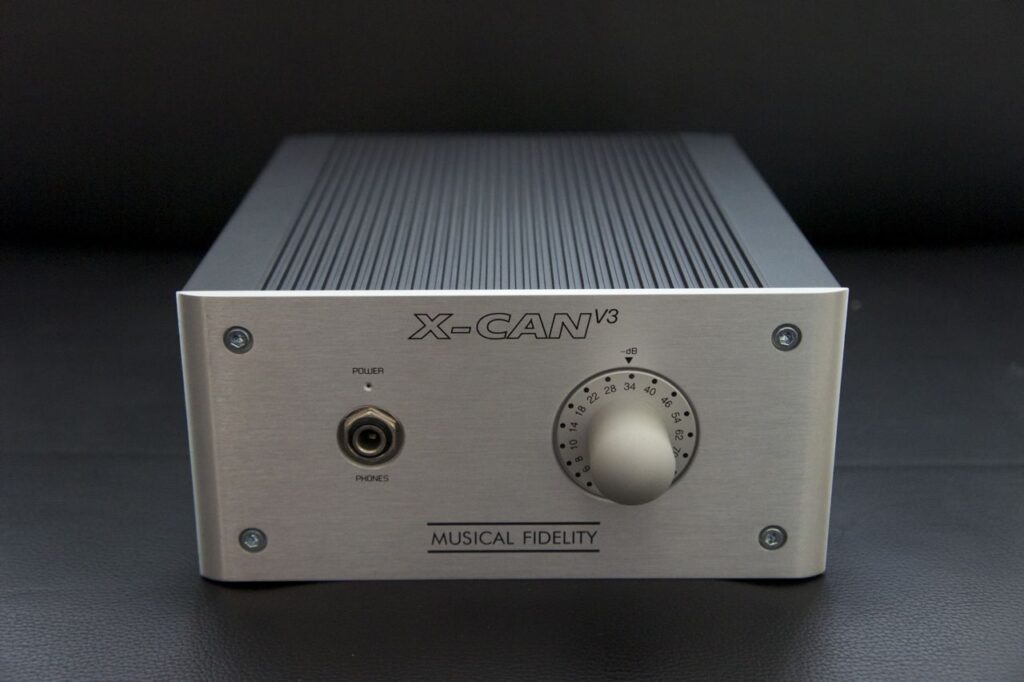
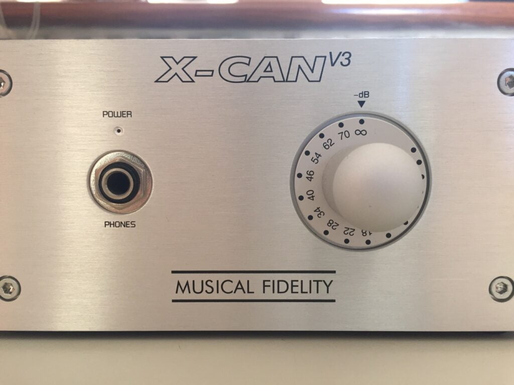
I recently modified a Musical Fidelity X-CAN V3 headphone amplifier. My goal was to see what sort of improvements I could make without spending too much cash.
The Musical Fidelity X-CAN V3 uses bipolar output devices, with a tube driver stage. The tube driver stage is a JAN (Joint Army/Navy) 6922 mil-spec dual-triode tube, per channel. These tubes run in class A and give the voltage gain necessary to drive a pair of BD139/BD140 bipolar transistors. The transistors provide the current to drive headphones.
The Philips 6922 tubes are mil-spec parts, rated for insane G-forces. Plenty of nonsense has been written about why you must change the 6922 tubes for ‘better’ ones. This is ill-informed, like so much of what is written in forums. These are premium parts, from the golden era of tube manufacture. There is not much you can replace them with that could be better!
Aims
My modifications to the MF X-CAN V3 focussed on improving the power supply and signal path. I met these aims relatively easily, by removing some components and substituting higher quality parts in key places.
Before starting, it’s worth taking some time to understand why these changes can benefit the X-CAN. A transformer feeds AC into the X-CAN. The rectification and DC filtering is done inside the headphone amp. The standard Jamicon capacitors supplied by Musical Fidelity are OK, but can easily be improved.
So why replace standard capacitors that don’t need replacement? Because we can get better performance from better parts. The factory caps are rated at 85 degrees and their ripple current specs, equivalent series resistance (ESR) and high-frequency performance are all average. Replacing the power supply capacitors with low-ESR Panasonic parts will lower power supply impedance, reduce ripple and give sonic benefits as a result.
There are other possible improvements. The X-CAN V3 chassis can accept the upgraded power supply called the X-PSU for example. This is actually just a larger transformer with 25VAC secondaries in a fancy box – you could make your own for peanuts.
Another thing you might try is to replace the standard rectifier diodes with some fast switching/soft recovery types like the MUR860. My experience is that these diodes refine the sound and add an air of subtlety.
Coupling Capacitors
Musical Fidelity seems to love putting large-value bipolar capacitors in the signal path of even their high-end equipment. There is a saying in audio electronics that “the best capacitor is no capacitor.” A signal path capacitor ALWAYS harms the signal, irrespective of type. This is because they are non-linear devices and therefore introduce distortion. This is especially true of electrolytic capacitors.
Manufacturers typically take a “belt and braces” approach to keeping equipment safe and reducing their own liability in the event of trouble. Having input and output coupling capacitors prevents DC voltages from appearing at the output and damaging equipment, headphones in this case. Most modern gear has input coupling capacitors. The X-CAN V3 doesn’t need them at both ends, so I deleted the input coupling caps and replaced the output caps with better spec’ed larger ones.
Let’s Modify!
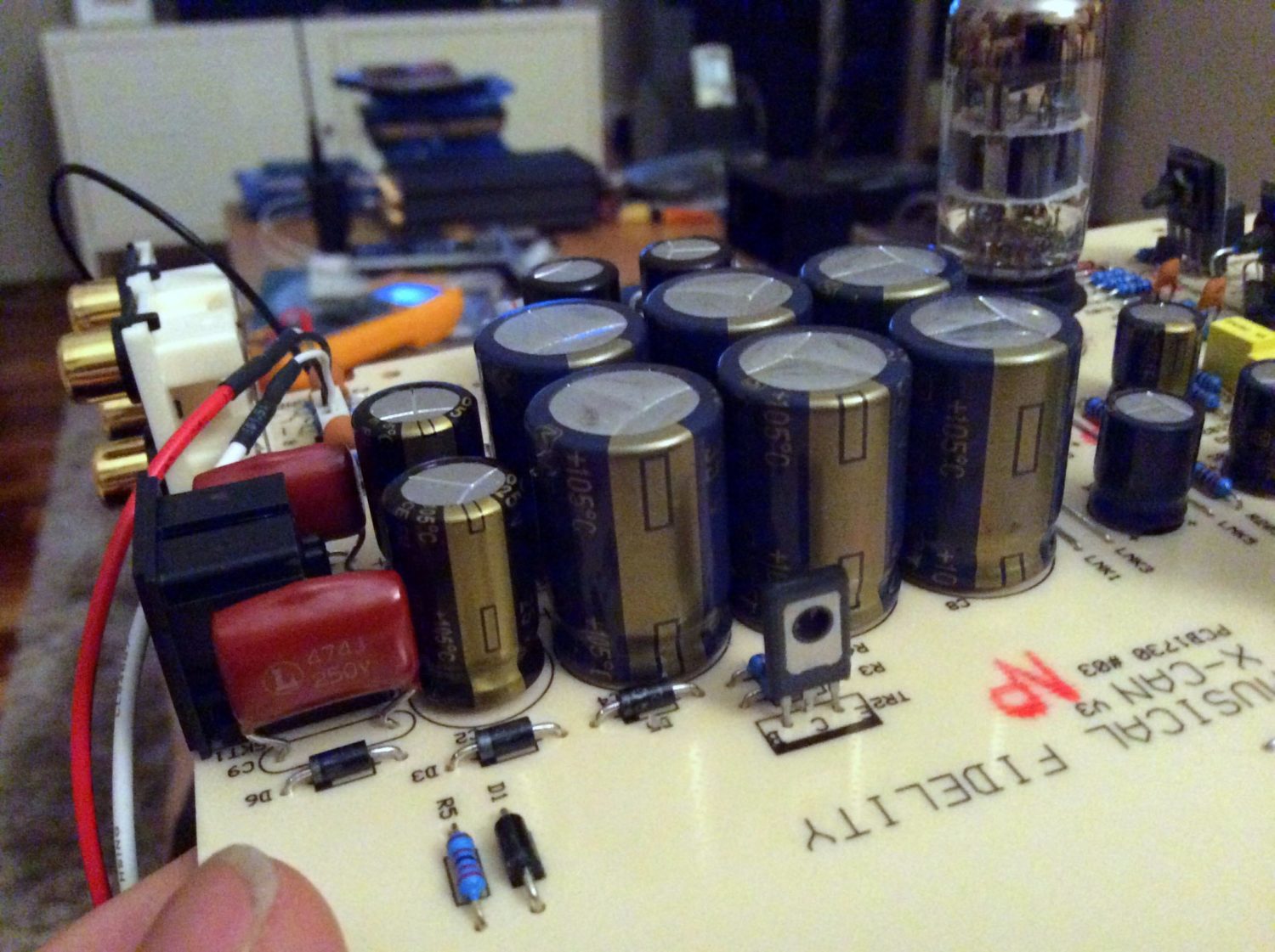
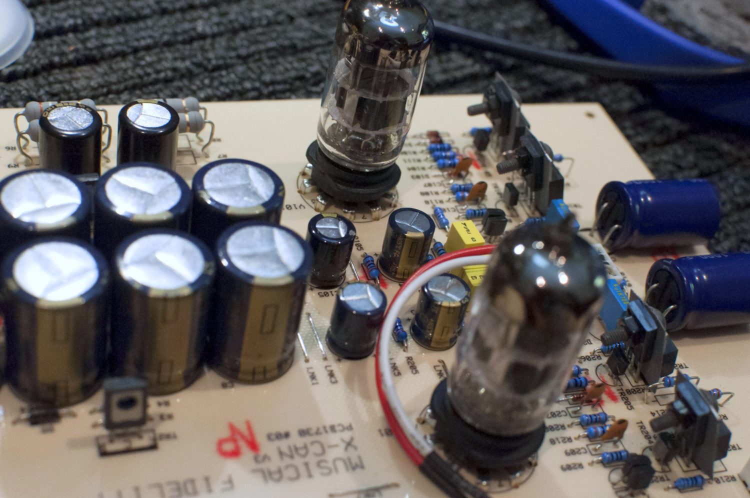
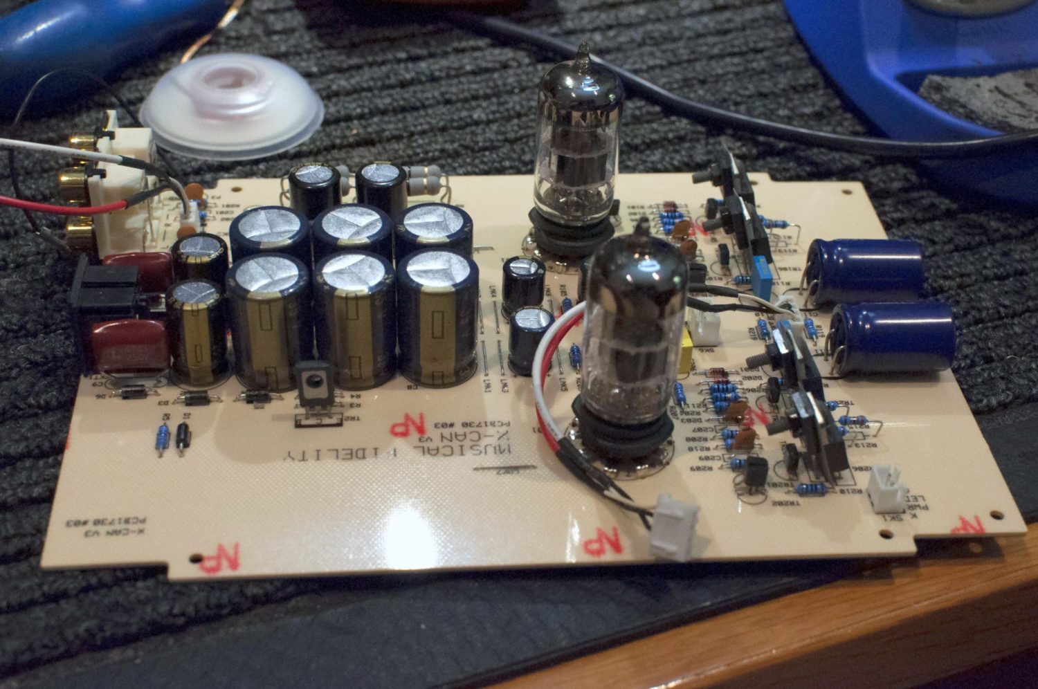
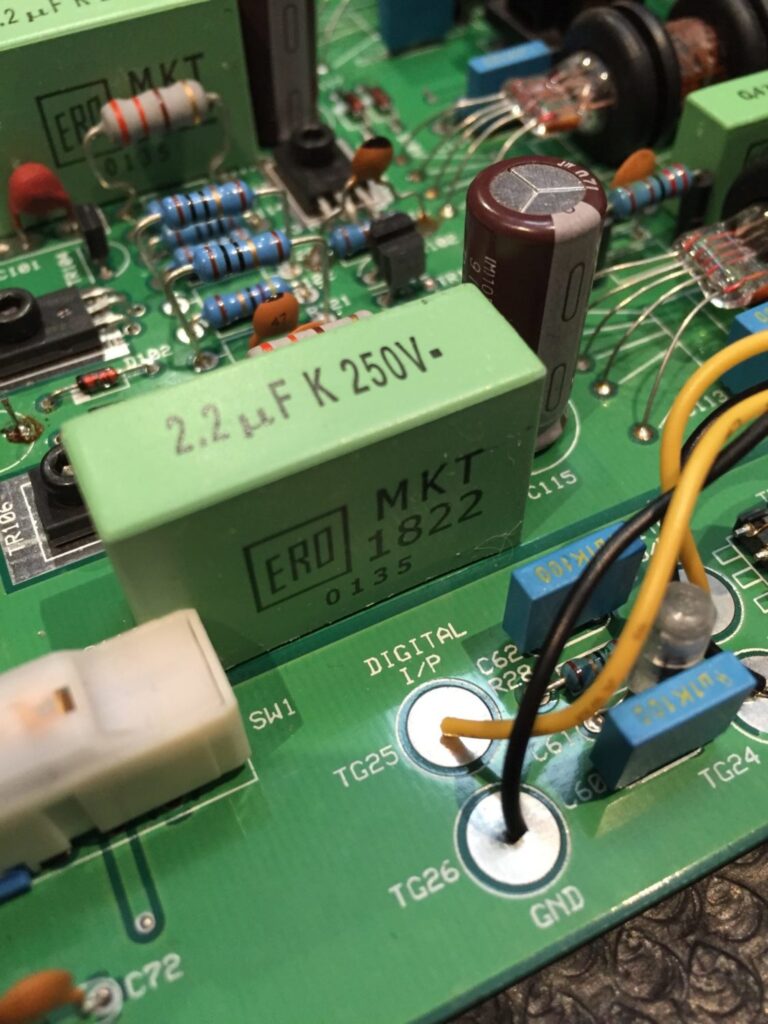
Alright, down to business. The modifications involve replacing every Jamicon cap with a Panasonic FM or FC similar. You can increase capacitance, there will be no penalty for doing so unless you go crazy, but standard values are fine.
Next, you want to remove the input coupling caps and replace them with wire links soldered to the board. The pics show each of these steps more clearly.
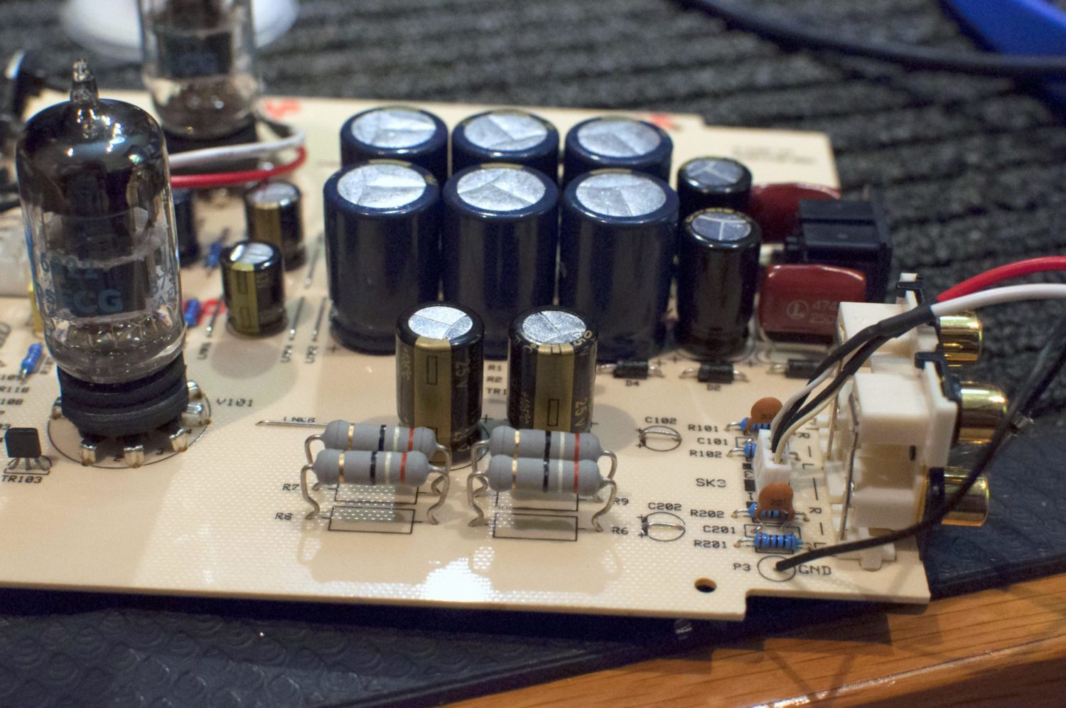
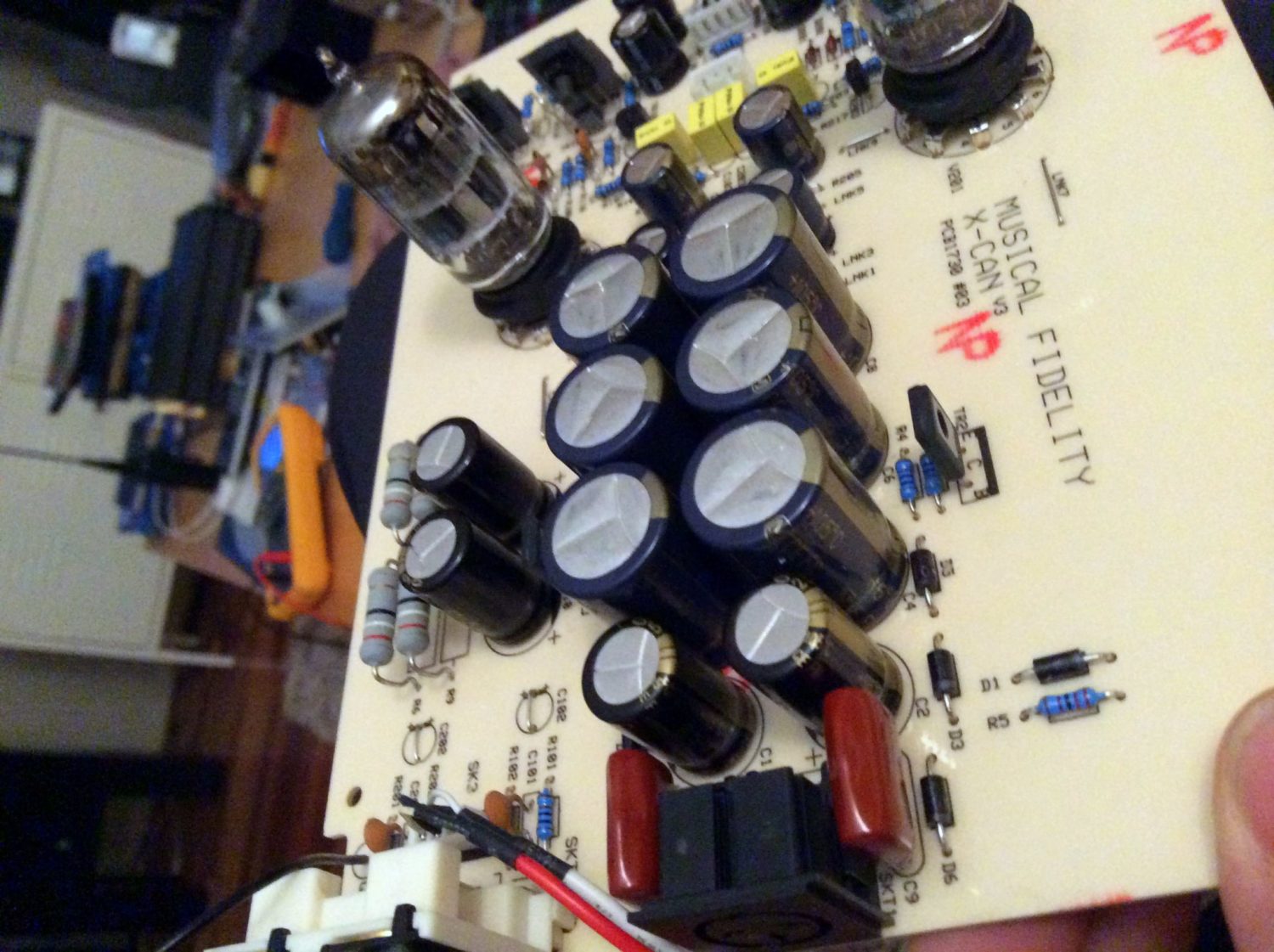
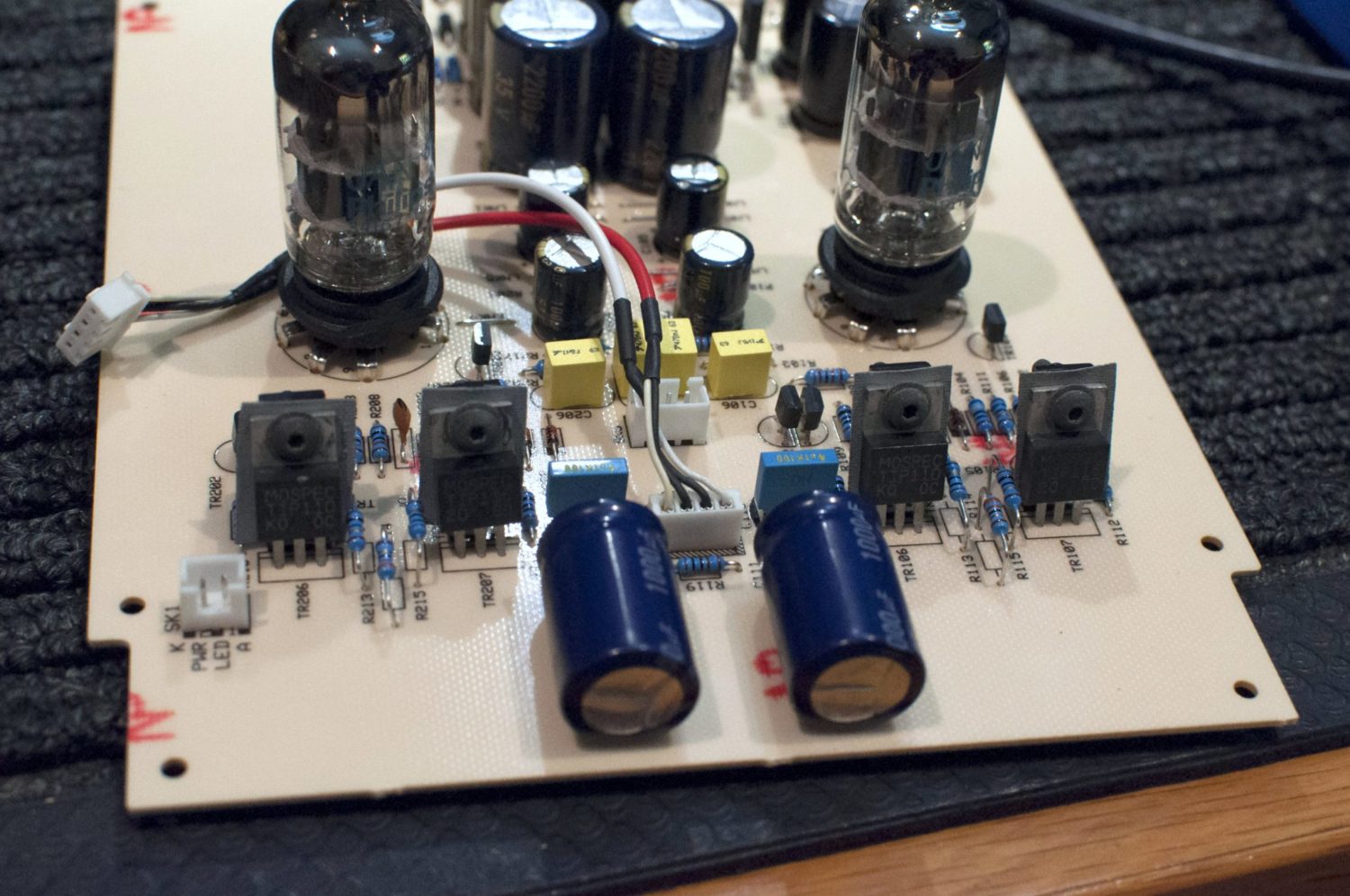
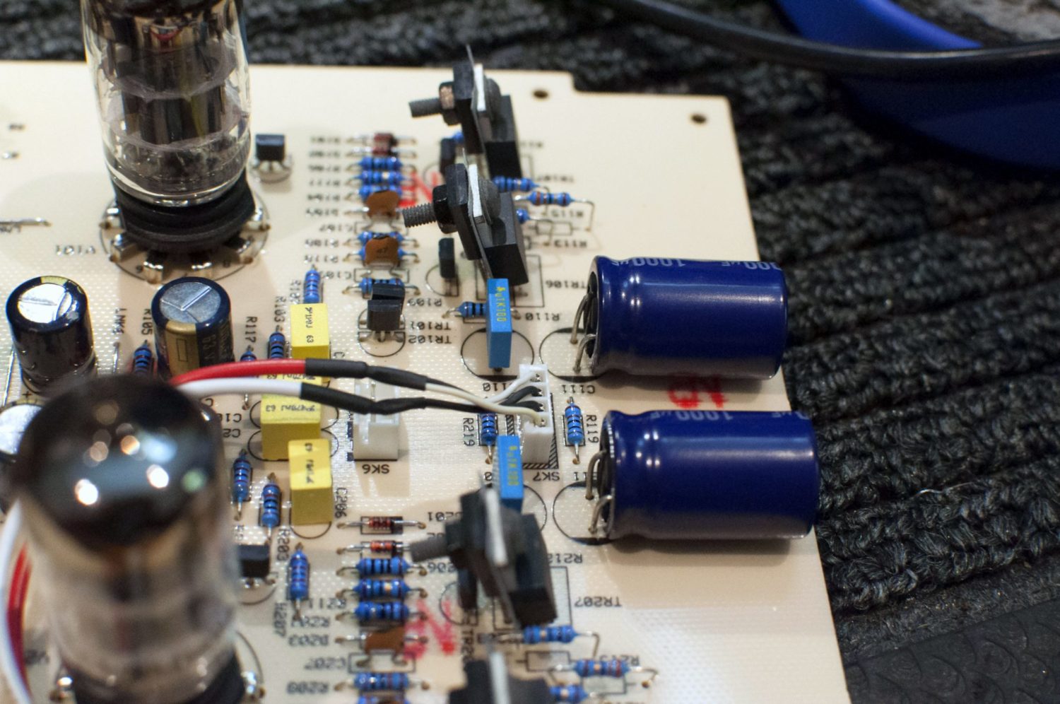
Finally, you need to remove the standard bipolar output coupling capacitors and replace them with higher-spec parts. There are two 470uF coupling capacitors per channel. I used one 1000uF capacitor per channel instead. The large value prevents rolling off the bass frequencies where they might be audible. This is not a DC amplifier, but the corner frequency is close to 0Hz with this large value.
Finishing Off
Make sure you fold the capacitors over so they are flat on the board. This is important or they foul the front panel controls. You will note that I have bypassed the electrolytic capacitors with mil-spec Siemens 0.1uF film caps. This improves high-frequency performance because it makes large capacitors behave as if they were much more expensive capacitors at high frequencies.
Discover more from LiQUiD AUDiO
Subscribe to get the latest posts sent to your email.


Looks exactly the same as the mods, Mike and I were doing over 10 years ago. But Mike took it even further.
Hi Benny, thanks for your comment, that’s great that you were doing something like this 10 years ago, though I’m not quite sure what your point is – people have been modifying gear in this way for decades!
Hi Mike, the 100nF (blue) film caps in parallel with the 1000uF output coupling caps are not necessary and are only “adding” more caps to the signal path. 2 x 1000uF non polar caps are all that you need. I tried bypassing the output caps many years ago but always found it sounded better without bypass caps. Perfectly good to bypass the power section electrolytics but, as you say, less is more in the signal path. Losing the four wirewound resistors makes a nice improvement, replacing them with one non inductive type really does perk things up: https://rockgrotto.proboards.com/thread/10847/safe-remove-wirewound-resistors-v3
Nice work Mike, another good resource for X-ponent lovers 🙂
Best regards,
Mike Grierson.
Hi Mike, thanks for the kind words and glad you enjoyed the site. In terms of bypassing electrolytics, there are excellent technical reasons for doing so as you probably know, related to the poor HF performance of aluminium electrolytic capacitors. I always recommend bypassing larger electrolytics, especially in critical signal areas. In cases where a capacitor must be used, like in this DC blocking role, we would always try to use the least damaging series capacitance, and this would be a large value cap, bypassed by a small value film cap of extremely high quality. This usually yields audible benefits, but not always, and I accept that it may not have for you in this instance. I haven’t tried the resistor mod but that sounds interesting and worth a look.