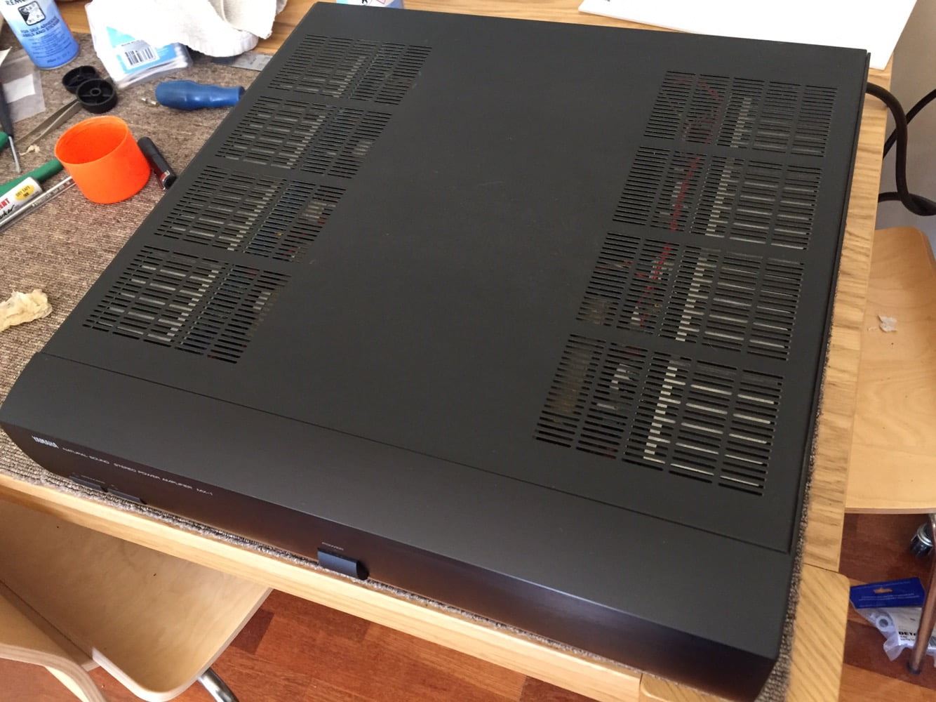
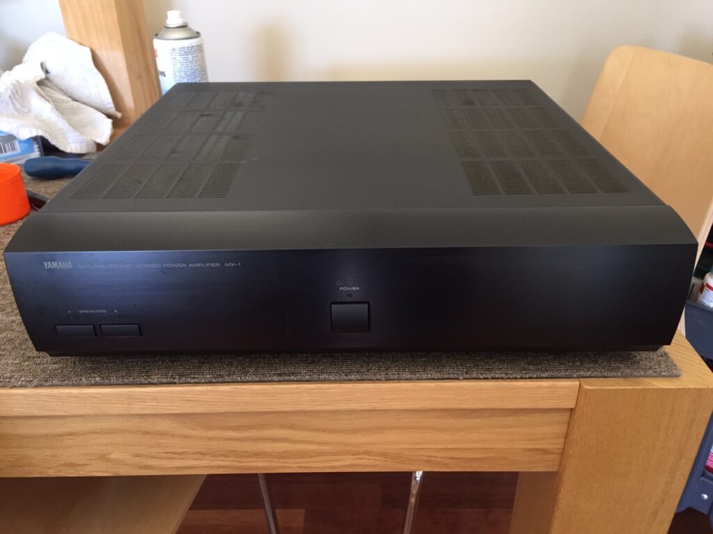
I’ve just repaired an amazing Yamaha MX-1 power amplifier. Read on for more about this stunning, heavyweight amplifier.
It’s fair to say that Yamaha, along with Sony, soldiered on with high-end consumer hi-fi gear for longer than many others and this beautiful Yamaha MX-1 power amplifier proves it.
The Yamaha MX-1 was the best and most expensive amplifier in the Yamaha line-up for 1993, and what a beast it is. I truly had to wrestle this thing around the workshop, it’s so heavy for its size, it feels like it’s made of lead!
As usual, I made a video about the repair, check it out:
Inside
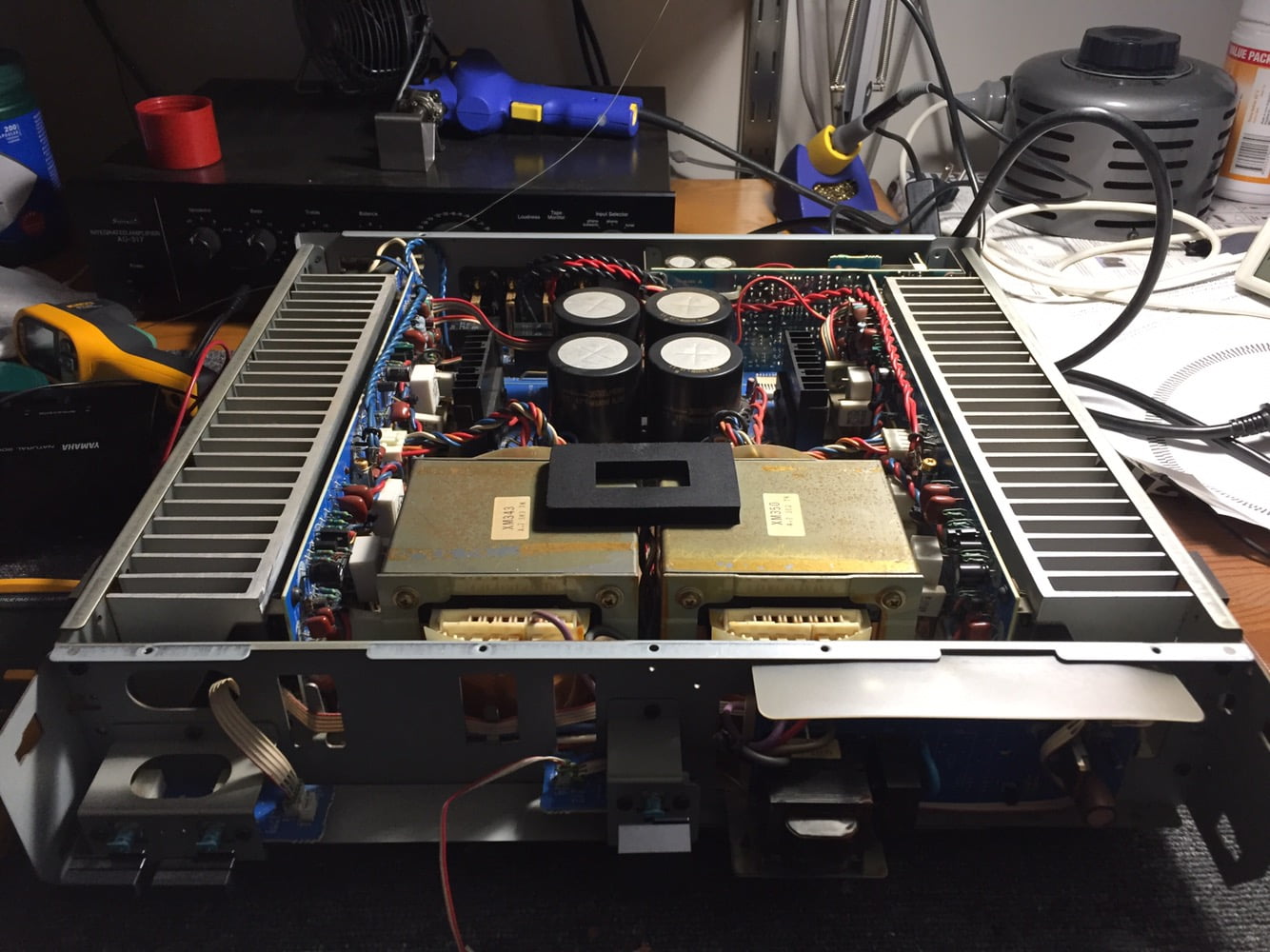
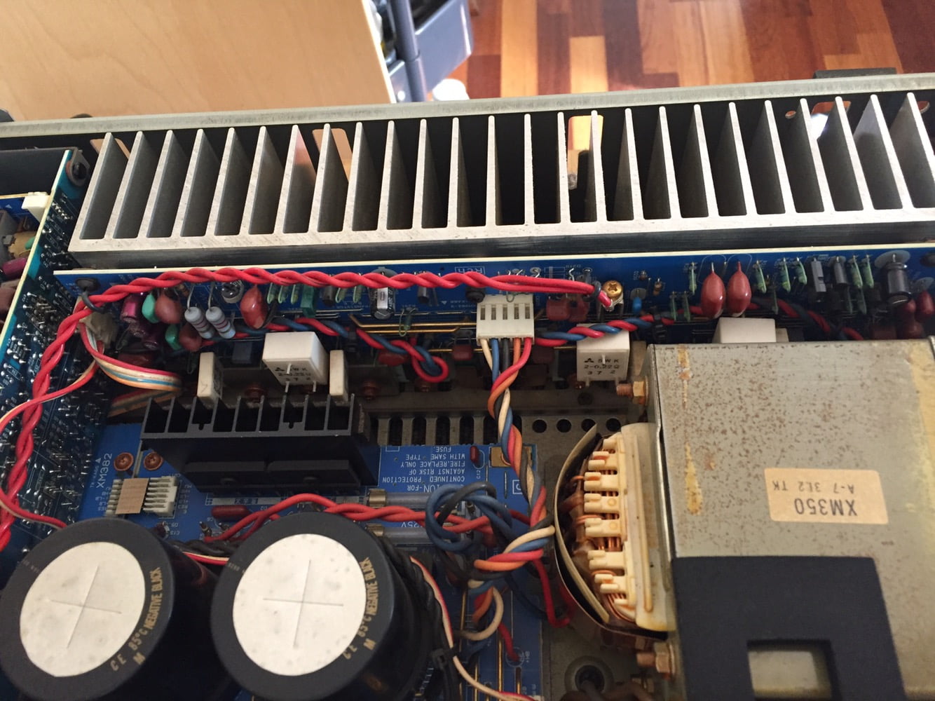
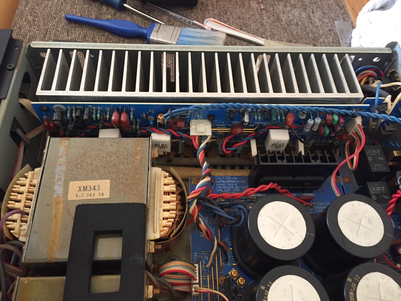
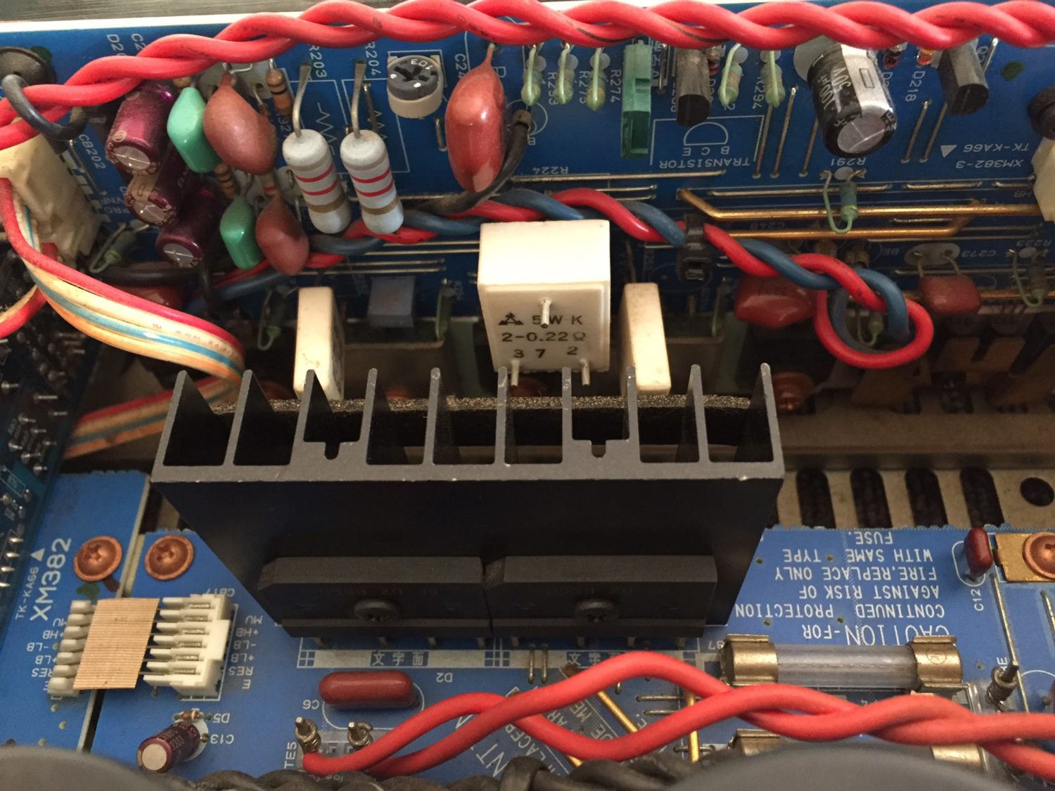
The Yamaha MX-1 is a very serious design and immensely heavy for its diminutive size. It appears initially to be a dual-mono design but upon closer examination, the filter capacitors are shared between the channels and two sets of power supply rails are derived from these, allowing ‘rail switching’, a feature designed to increase efficiency.
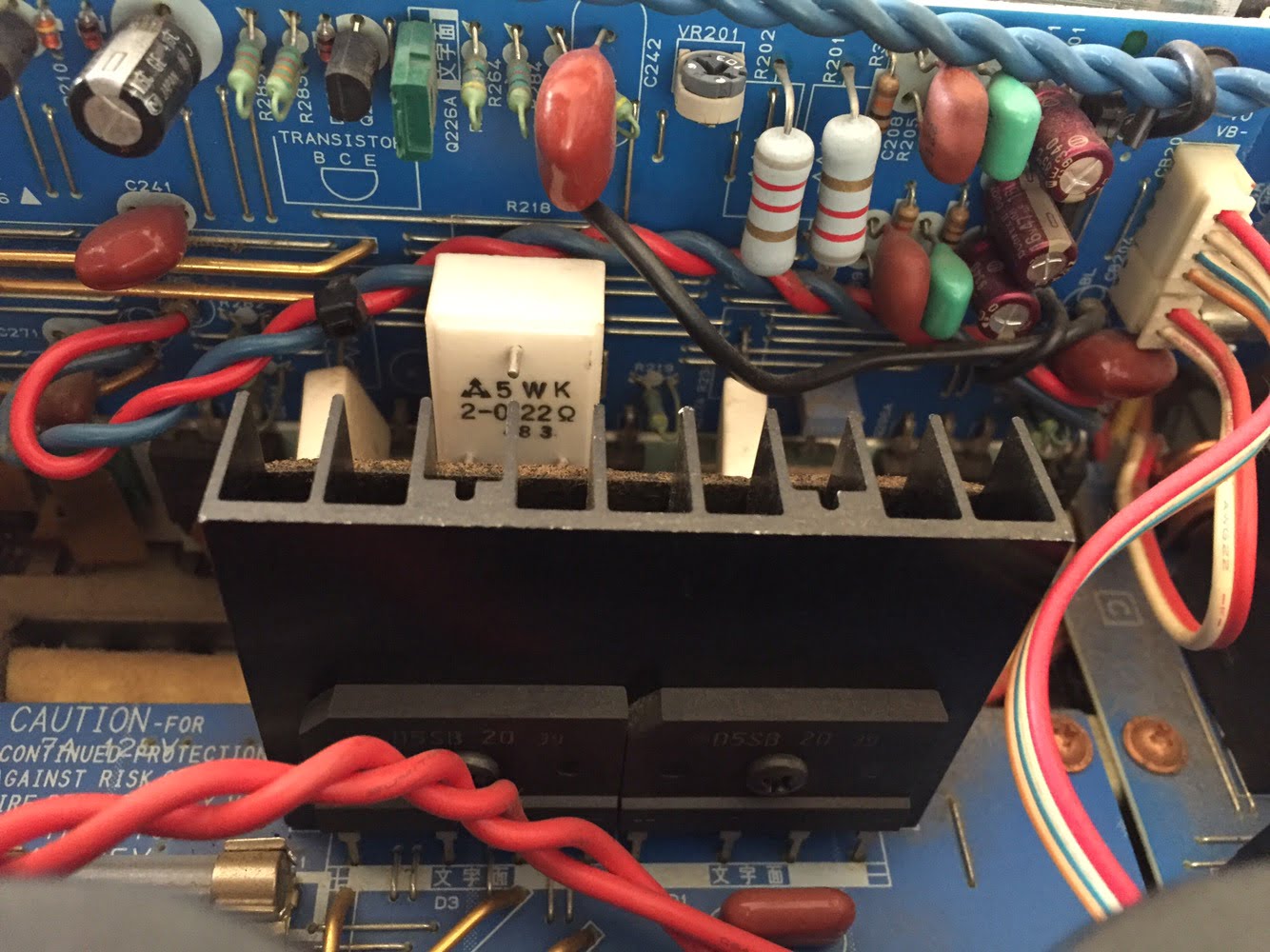
Besides that, the twin transformers, twin diode bridges per channel and separate heatsinks and driver boards almost qualify this as a dual-mono design, but not quite. The best and really only true dual-mono designs have two separate amplifiers in one box, including power supplies and even power cables, like this BAT VK-500 I repaired.
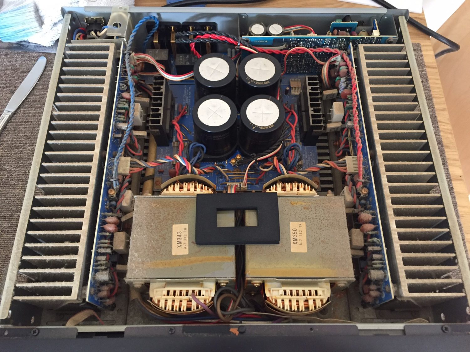
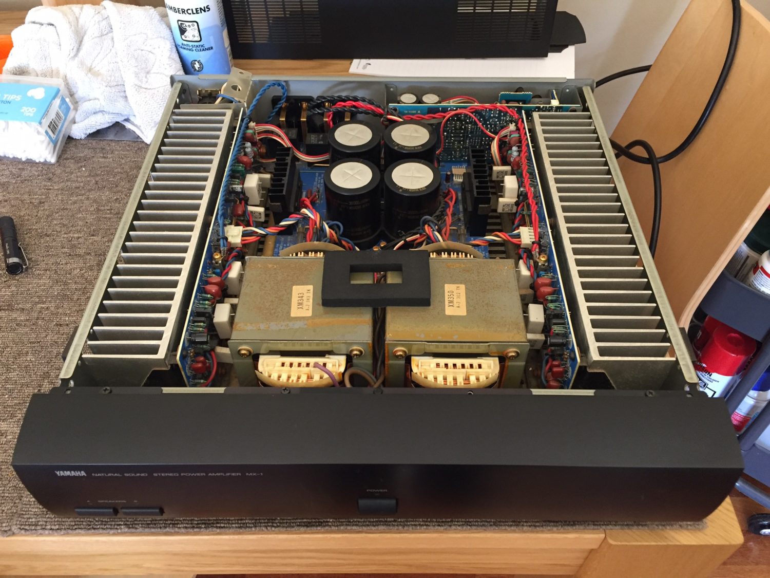
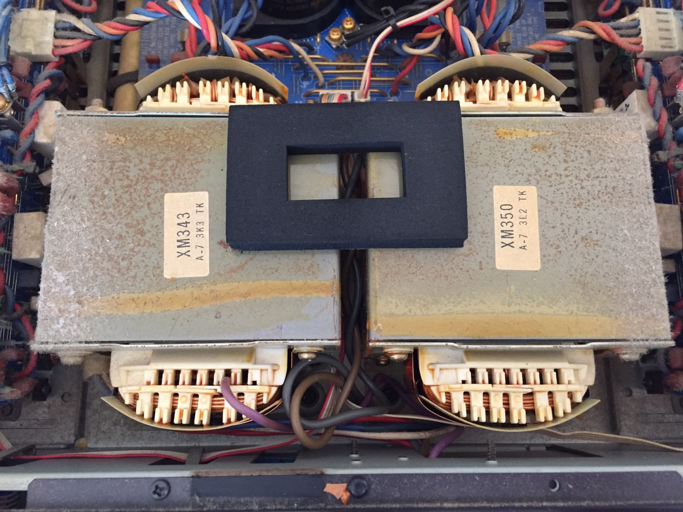
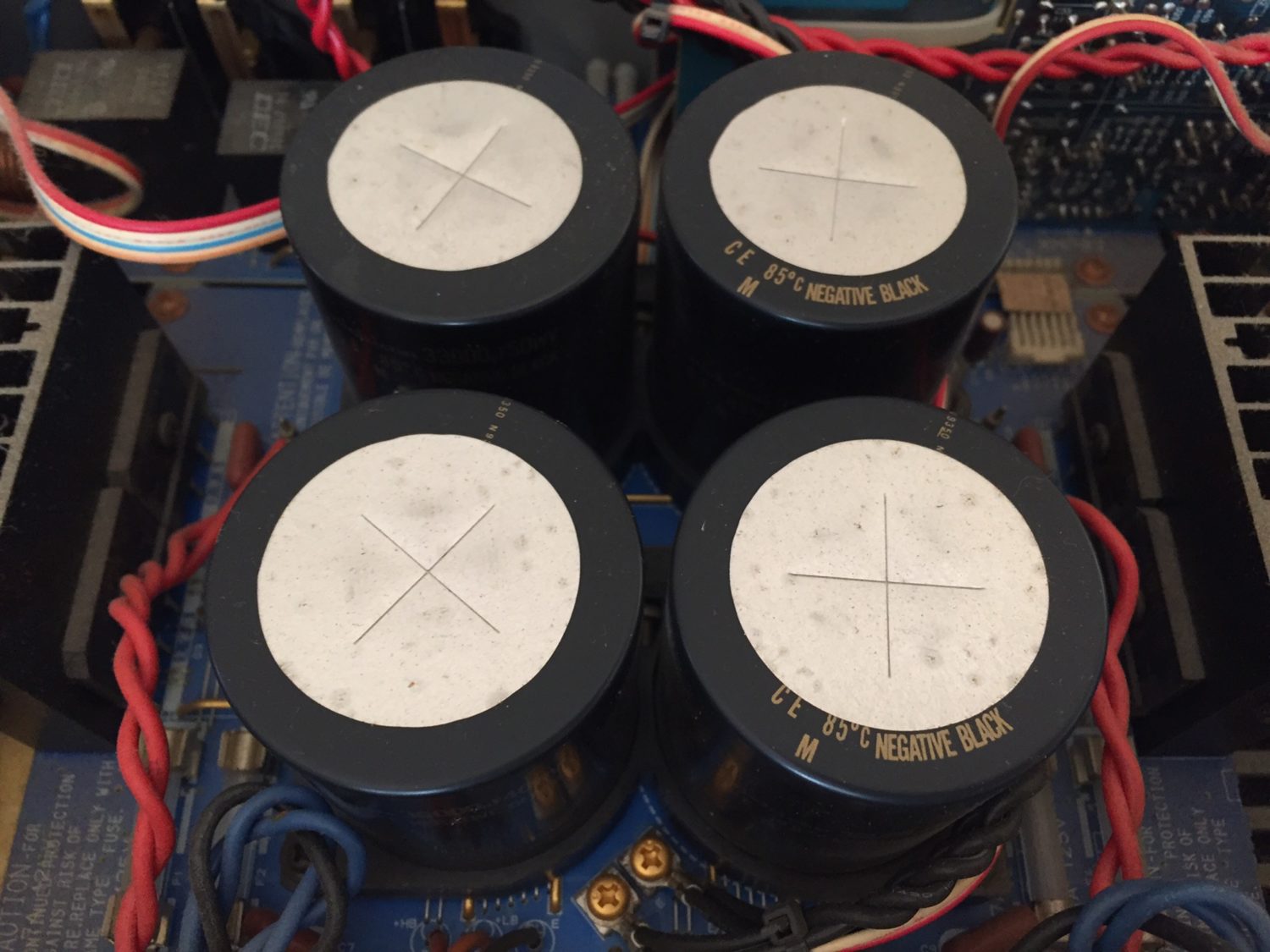
This is a beautifully built and very cleanly laid-out amplifier. The result is that it’s a breeze to work on. Like all well-engineered equipment, each area is easily accessible and each module is easy to remove. Modern gear is just not made this way. How much of what you buy today do you think will still be working 25 years from now…?
Yamaha MX-1 Specifications
As always, courtesy of HiFi Engine
Power output: 200 watts per channel into 8Ω (stereo)
Frequency response: 20Hz to 20kHz
Total harmonic distortion: 0.008%
Damping factor: 250
Input sensitivity: 1.46V
Signal-to-noise ratio: 125dB
Dimensions: 438 x 116 x 486mm
Weight: 24kg, good Lord this is a heavy thing…
Year: 1993
The Problem
The problem with this MX-1 was that the amp would turn on, but not really turn on. Let me explain. Push in the power switch and a red LED lights up. Cool, except that there were no voltages present anywhere that I could measure, except on the primary side of the main transformer.
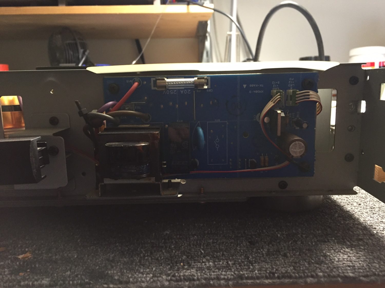
It took a little thinking time and looking at the schematic to realise that this thing has a soft or ‘remote start’ arrangement. This explains the very light power on button ‘feel’. This secondary power supply is behind the front panel.
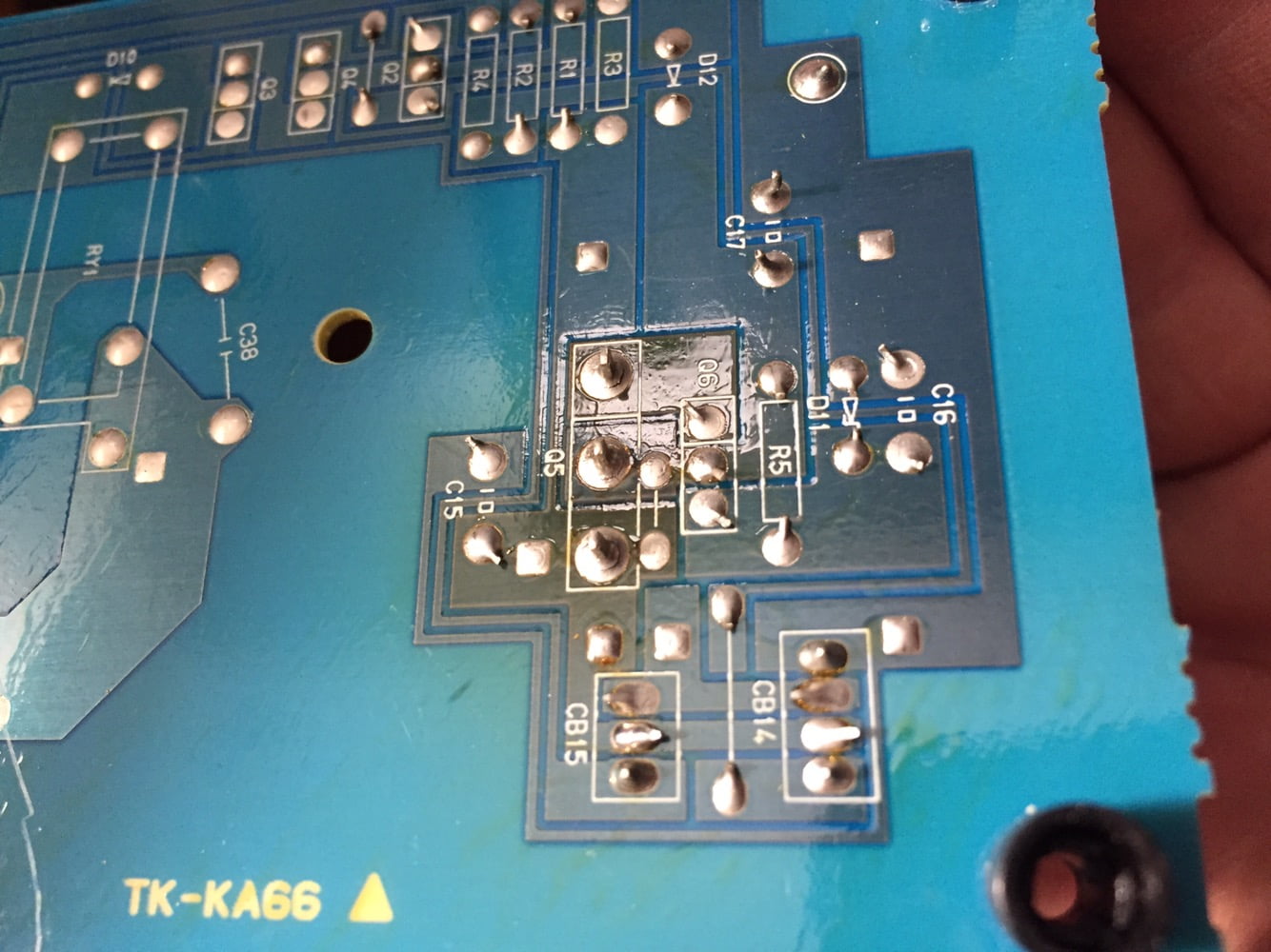
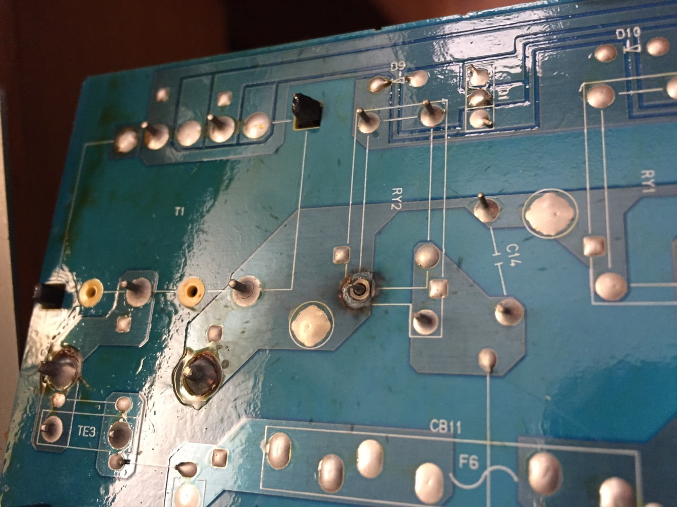
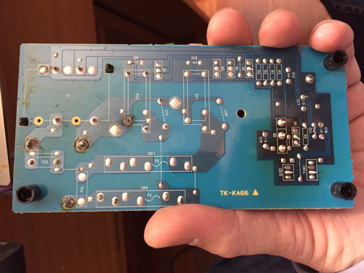
The board shows severe signs of solder joint erosion around all of the switching power transistor legs and one leg on the relay that it switches. The power transistor was completely disconnected from the circuit, so bad were the three dry joints. The eroded relay joint was so bad that all the solder around the leg was gone, along with the copper.
Repair
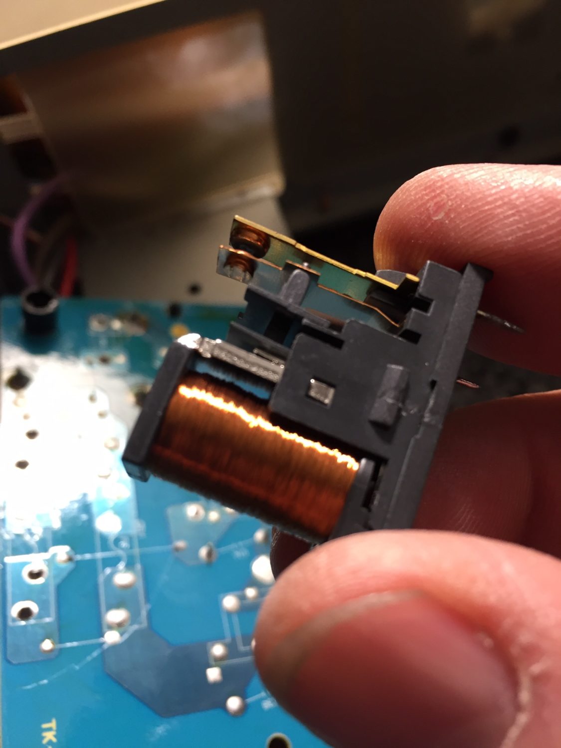
This part was straightforward. I remade the eroded relay joint by removing solder mask from adjacent copper to allow for a really large soldered area, making a nice, big joint. Then I refurbished the relay by opening it and cleaning the contacts. The new joint is electrically and thermally very sound, so this fault won’t occur again.
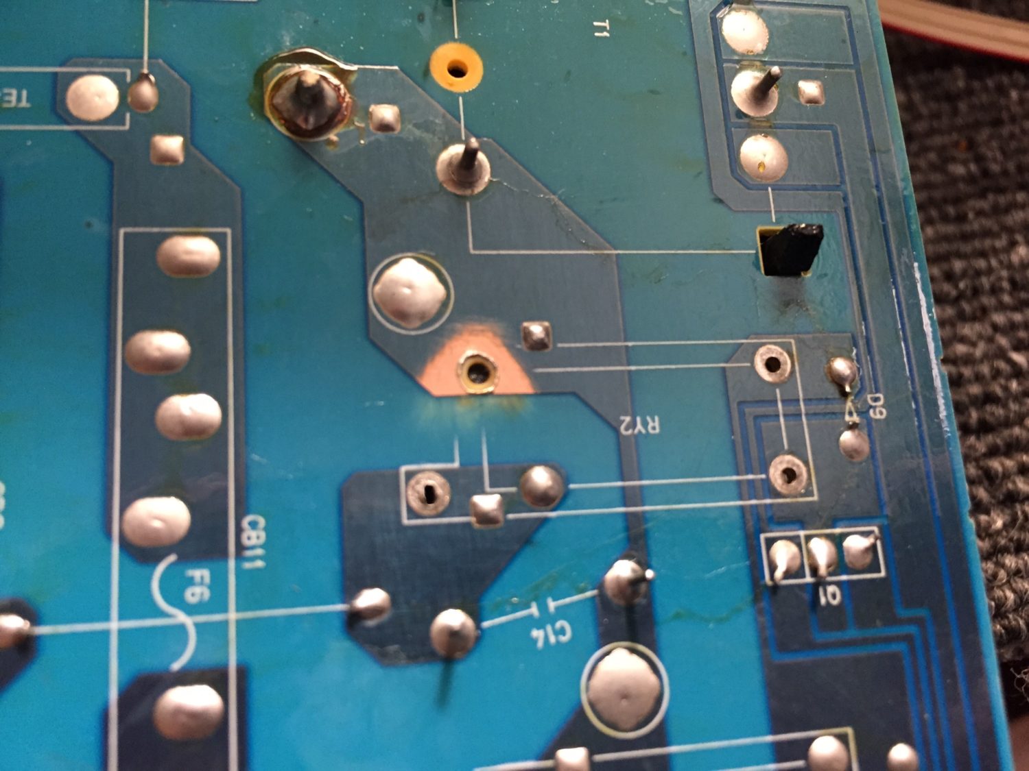
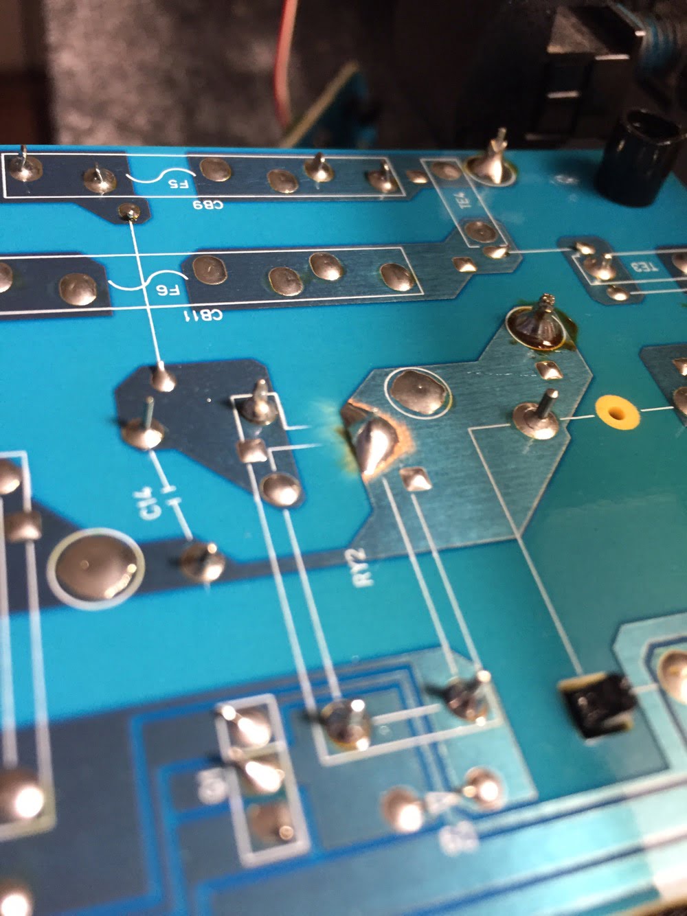
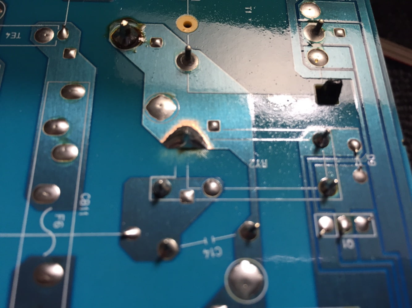
I resoldered the power transistor back in place and flux-cleaned the board. Out of curiosity, I quickly replaced the board without putting the amp back together and tested her – perfect! The amp powered up, no problem.
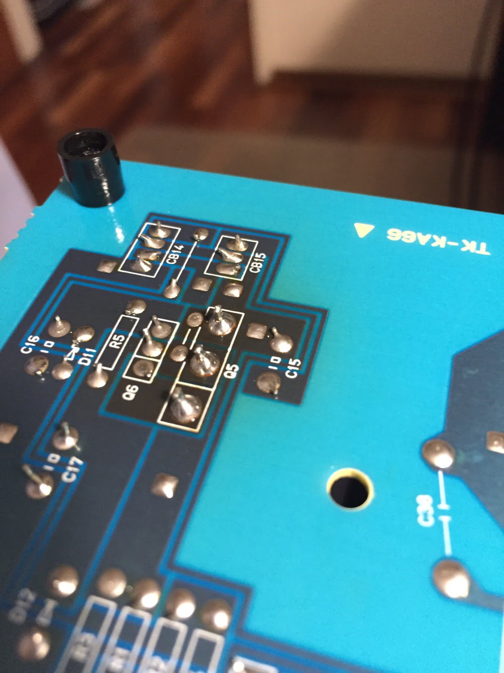
The last things to do were to reinstall the front facia, power the amp up and leave it on for a while to stabilise and then set the bias current. Both channels needed adjustment, so I set those to 14mV and then tested the amp with some music.
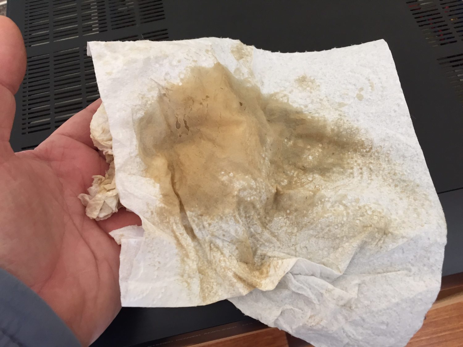
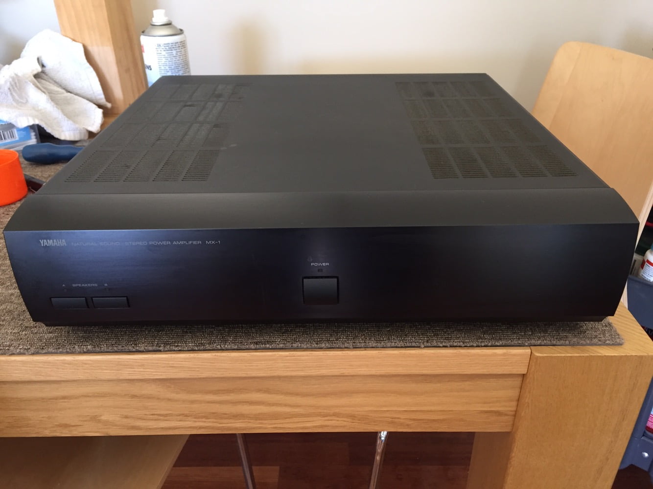
So, this was a very successful service and repair job, as usual. If you own a Yamaha MX-1, or any other beautiful Yamaha amplifier for that matter, don’t hesitate to get in touch regarding maintenance.
As always, thanks for visiting!
Discover more from LiQUiD AUDiO
Subscribe to get the latest posts sent to your email.


Beautiful amp and nice work Mike!
Hi Mike
Thank you for your report. I have two MX-1’s. One had exactly the same error.
I find that some transistors like the Q226A get very hot. Should I mount small heatsinks there to extend service life?
Best regards Ivan
(sorry google translator)
Hi Ivan, you’re welcome and yes you could, but just make sure that whatever you do is safe and well-implemented.
Thank you.
I’ve found that the transistors that get hot often have cold solder joints. They might be cooled by the circuit board.
Correct, excess heat causes gradual deterioration of the joint and evaporation of metal atoms, reducing thermal performance, accelerating the problem. This is why I make the repair the way I described in this article, it works well to resolve the issue.
Dear Mike, thank you very much! On my Mx-1 the transistor Q226A left channel and the Q232C right channel always get very hot. On my second MX-1 they are just a little warm. What could be broken? I can’t find the error. I really like the MX-1 and don’t want to give up. Kind regards Iven
Hi Iven, I don’t know, there may have been some iterative changes to parts values and/or the schematic which explain the higher operating current of the devices. Given the asymmetric thermals you’ve observed though, measurements will tell the story, especially around the devices in question regarding their biasing and power dissipation.
I have 2 of these in need of repair. Would you be interested in fixing them?
Hi Jeff, thanks for getting in touch and yes I’d be very happy to look at your MX-1 power amps for you. The clincher will be whether you are a Perth local, otherwise its probably not viable. Regards, Mike.
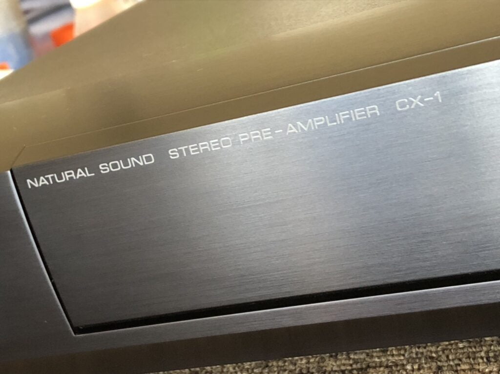
I am scouring the internet trying to figure out what class of amp this is. I have the original manual for it but it does not specify what amp class it is. I doubt it’s class D, probably class A. I have one of these which I bought new in 93 and it is still working fine and without a scratch on it. I also have the matching CX-1 preamp. Please help!
Hi, it’s a regular class AB amp, like 99% of other solid state amplifiers from this era. Much better than class D which was introduced as yet another way to reduce costs. You are very lucky to have a pair of these!
I have one but i can undecover, can someone tell me how please
Hi Jesus, I’m sorry but your question is unclear. What exactly would you like to know?
Mike I have same issues and I see no issues as you found on the board. The unit has not been plugged in for id say at least 5 years and its been properly stored in its original box
No problem, I suggest this is a good example of a unit that needs to come in for testing, diagnosis and repair. If you are local to Perth, you are most welcome to bring her in.
What would you recommend to replace Main filter caps? Only I can think of is Mundorf M-Lytic, but it’s like $500 for the 4 caps. Wonder if it’s even worth!
Hi Darlig, lots of options there besides Mundorf, some that would be better, but why do you need to replace them? Have they been carefully tested? Really good main filters like say RIFA/Kemet will make a difference for sure, but they are expensive as you say.
Can you please recommend the re-cap kit for the MX-1?
Hi Taylor, I’ll provide some additional observations you might find useful. As I mentioned, I don’t use or recommend kits for many reasons, but for someone working without parts to hand or the knowledge to help choose and order them, a kit may be an option. From a specialist’s perspective, the bigger questions are: does that person have the knowledge, skills and tools necessary to do the work well and what caused them to look for a kit in the first place? If there are issues, it’s worth addressing those directly. Shotgun cap replacement introduces many potential points of failure and rarely solves most faults. If you are looking to improve performance, capacitors can definitely help, but they must be carefully chosen and installed to avoid board damage and introducing other problems.
What re-cap kit beside the 4 Main cap for the MX-1 do you recommend? Thank you!
Hi Taylor, thanks for your enquiry. I don’t recommend any ‘kits’ as such, it’s better to replace parts as needed, based on testing and measurement, with the right parts for the job and budget. This is done case by case and in terms of what I do, with parts from stock. Let me know if you have any other questions.
Both MX-1 and MX-2 are fantastic amps. The sound is nice, warm and delicate. Perfectly capable of driving “difficult” speakers like Dynaudio. I picked them both while they were still cheap, however as the time goes, I see more and more of their kind turn into e-waste due to the inevitable IC201 failure. A custom-made, obsolete IC at the heart of the amplifier. 🙁
Great work on restoring the MX-1 and the owner is one lucky guy!
Hi Nikolay, thanks, glad you enjoyed the article and yes they are very nice amplifiers, especially the MX-1! Most regular consumer speakers will be no problem for this old girl. I’ve worked on many Yamaha amps and have rarely seen a BA3122N fail. Maybe I’ve been lucky, some fail no doubt, but I suspect some amplifiers are incorrectly diagnosed by people who stumble across forum posts about this issue and aren’t able to correctly diagnose the fault. Anyway, yes the owner is a very lucky guy!
Hi Mike, Just one thing … the MX-1 is not a dual-mono design. Take a look at the schematc and you’ll see that, although the transformers each serve their own pairs of rectifier bridges, the resulting +75/-75(HB) and +33/-33(LB) supplies for the output stages (which are dual voltage class G) share main capacitors wired in series. I do love this amp. John
Hi John, I’m glad you enjoyed the article and thanks for pointing this out. I didn’t say the amplifier was a dual mono design in the article, but I see that I wrote “dual mono transformers”, which is ambiguous and needs rewording. The main filters are indeed shared, with rail switching to increase efficiency, something I will clarify in the article. Apart from the shared main filters, everything is dual mono, but the distinction is worth making and rules it out as a true dual mono design. These are certainly a favourite of mine to work on!
Hi, maybe a difficult question to answer so just an opinion would be appreciated. I have an opportunity to buy a CX-1 & MX-1 in 8/10 condition for $1000 AUD. For that price would you say there are ‘better’ options or would it be hard to beat if I’m after a system that offers a clean neutral sound. Thanks. Ps…. Great site.
Hi Guy and thanks for your question. We have an advisory service specifically for digging into these sorts of queries and accessible via the contact page. Regarding price though, for those two pieces, if working well, it’s crazy cheap!
Great, thank you, will look at the contact page.