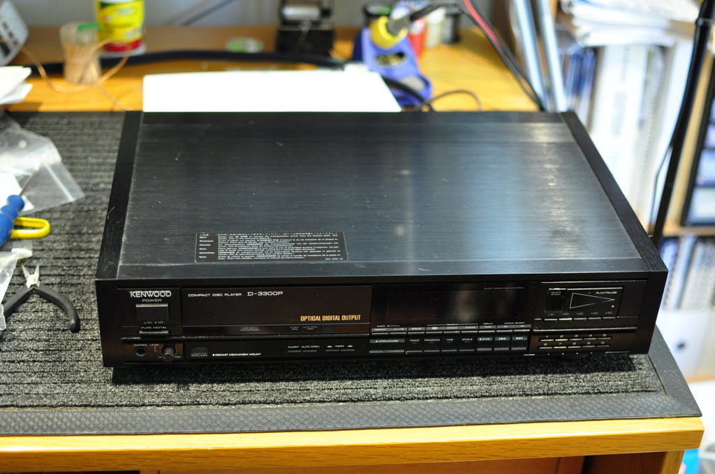
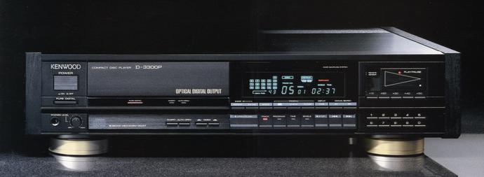
I’ve just serviced two gorgeous Kenwood D-3300P CD players for a customer of mine. He loves his classic audio gear and owns three of these beautiful CD players.
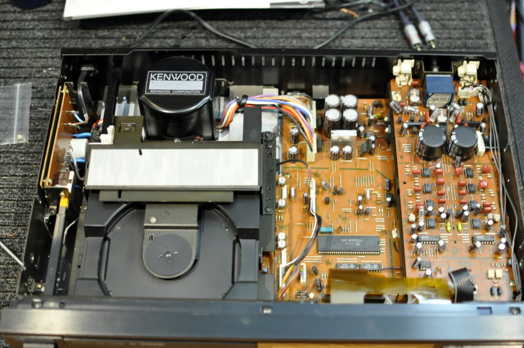
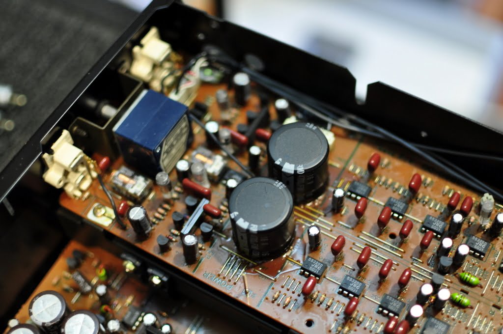
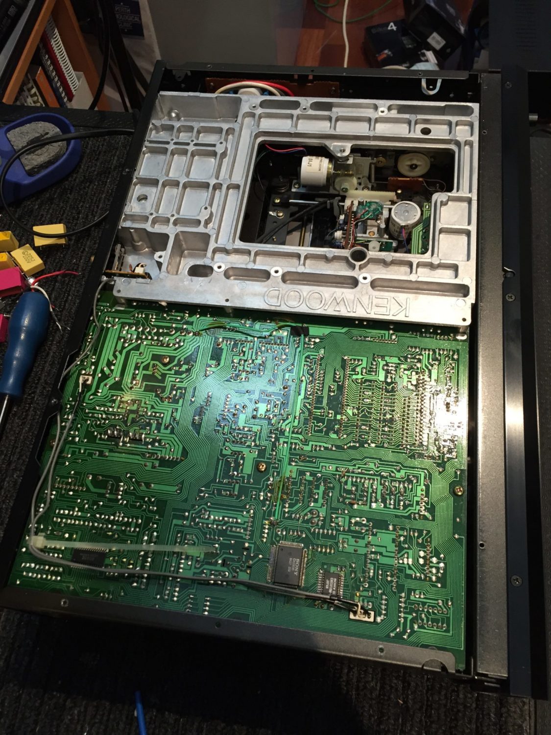
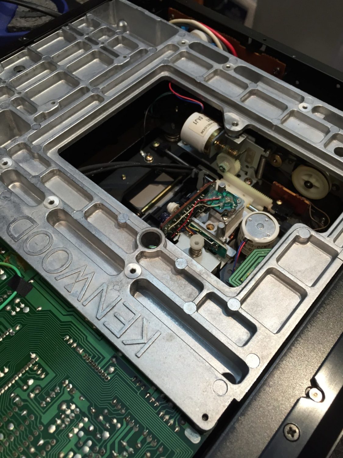
The Kenwood D-3300P CD player dates to 1986 and is a superbly built component. In fact, this unit is built from such quality hardware and components, that it would cost way too much to make now. The die-cast sub-chassis, for example, could never be included in players these days, short of 10+K Accuphase.
The D-3300P was the best player Kenwood knew how to make at the time. It weighed in at just under 11 kg, ridiculous for a CD player now. Much of the weight comes from the massive bottom panel and die-cast aluminium sub-chassis. Add gorgeous real wood cheeks and the large transformer and you can see where the weight comes from.
Architecture
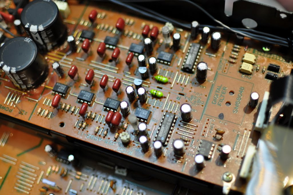
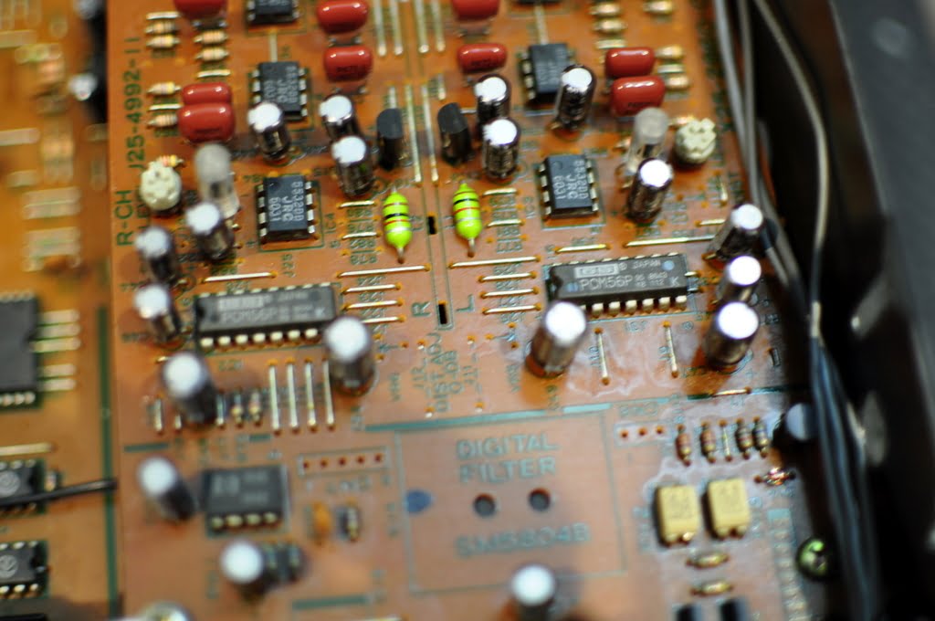
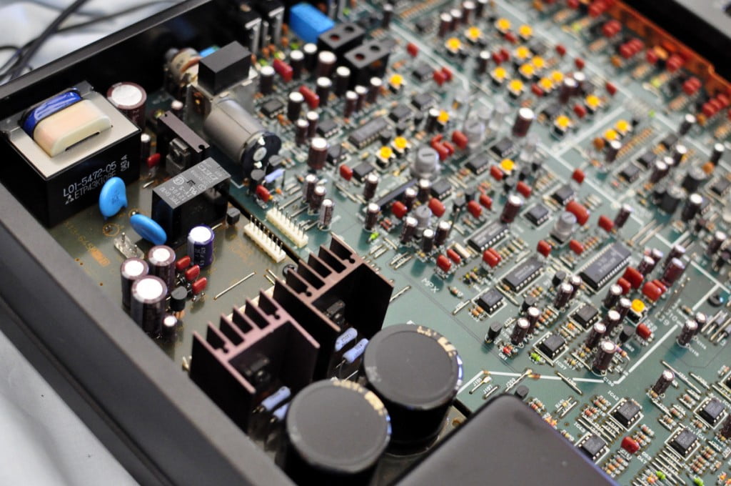
It is worth mentioning a little about the digital and analog circuitry of the Kenwood D-3300P. The player features the Burr-Brown PCM56P DAC chip – two, in fact, one per channel. This chip is a multi-bit as opposed to bitstream DAC. As such, it has the classic multi-bit sound that so many people love.
The chips were very expensive to manufacture and this is partly what drove the development of bitstream DACs. The PCM56P used precision, highly temperature-stable resistors in the resistive ladder output. All were laser-trimmed during manufacture to maximize the linearity of signals down near digital zero. The chips themselves were also trimmed, to null out the zero-crossing error and reduce distortion.
Burr-Brown claimed a 15-bit tonal resolution from this chip and the chip itself is the precursor to the very highly regarded and perhaps ultimate Burr-Brown chips, the legendary PCM63 and PCM1704K.
Kenwood D-3300P Specifications
Adapted from Audio Database
| Type | CD player |
| Reading method | Non-contact optical reading |
| laser | GaAlAs, λ=780nm |
| Number of rotations | About 200 rpm-500 rpm (CLV) |
| Error correction method | Cross interleaved Reed Solomon code |
| Number of channels | 2-channel stereo |
| Frequency characteristics (EIAJ) | 1Hz to 20kHz |
| SN ratio (EIAJ) | 105 dB or more |
| Dynamic range (EIAJ) | 97 dB or more |
| Total harmonic distortion | 0.001% or less (THD, 1kHz) 0.003% or less (EIAJ) |
| Channel separation (EIAJ) | 115 dB or more |
| Wow and flutter (EIAJ) | Below measurement limit (±0.001% Wpeak) |
| Output voltage (EIAJ) | Fixed output: 2.0V Variable output: 0V to 2.0V |
| Headphone output | 25mW (32Ω) with dedicated volume |
| Optical digital output | -15dBm ~ -21dBm (wavelength 660nm) |
| Coaxial digital output | Coaxial output: 0.5Vp-p/75Ω |
| Analog output | 2V (0dB) |
| Mechanism mount | Die-cast mechanism mount |
| Mechanism/insulator | Anti-vibration mechanism/hybrid insulator |
| High rigidity/weight class housing | 3.5mm top plate, 3mm bottom plate with sideboard |
| Insulator | Audio stabilizer + large insulator |
| Servo system | Optimum Servo Type III |
| Digital filter | 4x oversampling |
| Analog filter | 7th Butterworth FDNR type discrete |
| D/A converter | Left and right independent high precision ladder network type |
| Power supply | AC100V, 50Hz/60Hz |
| power consumption | 16W |
| External dimensions | Width 475x height 109x depth of 316mm |
| Weight | 10.8kg |
| Included | Wireless remote control RC-P3300D Audio stabiliser x4 |
Issues
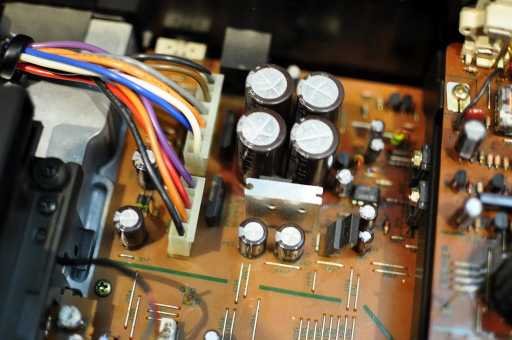
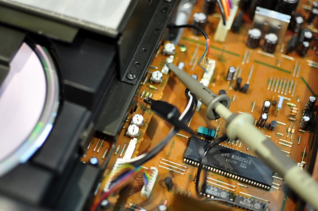
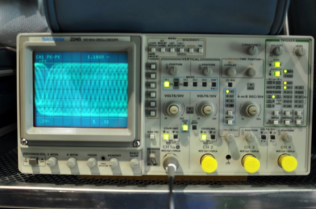
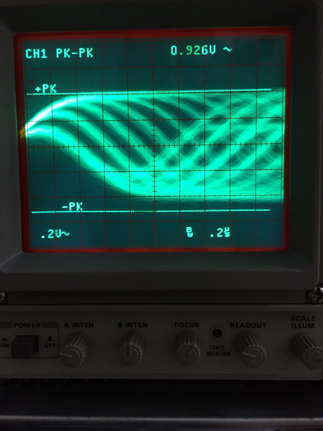
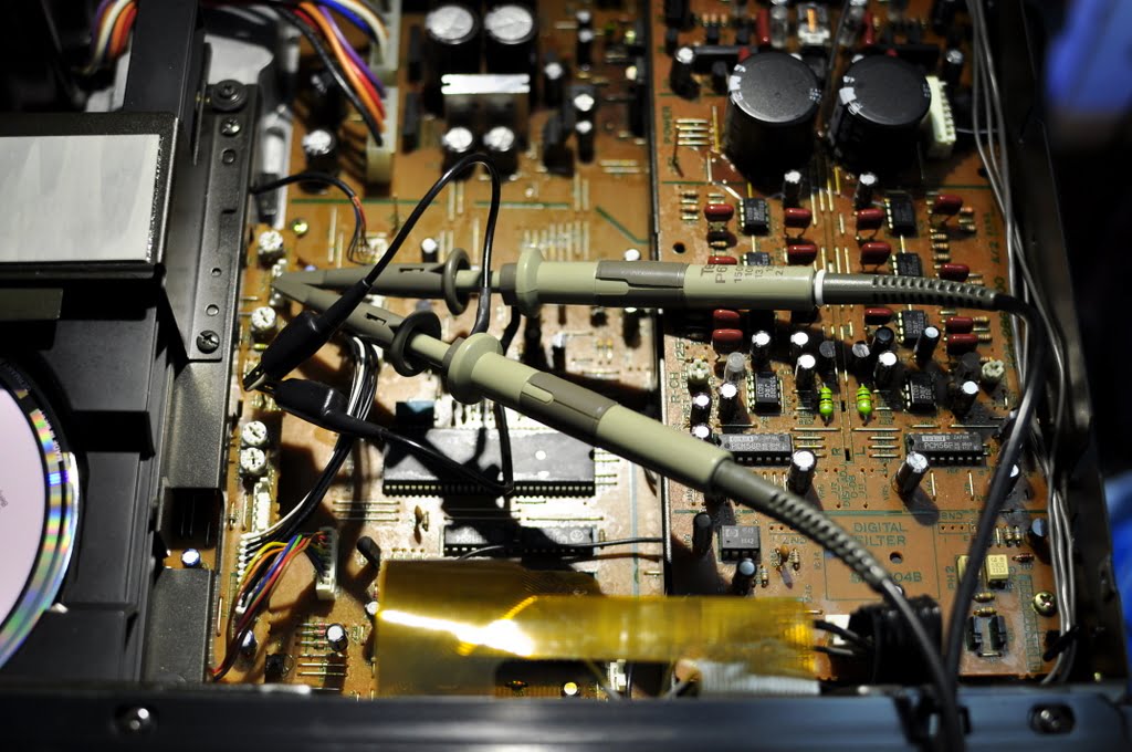
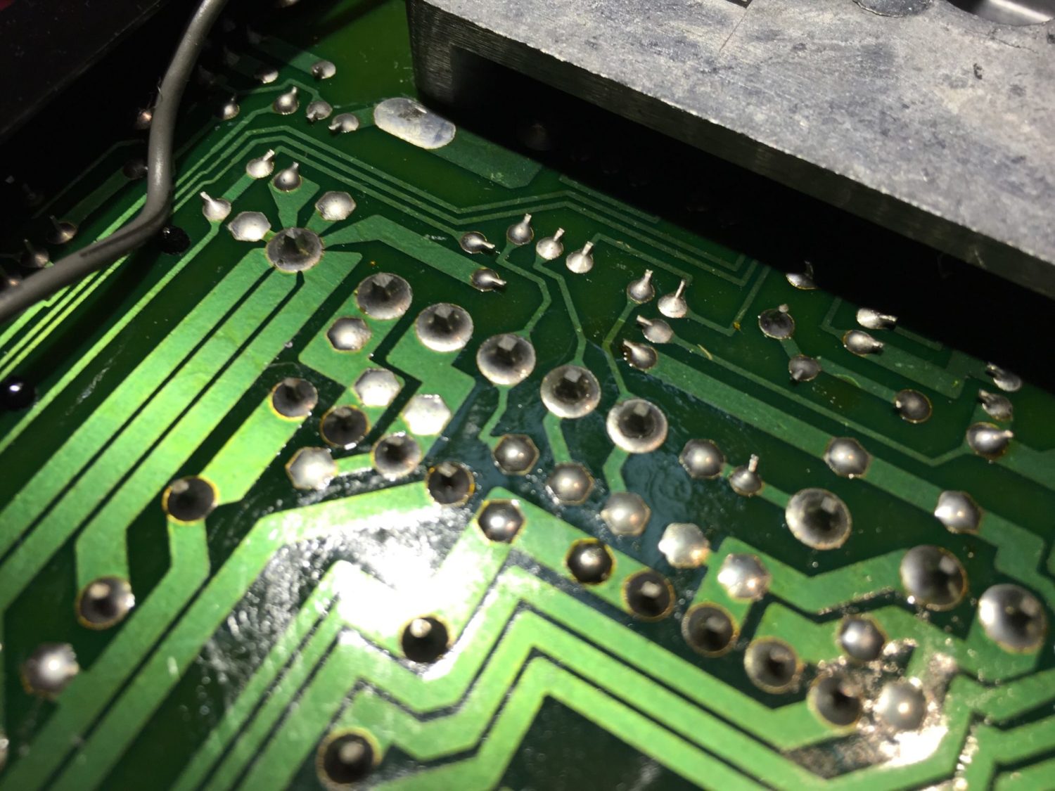
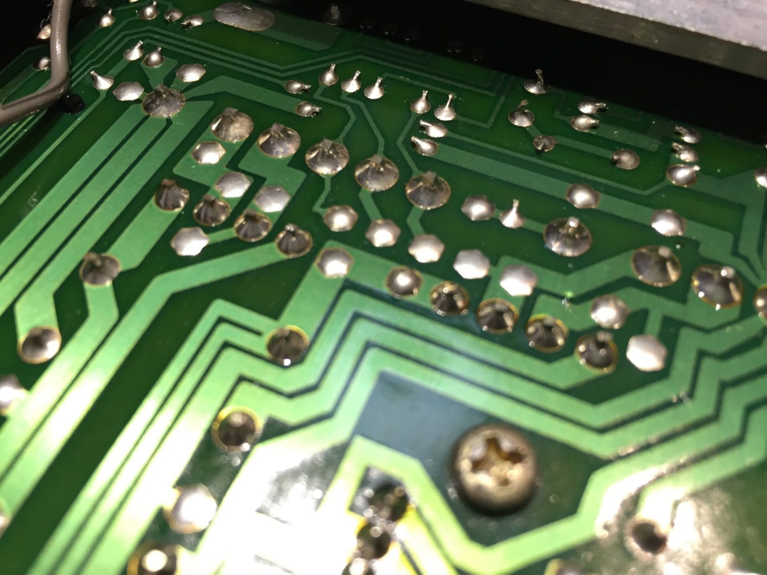
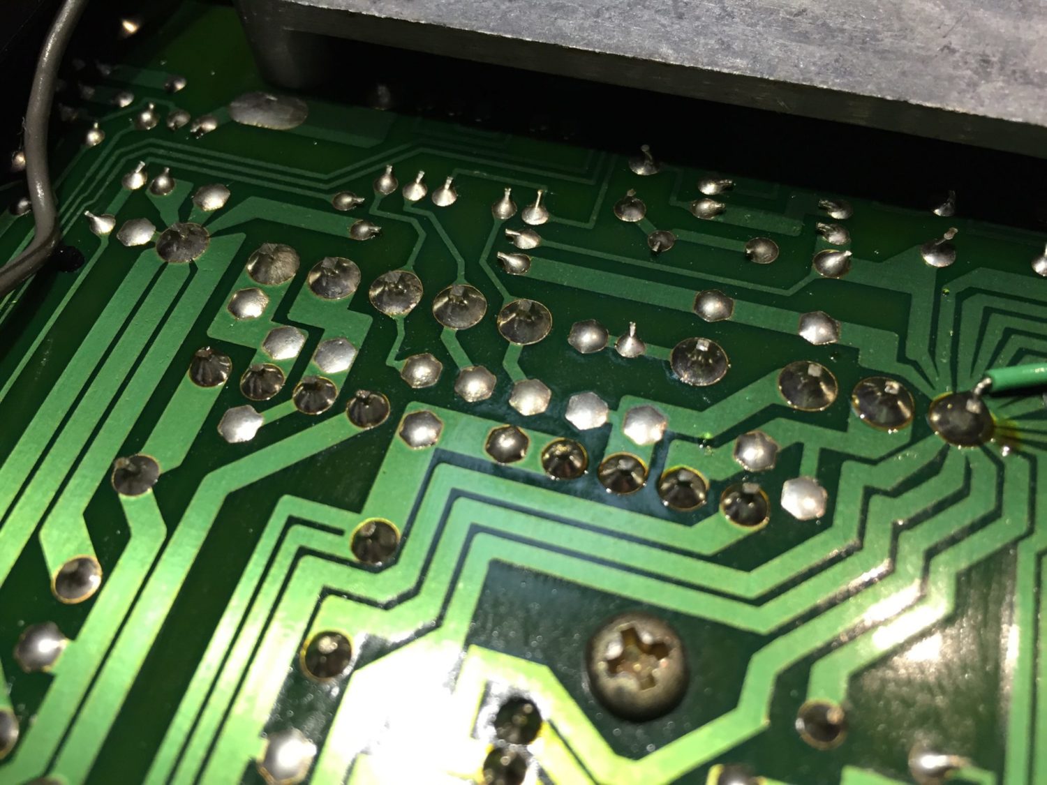
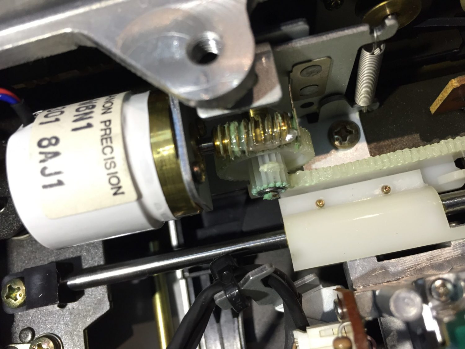
Both of my customer’s Kenwood D-3300P CD players required careful service. One was not reading discs properly, the other made an awful clunking sound when loading a disc and had some power supply issues. Both players benefitted from an optical clean, tweaking of laser focus and tracking servos and gain, one had a spring that a previous tech had failed to re-attach and some dry joints in the power supply that I reworked.
After a bit of Liquid Audio TLC, both players work superbly once again. My customer tells me they both sound better too. They should, as the cleaning and adjustments I made will certainly have improved the accuracy of reading data from the disc and therefore reduce the error correction needed. The power supply re-working I did will improve every aspect of player operation.
Discover more from LiQUiD AUDiO
Subscribe to get the latest posts sent to your email.



Thanks, you did a wonderful job. I own 2 DP-1100D with the same die cast part. I do have DP-1100SG and 990SG with an even better laser mechanism and also a very nice die cast part. kenwood at its best. Look to the space frame of a KD990, I love it. Never had problems with my Kenwood stuff. I am still looking for a DP-3300D (Europe). Kind regards, Wilfred
Thanks Wilfred for your comments. Yes lovely players and you are very lucky to have several of them!!
Io ne possiedo 1 in ottime condizioni
English: I have 1 in excellent condition
Wonderful job, I learned so much how to service this player! Do you have a tip what to look for if analog outputs are not working? Since I’m in Norway it’s not an option to use you guys for repair
Hi Gunder, glad you enjoyed the article! As a general concept, you should first ensure all power supply rails are present and accounted for. Then I’d want to work backwards from the outputs, to find out where the signal disappears. Our advisory service is available for a deeper dive of course, should you need it. You can access it via the contact page or store.
Thank you so much for taking time to answer, I will start from there – I wasn’t aware of the advisory service, will look into it when I get stumped. I really enjoy this entire site, so much nice work and components to enjoy – have a nice day!
Thank you for taking time to answer, I will try this and maybe seek advice when I get stomped 🙂 I thouroughly enjoy this site, so much nice work and equipment!
No problem, best of luck resolving the problem!
Hello Mike,
I’m having a power problem with this CD player. It won’t turn on. I looked for the “base” fuse, but I can’t find it!
If you have any information on this, I’d love to hear it. Thank you in advance for your attention.
Hi Yoann, thanks for your question! I don’t have one of these here to look at, and I cannot recall where the fuse is located, unfortunately. There aren’t many places where it can hide, though; hopefully you’ve managed to find it. Naturally, you need to determine if/why it failed.