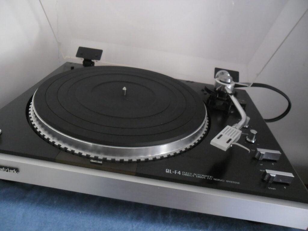
I recently worked on a very cool and lovely old JVC QL-F4 direct-drive, fully automatic turntable. Let’s take a look inside.
The JVC QL-F4 is a mid-range deck from the once-great JVC. Even in the late ’70s and early ’80s, JVC was not known for its hi-fi separates. This is a shame because this series of JVC turntables had great specs. This deck is quite unusual in terms of the platter, styling and cool LED strobe illuminator. It also allows for repeat playing of records, great for parties!
UPDATED, 2023. Wow, this takes me back! Decks like this were still being thrown in the bin when they failed, rather than being repaired, when I wrote this. Most hadn’t heard of the JVC QL-F4 when I repaired and wrote about this one, so I’m pleased if the article has inspired folks to get into turntables or try their hand at repairing them. Thanks for visiting and for being part of the journey over the last decade 🙏
Issues
I’ve worked on many of these lovely old turntables over the years, so feel free to read a bit more if so inclined. You can also find more information here.
This JVC QL-F4 came with a couple of issues. The bottom case was badly cracked and had been dropped at some point. Also, the platter would often not spin up on its own, requiring a little nudge to get going! Naturally, the owner wanted these problems repaired and for the deck to be serviced and brought back into the correct working order and factory spec. He also wanted me to replace the headshell and cartridge.
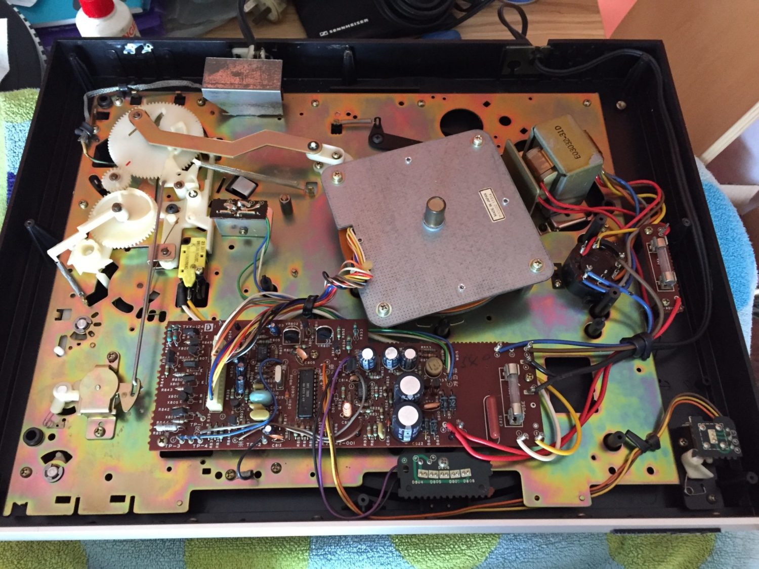
To begin, I cleaned the deck. This helps me detect any other issues that might be obscured or even created by dirt, something I’ve seen often. I then removed the plastic base and repaired it with a cyanoacrylate glue specially designed for plastics.
Repair
The next job was to inspect the electronics. I figured that there might have been a power supply issue and it’s best to start with the cardinal rule of electronics repair: “Thou shalt check voltages.” The main 22V rail was down slightly, so I adjusted this and retested the deck. She still wasn’t quite behaving herself.
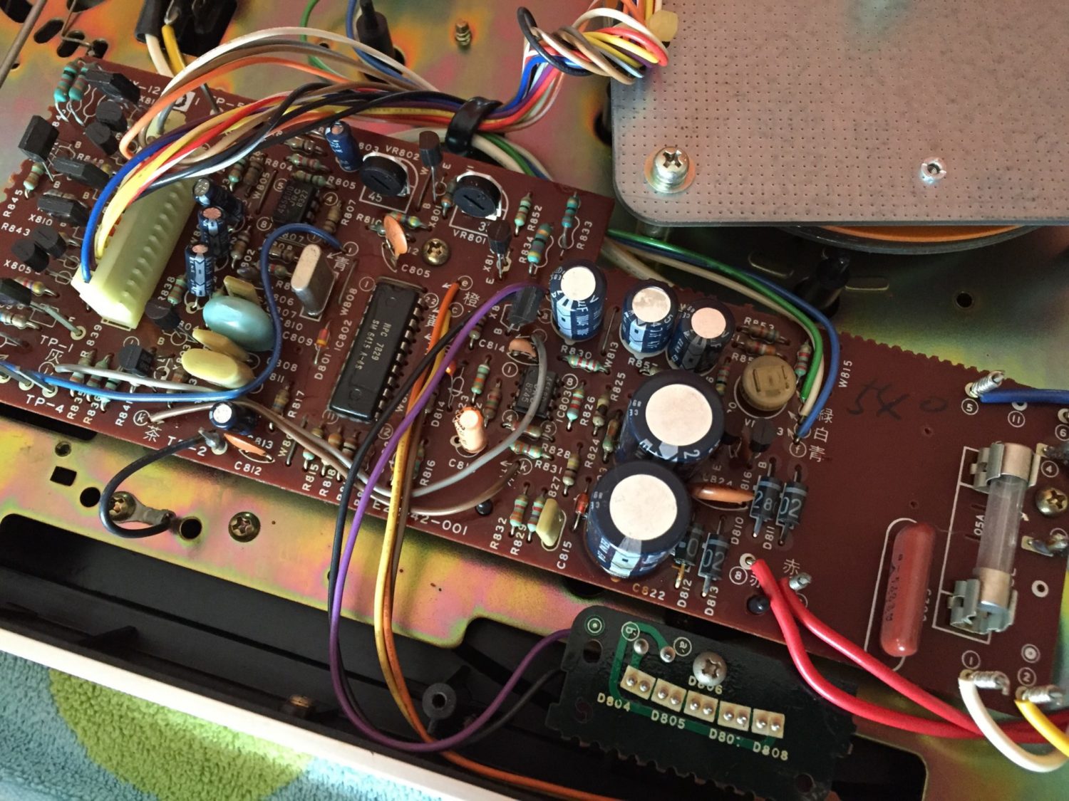
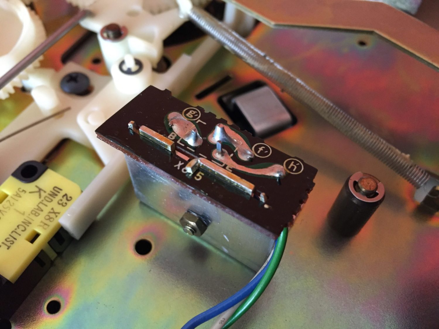
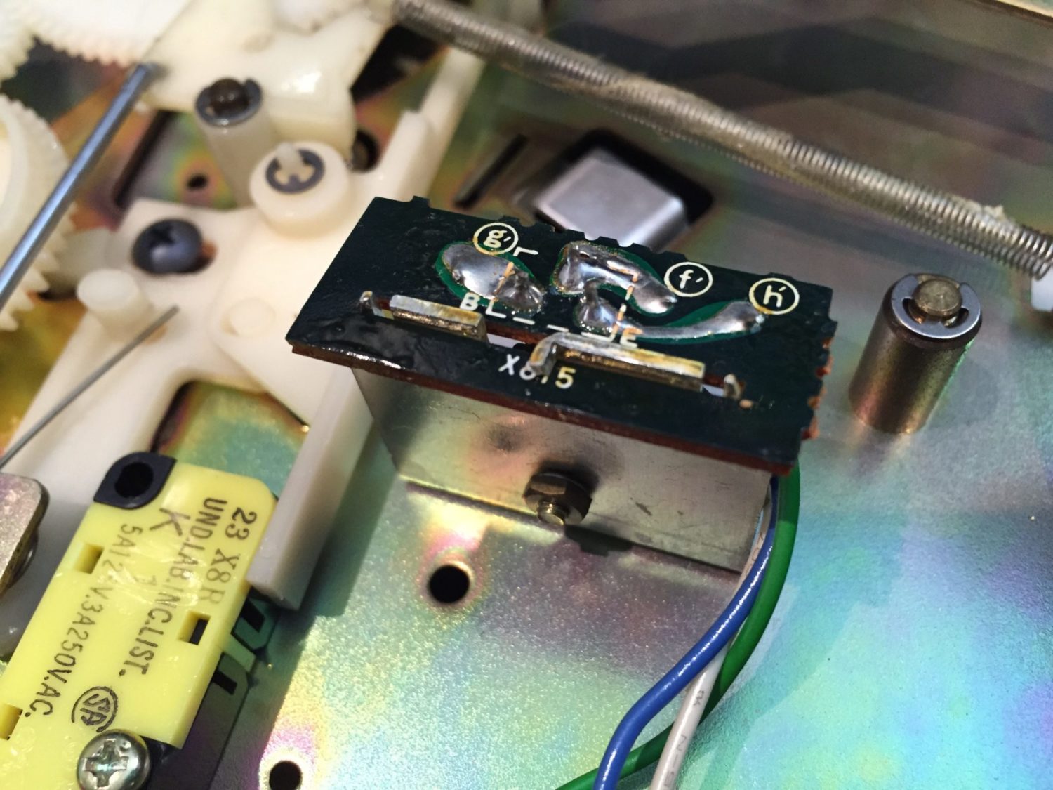
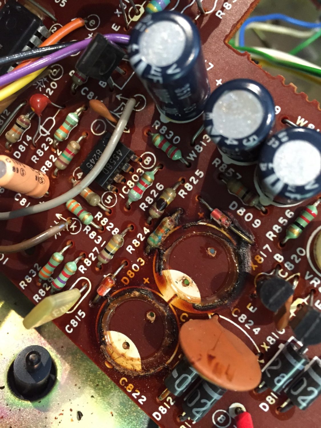
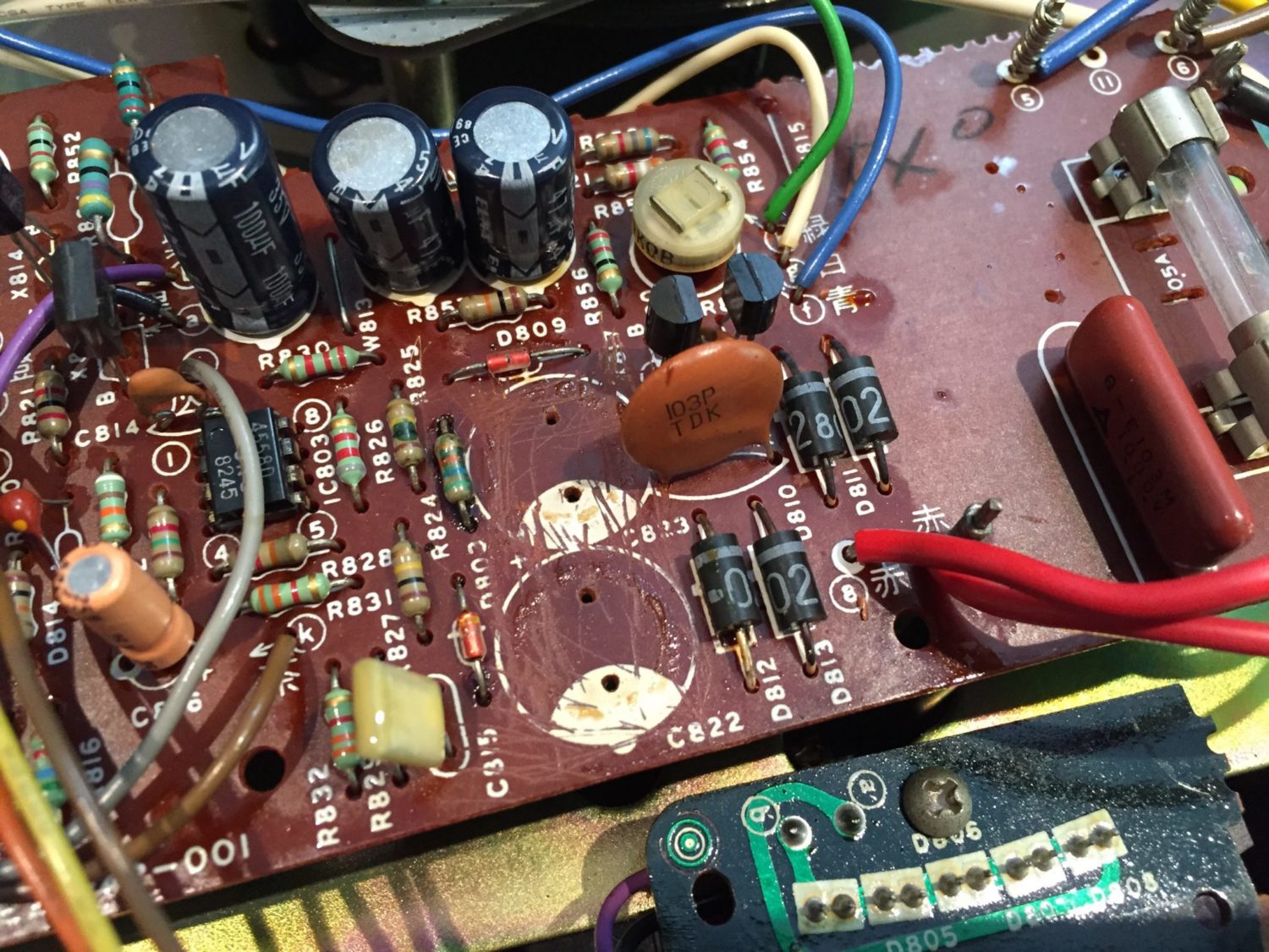
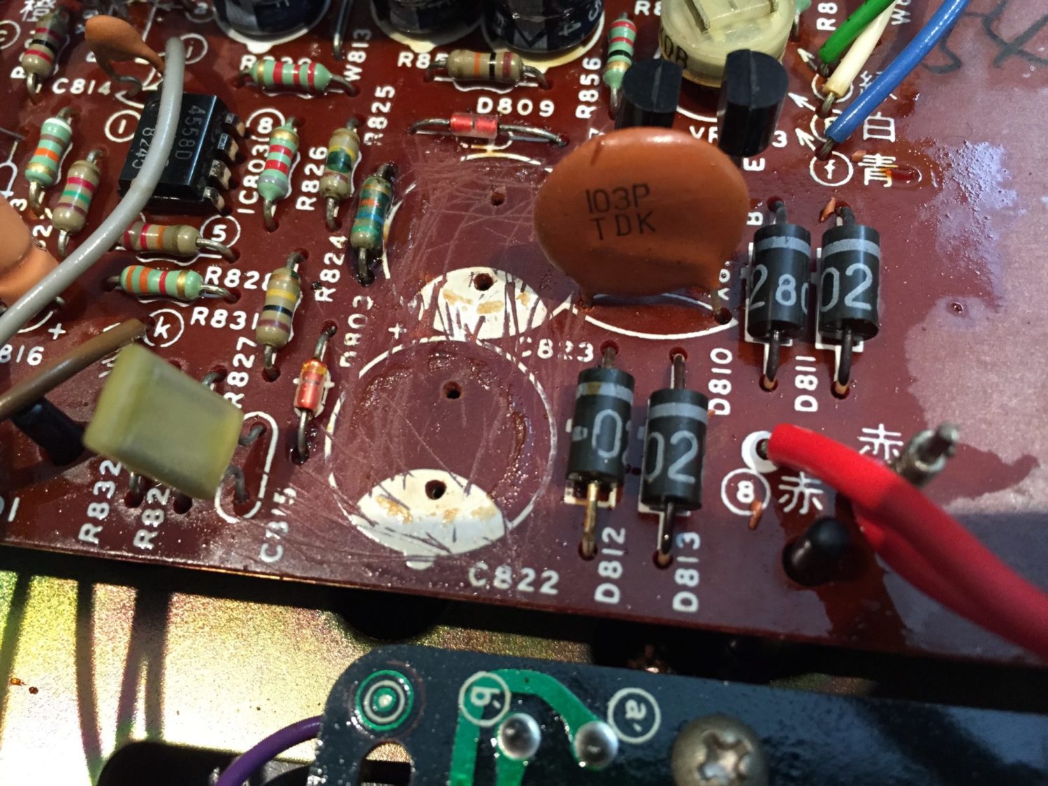
What I did find though was a voltage regulator or series-pass transistor (my apologies, I can’t recall now which it was) that had at least one dry joint and needed re-working. The images below show this before and after some time with the Hakko soldering station.
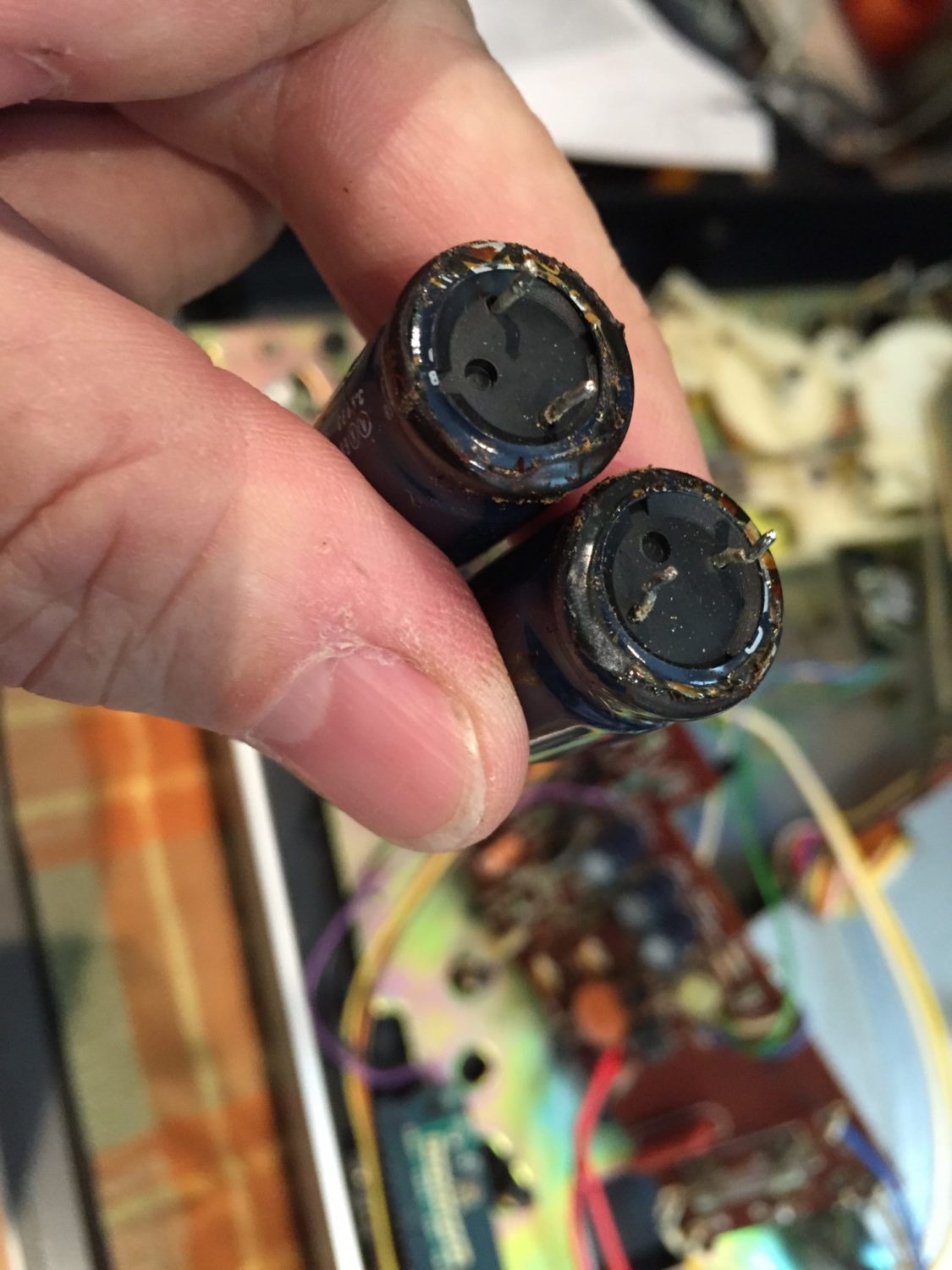
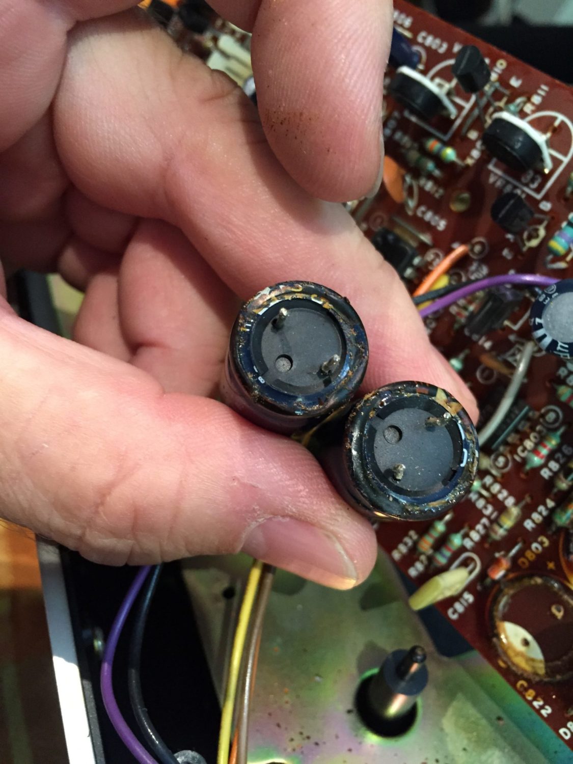
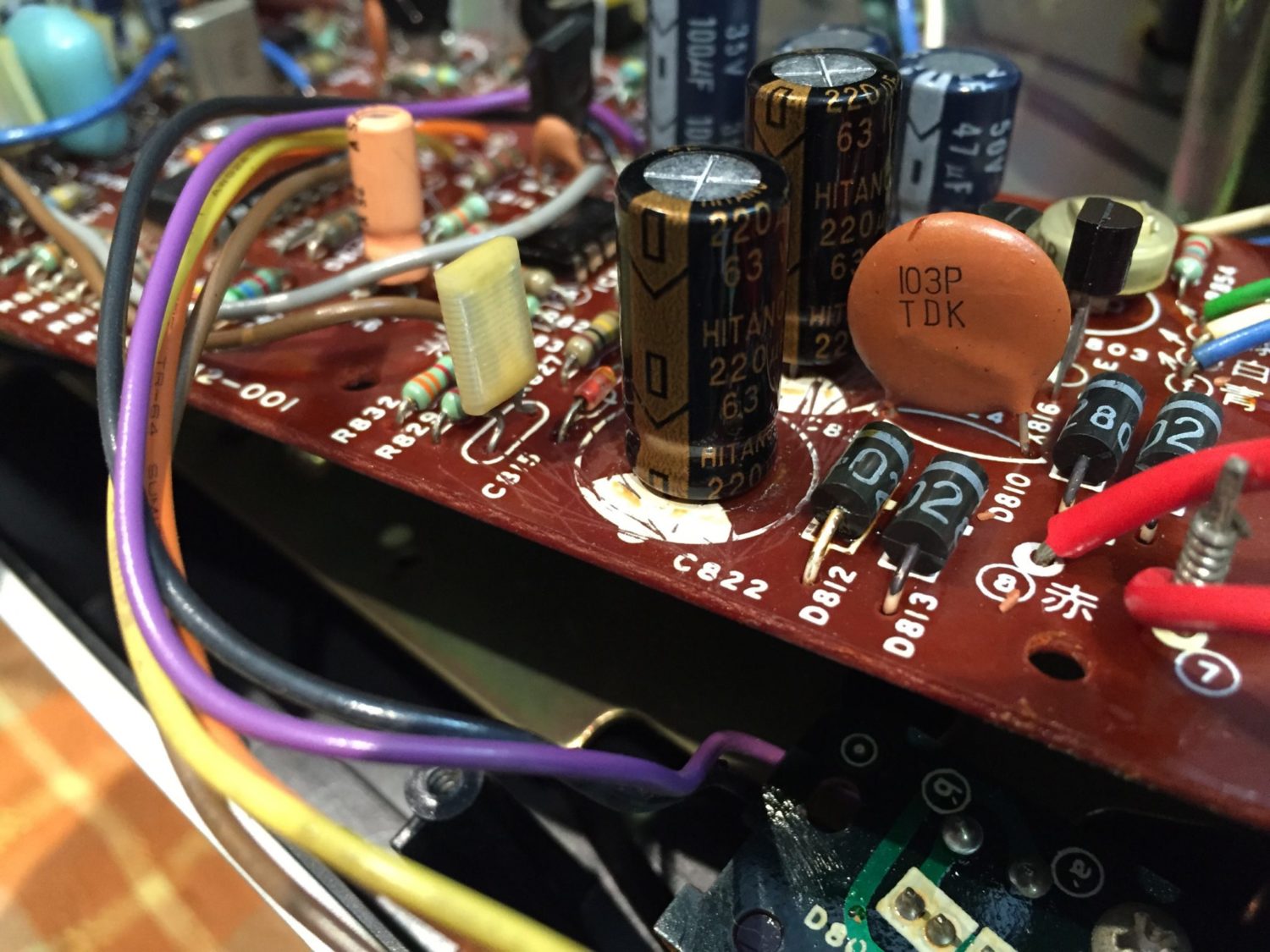
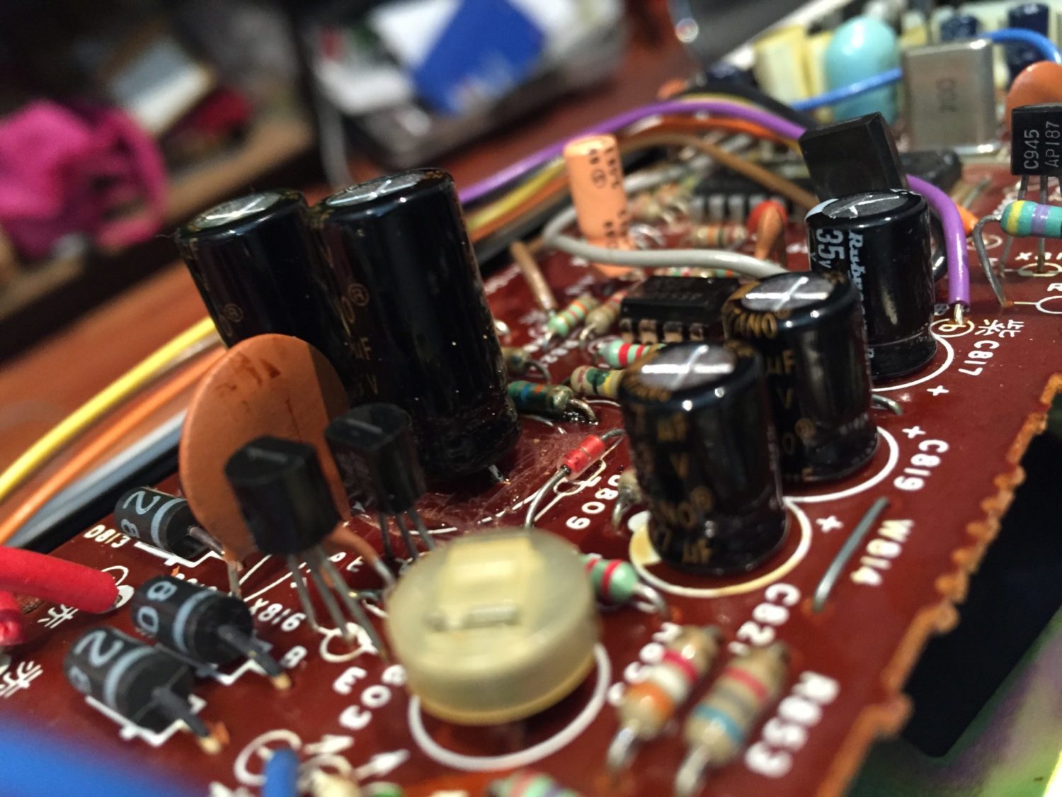
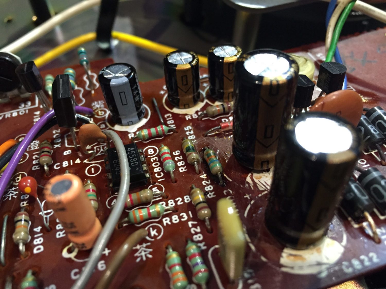
Next, I had a very close look at the capacitors in the power supply area. There was lots of the dreaded corrosive glue around the larger capacitors. This and the affected parts had to go. I pulled the caps, carefully removed the corrosive glue and installed some nice high-temp, low-ESR replacement capacitors.
Retesting the deck showed that I had resolved the issue with poor starting torque as she now spun up every time, without assistance. I readjusted the 22V rail again and that job was complete. Note that I’ve repaired many QL-F4s and issues have included glue damage seen here, completely dead power supplies, issues with op-amps and more. Checking voltages with reference to the service manual is critically important where faults are not immediately obvious.
Mechanical Service
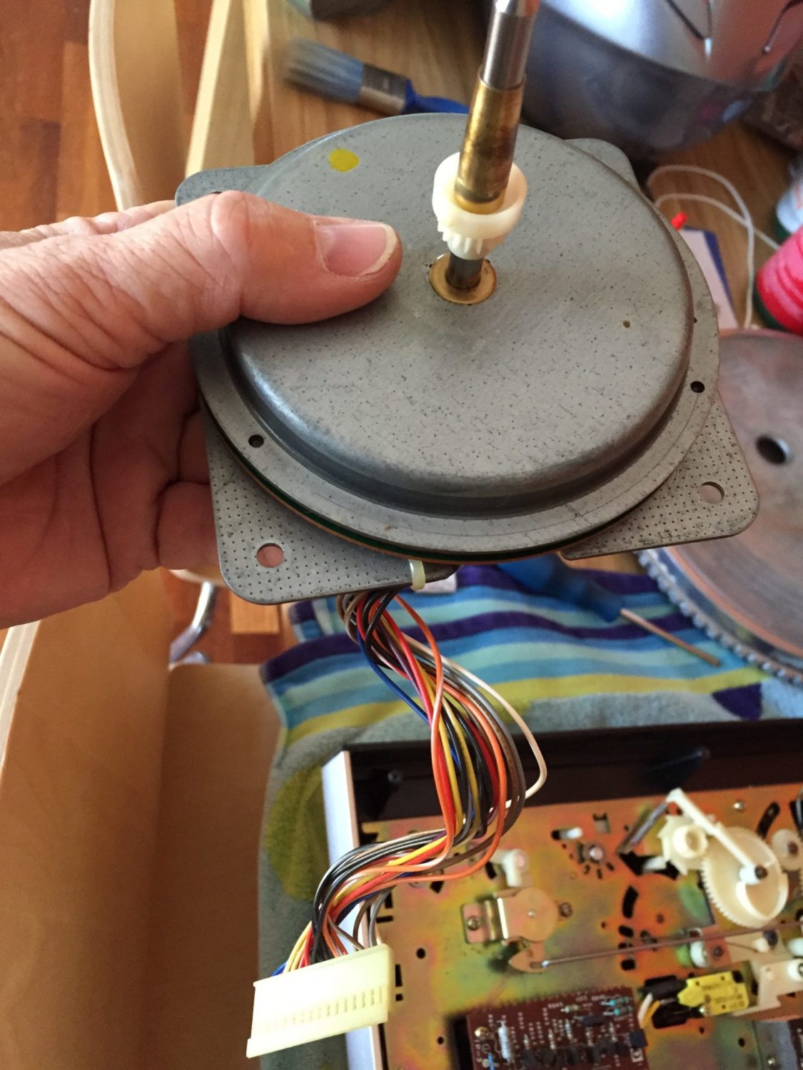
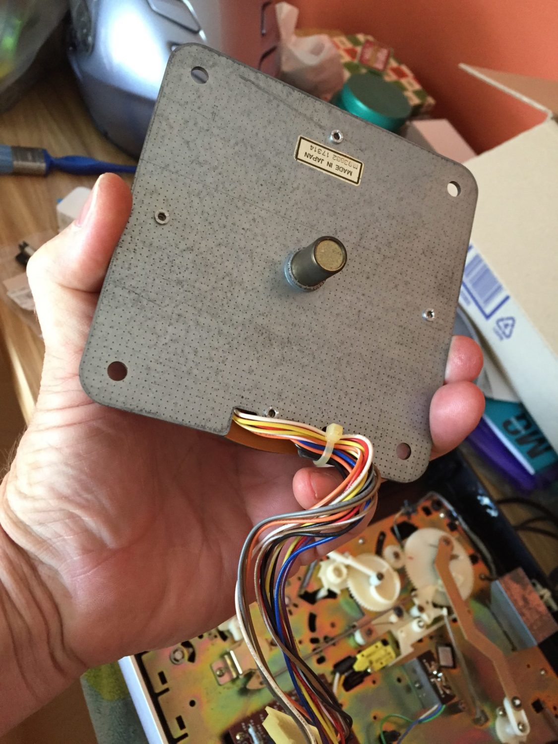
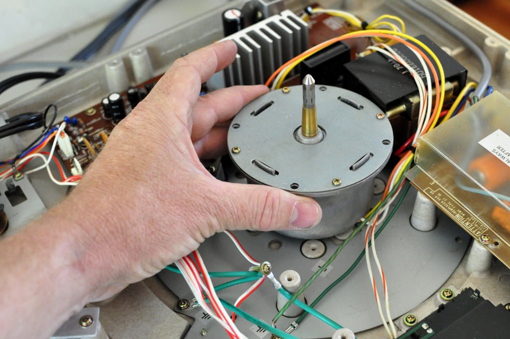
Interestingly the JVC QL-F4 motor appeared sealed and not designed for service. The rotor turned smoothly and with no perceptible bearing free play, so at the time of writing back in 2015, I was not too concerned about this. I learned in later years and after having worked on many more QL-F4s that the motors pull apart. The rotor pulls away from the stator when enough force is applied to it. Thank you to commenters for reminding me of the need to update this article!
So the last couple of steps in this full service involved lubricating various points on the arm-control mechanism, setting up those to allow adjustment of the Quartz lock circuit and carefully checking and re-checking these adjustments to ensure they are perfect and stable over a decent operating period. The service manual outlines the procedure clearly.
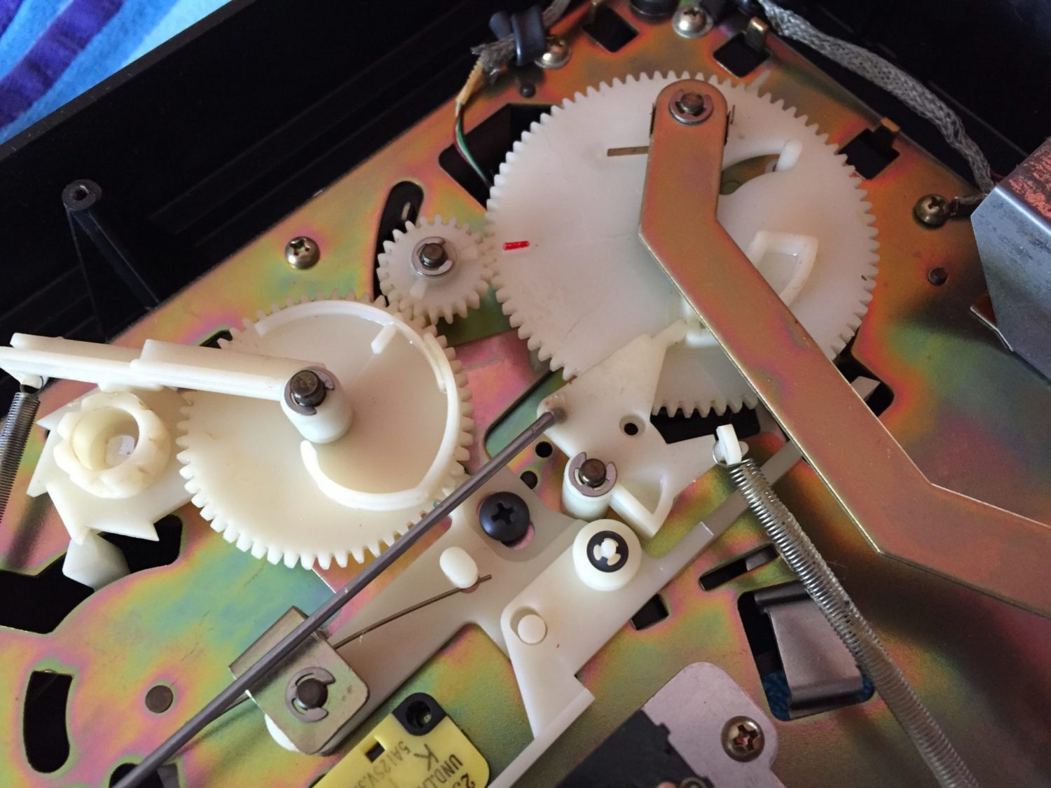
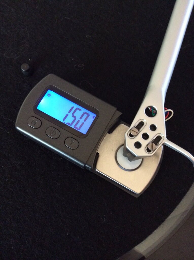
After that the newly repaired bottom went back on, I installed the supplied Stanton cartridge in the supplied JVC headshell, installed that into the tonearm and then carefully aligned the cartridge and set tracking force.
Results
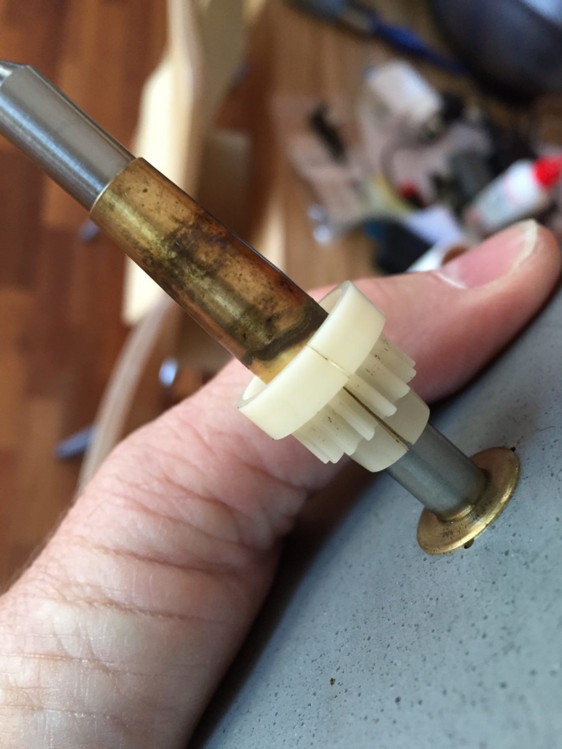
The deck now plays a record very well. It is quiet, wow and flutter is very low and all automatic functions work well. Note that the drive gear attached to the spindle is cracked and it is only a matter of time before the arm return function fails. Even this is no big deal though, the deck itself will continue to play records for many years to come!
As always, thanks for reading and don’t hesitate to let me know if I can assist with your JVC turntable, or any other for that matter!
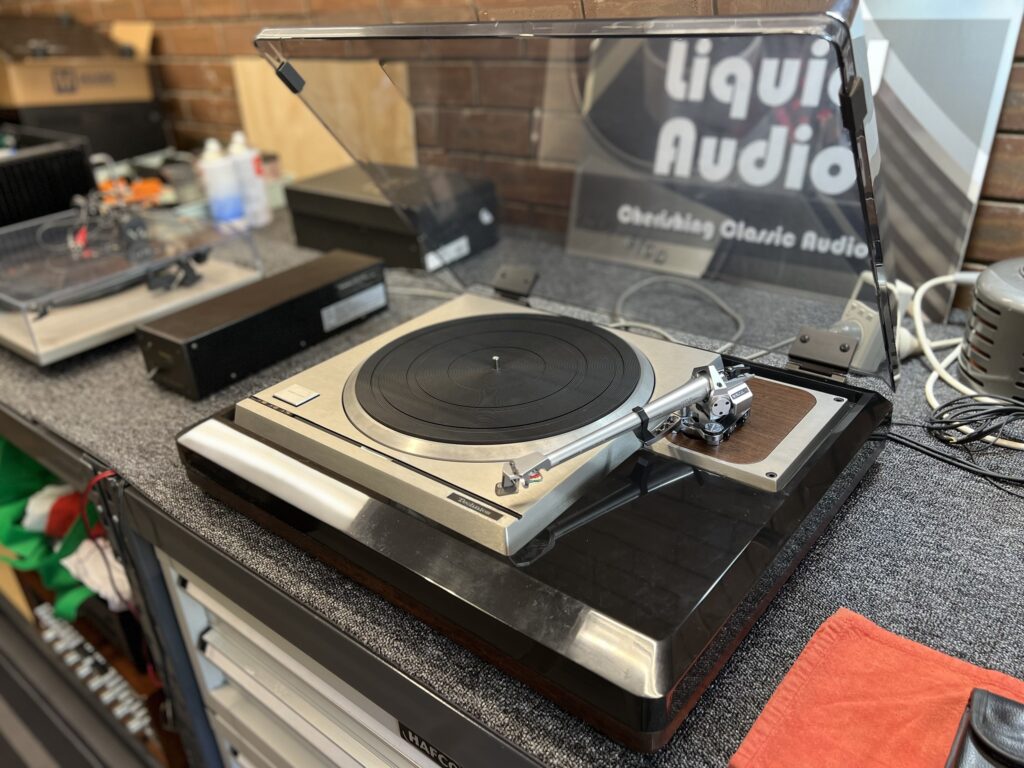
Discover more from LiQUiD AUDiO
Subscribe to get the latest posts sent to your email.



Beautiful article. Just had my QL-F4 apart to fix its inability to maintain speed. This one has not been dropped. I cleaned the 33/45 speed switch with alcohol and air-gunned it dry. I rotated and returned to original the two pots that seem associated with speed. I saw the corrosive material under the caps that you have detailed and it is eating resistor legs. Did nothing for that. Now it maintains speed without wow and flutter but the QL leds are flashing like crazy monkeys. Fun. Thanks for your article.
Great job there JJ, really pleased the article helped and that you fixed your deck! Mike.
HI Mike, My ql-f4 turn table quartz lock still wanders around after lubercating is there quick fix,it throws the music sic.regards dave.
Hi Dave, no quick fix unfortunately, but an experienced eye needed and some TLC I think. Are you able to get your deck in for service?
awesome shot by shot article!!. By the way do you recieve many of these Turntables for sale
Thank you very much, most decks are repairs for people, but occasionally a deck comes up for sale. Regards, Mike.
Can you identify the resistor at d803 it’s above the left Leaking capacitor? Thanks
Great post and photos that proved very helpful for me.
I recently found an old JVC QL-F4 turntable in a pile of junk turntables in someone’s garage. My neighbor offered it to me for $25 with a couple vintage LPs to boot, so the deal was done. Aside from the dirt and crud of many years of neglect it didn’t look bad except for the usual scratches in the dust cover. I polished out the haze and scratches with some automotive plastic polish. The electronics and mechanical operation were both good. Just to head of future problems, I replaced all the power supply electrolytic capacitors with upgraded low ESR types that had higher voltage and max temp ratings. In the process of replacing the capacitors and cleaning the corrosive glue off the circuit board, I managed to break the D 809 5.6 volt zener diode that I also replaced. The owner’s manual came with the turntable and was very helpful. I managed to re-calibrate the quartz-lock without the usual oscilloscope. A new elliptical stylus was installed in the Stanton 500 cartridge for $14. The total cash out of pocket was less than $20 for the repair parts. With a little cleaning, lube, and the modest sum of $45 I have a great sounding turntable. This vintage TT has better specs than many new production models. I may be adding an additional headshell and the Audio Technica MLA 440 cartridge, or possibly the Ortofon M2 Blue in the near future.
Hi James, thanks for sharing this story and the great result you achieved with this deck! Cheers, Mike.
Hey Mike I just bought this deck, it was one owner, original box, etc, very nice shape. I have the cracked gear too, I was thinking maybe I can glue it. The crack or split is just starting on the gear. I don’t know anything about electronics…forgive me….are the capacitors soldered in or are they plug in. You just made it sound so simple. Thanks Darcy
Hi Darcy, so the drive gear is easy to repair, just clean with a fast drying solvent that won’t harm nylon and glue with cyanoacrylate (super-glue) adhesive. Try to clamp the gear gently though, to ensure the drive ratio doesn’t change from it not being snug on the shaft. Capacitors and other electronic parts are soldered in and need to be carefully desoldered with a desoldering tool or braid and good technique. They can then be replaced with a quality part that should last many years.
Greetings Mike. Thanks for posting this. I have the same model that is my main livingroom unit. The start / auto switch slips on its shaft and I am planning to tear into there and repair it. After a quick survey of the situation, it looks like I have to completely disassemble this thing to get to that switch. Any pointers on that? Any shortcuts? Thanks for your feedback. It’s a great TT.
Greetings Michael! Thanks for your question – to be honest, without the deck in front of me, it’s hard to offer tips that might be helpful. My main tips are always to make sure you have good tools and the skills to undertake such work. If those bases are covered, you will find the work fairly straightforward I think. Take your time, use the opportunity to assess any other work that might be required, lubricate the motor and so on. Let me know how you go or if you get stuck!
Hello. Great article with meaningful pics and explanation! I have this turntable. cleaned the speed selector switch as per you instruction and no more flutter at 35! I too have noticed the large caps that have that weird dark substance that appears to have “leaked out” is that what is called a “leaky cap”? what symptom should i expect if that condition is left? So far the table has been working great for years. not sure what caused that to happen. Thanks again!
Hi, nice article! I restored my JVC QL7 a few years ago by replacing the caps. I was wondering if you could direct me to a list of the caps in this QL–F4. It looks like there may not be as many to replace, but a list would really help.
Thanks!
Rick
Hi Rick, thanks for that. I don’t have a list available but suggest you make one by opening her up and having a look, or alternatively by locating a service manual. The manual should have a list of parts, including caps. Cheers, Mike
Service manual can be found here: https://www.vinylengine.com/library/jvc/ql-f4.shtml
Great post and great pics. You obviously take pride in your work. I run a Ql F4 with a 2M Red and like it very much. Considering buying another one here locally for sale. Are you still restoring Tables for others? Kinda hard to find someone you can trust to do quality work that cares.
Hi Roger, thanks for getting in touch and for the feedback, much appreciated. Yes I run a full time business servicing, repairing and restoring hifi equipment, so I’d be very happy to assist with your deck. I suggest you give me a call and we can have a chat about your requirements! Regards, Mike
Thank you Mike. If you want to email me your contact info….. bighorn78@live.com. Can I ask where you are located?
Hi Roger, all of my contact info is on the homepage, as well as the Contact Me page. Feel free to give me a call today, anytime from 10 am Perth time.
Hi Mike, Just found your home page and its an awesome site..you do very nice work. I do have a question that I can not find an answer for with that plastic gear. Could you switch the motor out of a QLA2 (same deck but it is semi auto) and replace it in a QLF4? I do have one with a nice gear.
Hi Tom, thanks for your question and glad you are enjoying the site! Yes, in theory, as long as everything fits and they are truly identical. Another option might be to 3-D print a new gear, that would be my preferred way to have two working decks out of the pair.
Hello Mike, I just acquired a QL-F4 and will be following your great cap replacement and clean up guidance. This table warbles with a high degree of W&F, but speed is close (just a little under) in 33 & 45. Also, the strobe is out. I’ve examined for poor solder joints and reflowed those that look weak. It hasn’t helped. A couple of the resistors near the large capacitors are gunked in glue and look dark on the soldering side. However, they test within spec. Any thoughts on the strobe issue? Thanks, Phil
Hi Phil, thanks for your question and glad you enjoyed the article. I’ve repaired power supply issues, motor speed control and feedback issues, bad caps, corrosive glue and more in QL-F4s over the years. Each unit tends to be a little different and sometimes faults interact, adding to the pain. Wow and flutter could indicate a mechanical or electronic issue, further testing will reveal the cause. The dead strobe could be down to a broken power supply or tube. If you are able to, I suggest measuring voltages, starting with the power supply and working forward. If you have access to a good technician familiar with this sort of equipment, that’s the best option for most people.
Great article on a great turntable. I would like to note that the motor is not sealed. The motor consists of a spindle with 2 magnets along with a control board with a bushing that has a Teflon or similar disk in the bottom that supports the rotation of the spindle and sets the gap between the rotating magnets. and the control board. Otherwise, the magnet would drag on the board and its traces. One can separate the spindle and the board by pulling whit enough force to overcome the pull of the magnet against the bottom of the bushing. Once you have sufficient distant between the board and the magnet the whole thing will slide apart. I know this from research I did in order to address several issues I had with my 47-year-old QL-F4.
See the YouTube video @ https://www.youtube.com/watch?v=PbAWLPZGnFI approx. 13:25 into the video.
Hi Frank, thank you and glad you enjoyed the article. You are absolutely right, the motor does come apart. I discovered this many years ago, but it was after writing this article back in 2015 and I unfortunately forgot to update it. I’ve now updated this and made a couple of other changes to the article, thanks again for visiting!