In this second article on the Marantz SC-80 and SM-80, we look at the SM-80 power amplifier and a tricky repair and restoration.
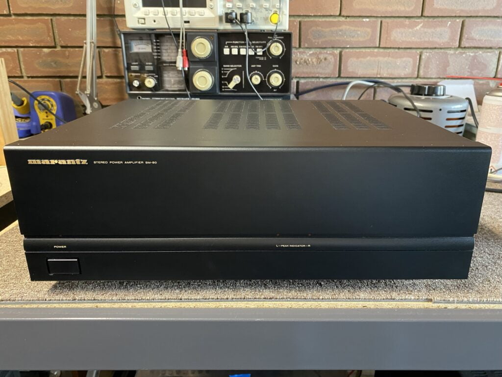
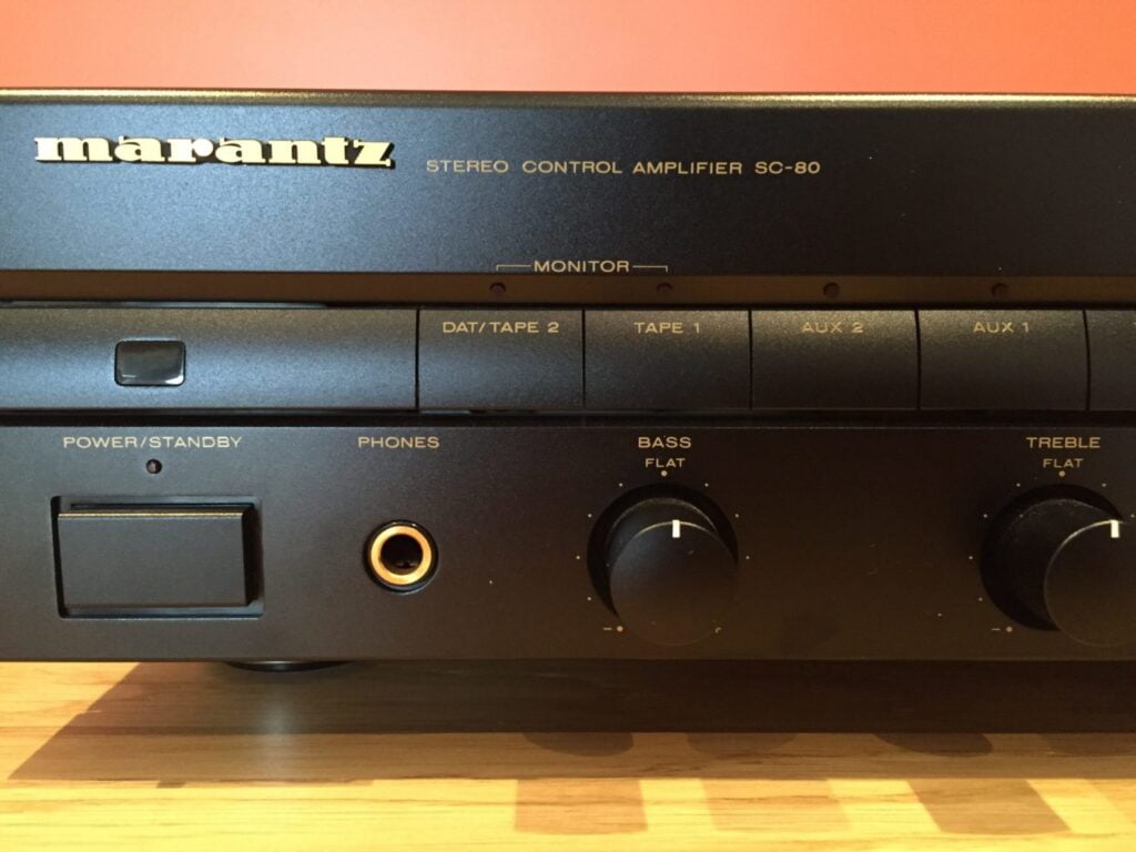
The Marantz SM-80 stereo power amplifier is a reasonably powerful, well-made, mid-range consumer amplifier from around 1990. It typically sold with its companion, the Marantz SC-80 preamplifier and I have just finished repairing one of those so be sure to check out that article too.
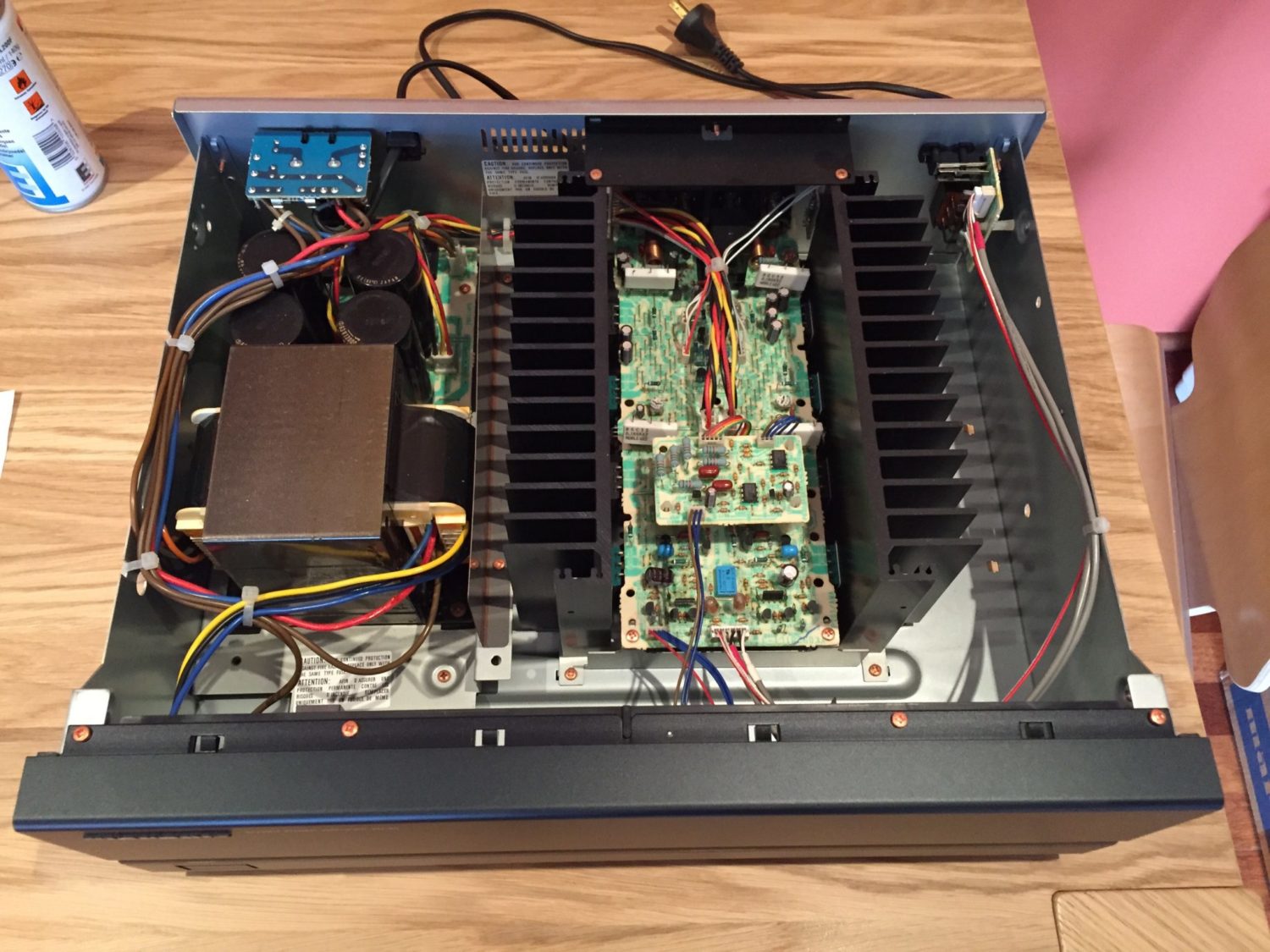
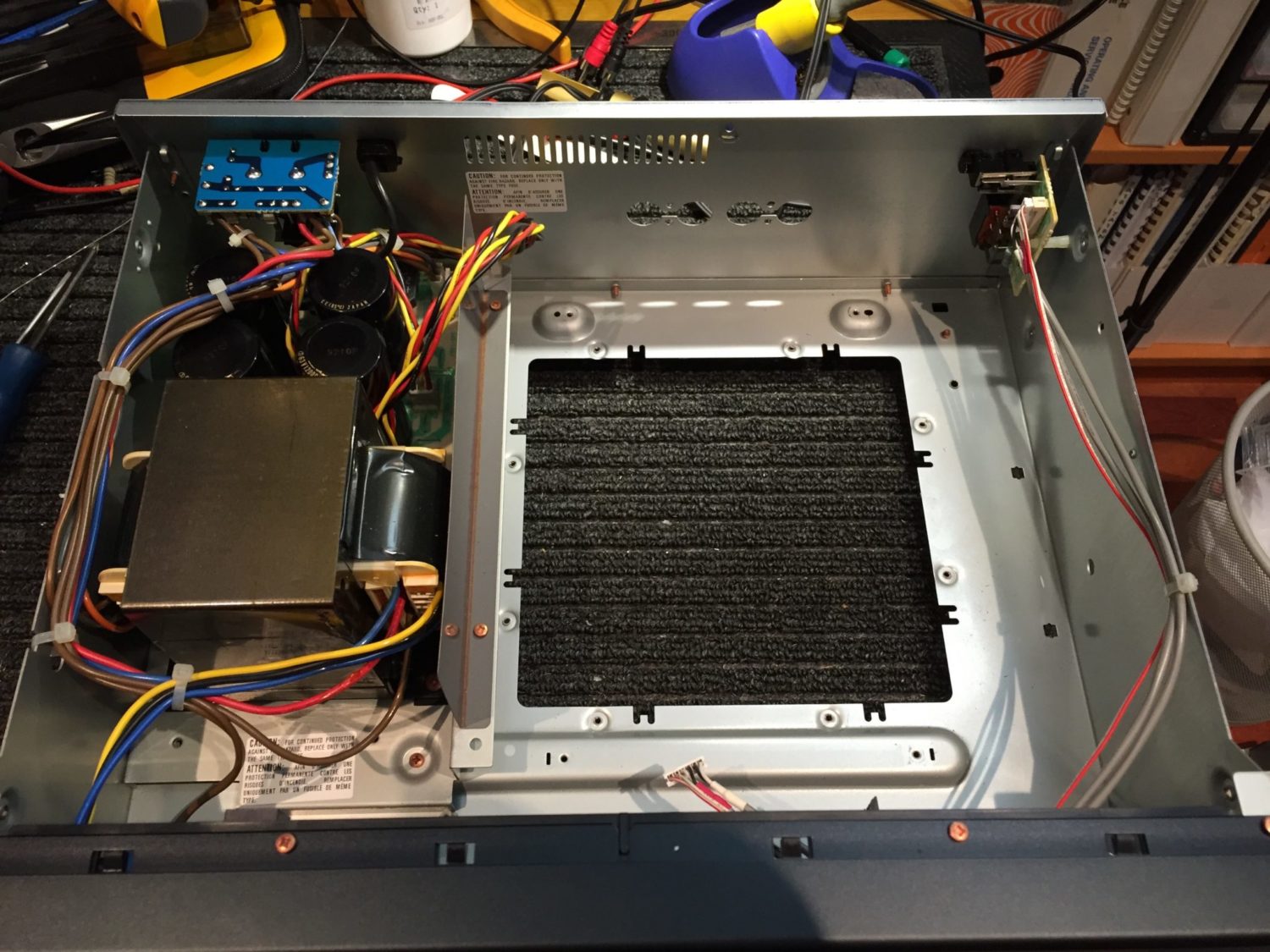
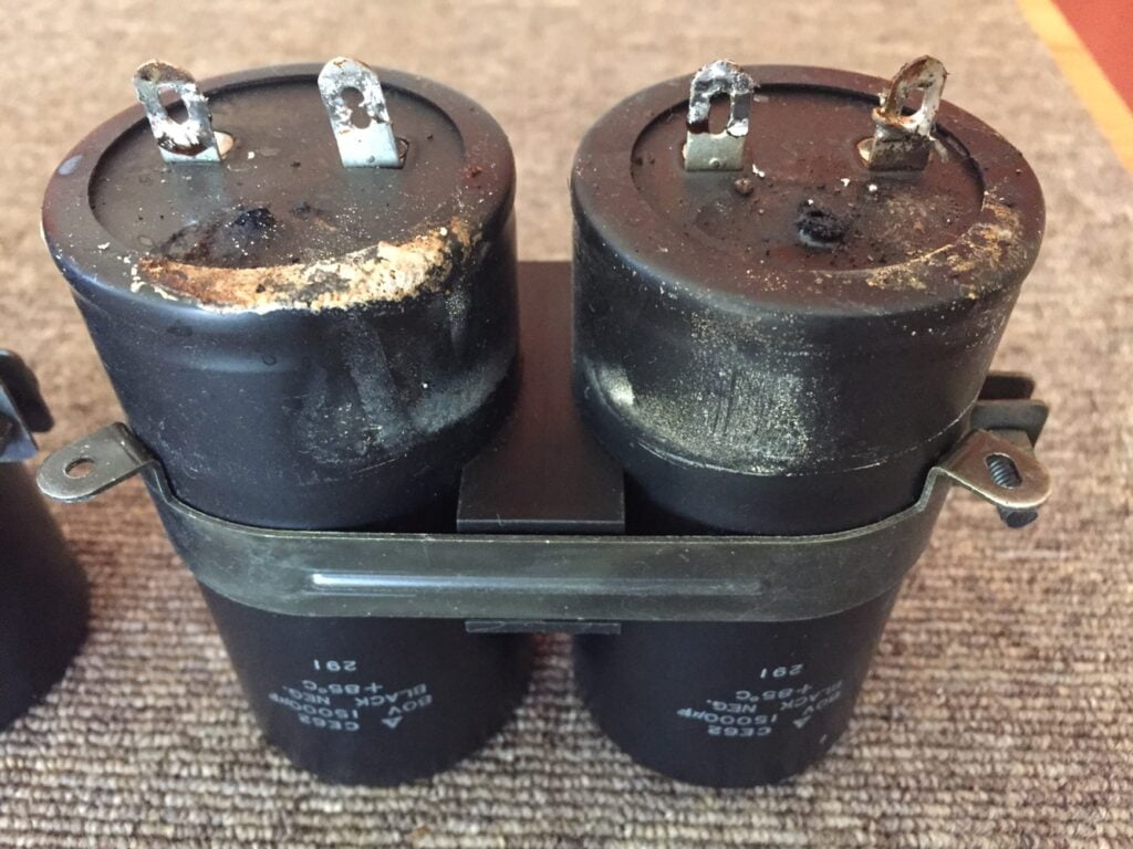
The SM-80 is a typical class A/B design and runs a fairly low bias current. It uses a FET input for high input impedance and is an easy load for any preamplifier to drive. The power supply is reasonably beefy, with 4 x 12,000uF capacitors feeding +/-53V rails.
The SM-80 was designed with serviceability in mind, unlike a lot of modern gear. The SM-80 was delivered to me with a fault where the protection relay would not allow correct operation until some 15 or 20 minutes after turn-on. This had progressively gotten worse over time and indicated that an overhaul was likely required. My initial thoughts were a leaky cap or an open or high ESR cap in the circuit associated with the protection chip.
Specifications
If you want some more information about the Marantz SM-80 or the SC-80, pay a visit to The Vintage Knob for more details. The HiFi Engine kindly provided these specifications:
Power output: 100 watts per channel into 8Ω (stereo), 300W into 8Ω (mono)
Frequency response: 20Hz to 20kHz
Total harmonic distortion: 0.02%
Damping factor: 200
Input sensitivity: 1V
Signal-to-noise ratio: 121dB
Dimensions: 420 x 132 x 334mm
Weight: 13kg
Year: 1990
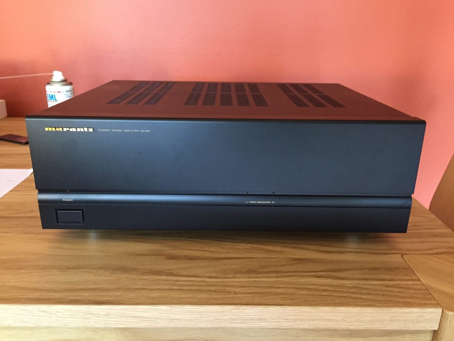
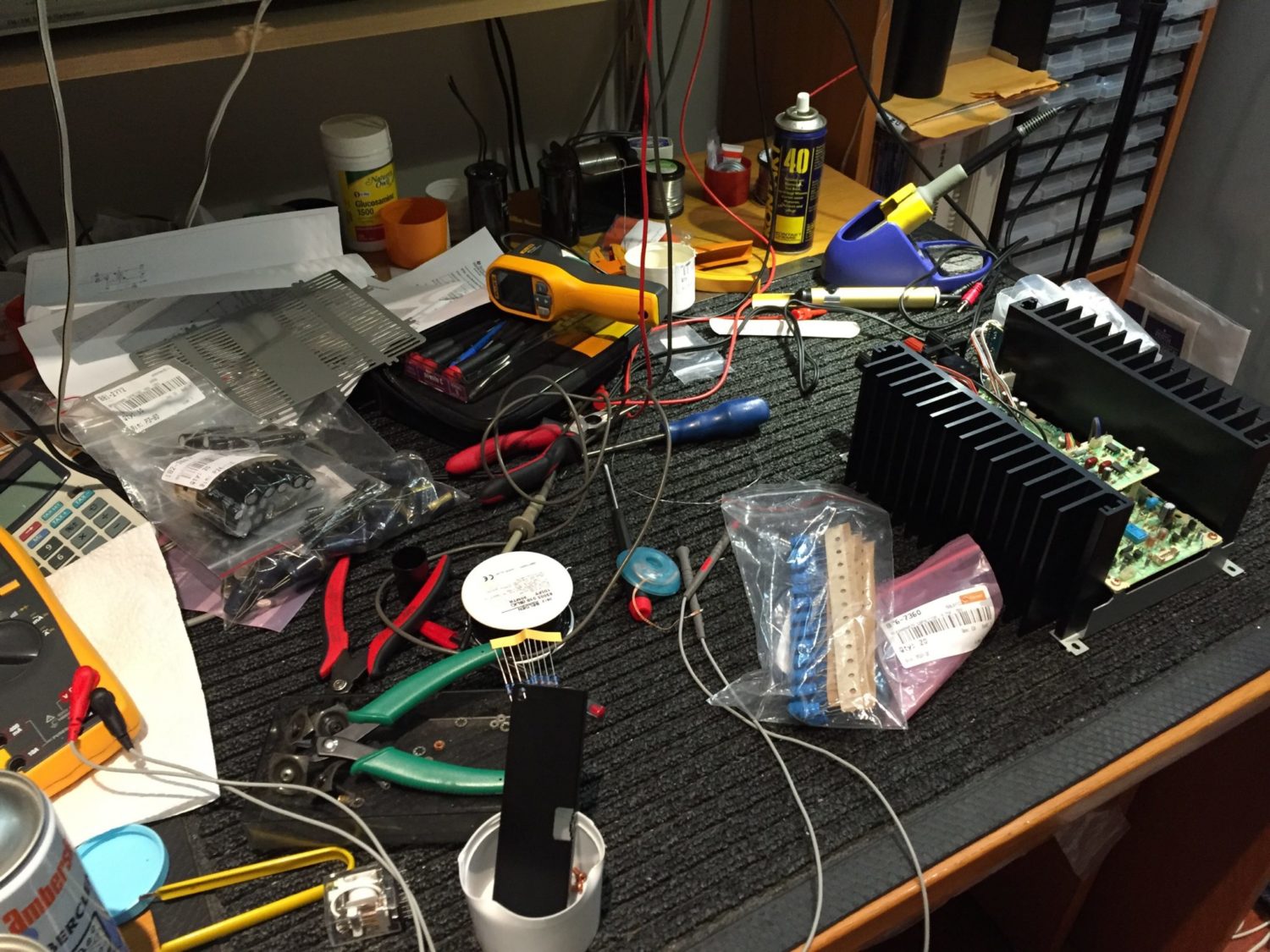
Initial testing of the SM-80 confirmed the owner’s description of the symptoms and I immediately opened up the amplifier and looked around for anything obvious. Nothing except a few dry joints jumped out at me, so I reworked those and retested the amplifier – same symptoms. This indicated to me that this particular amplifier would most likely benefit from an overhaul and replacement of all the capacitors except the main filters.
Amplifier Module
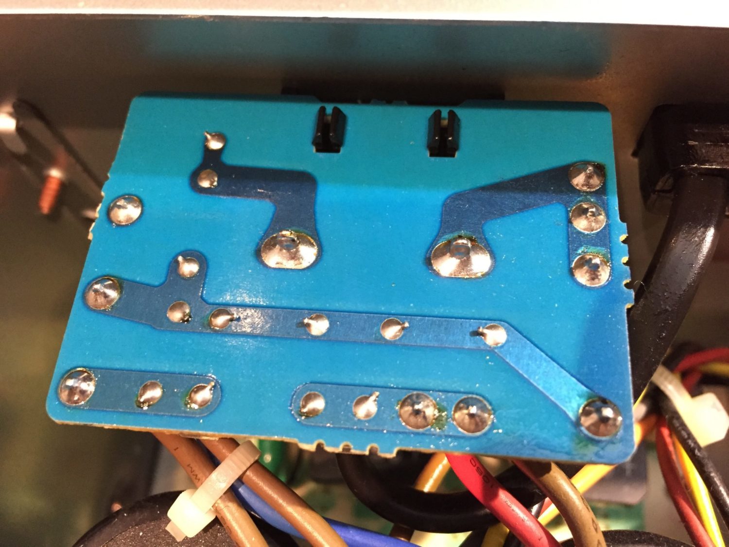
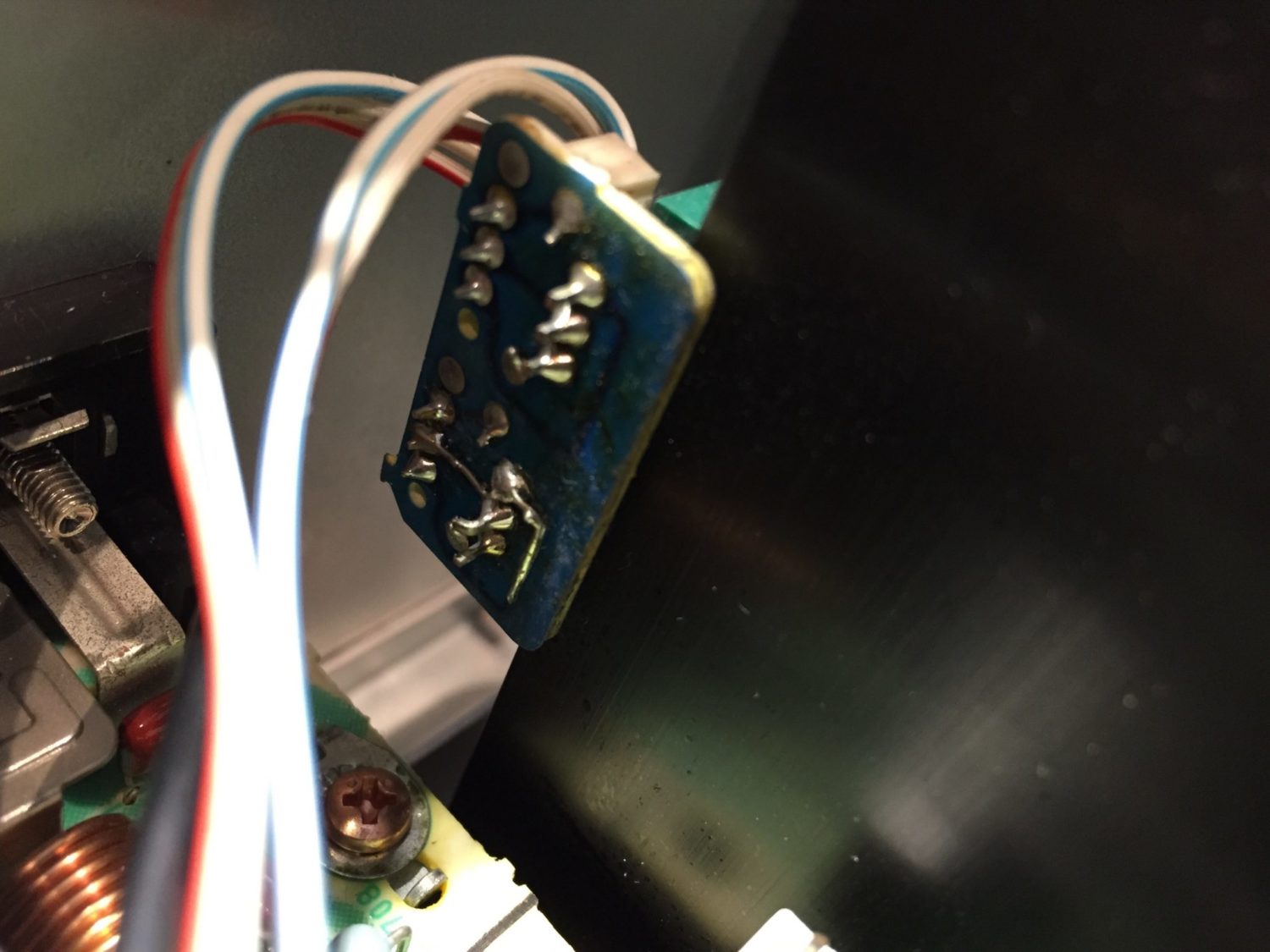
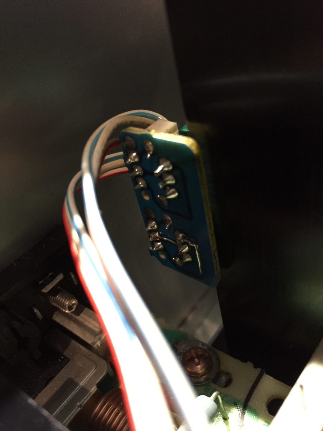
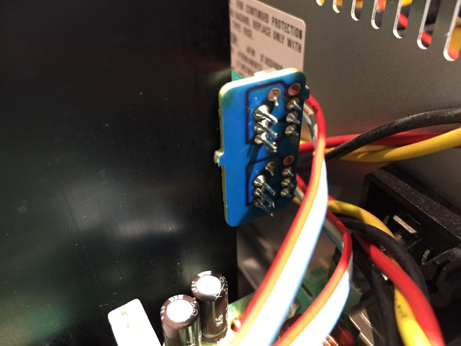
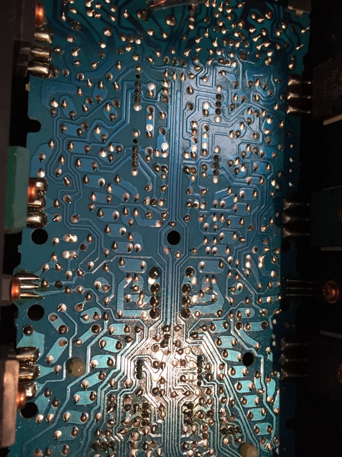
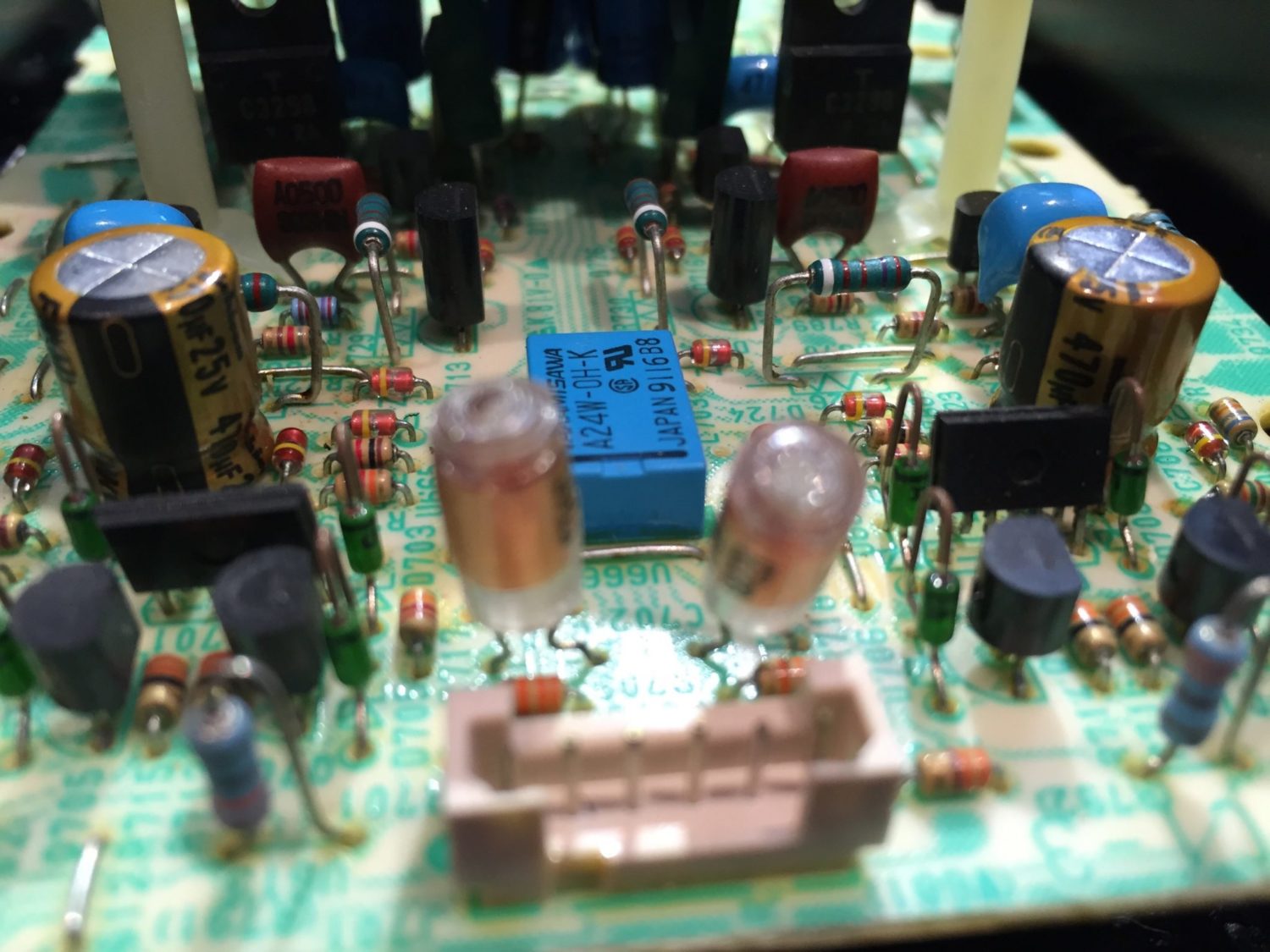
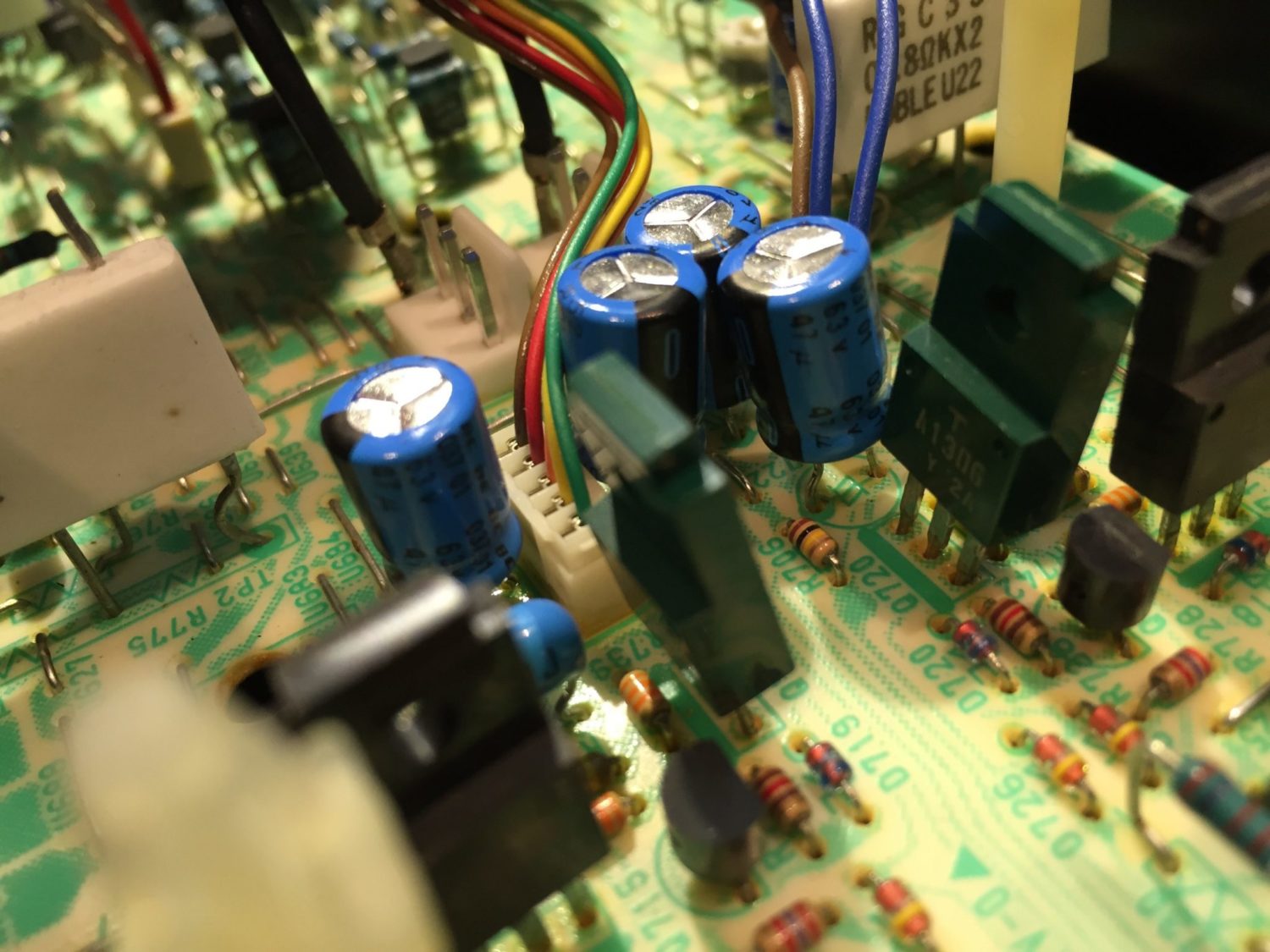
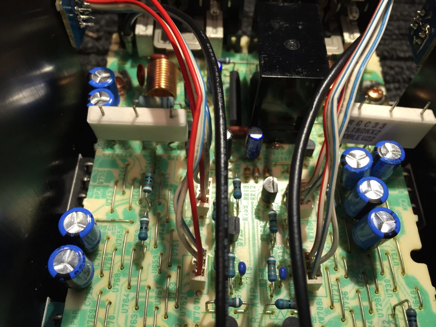
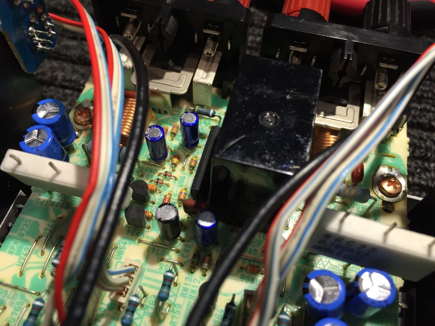
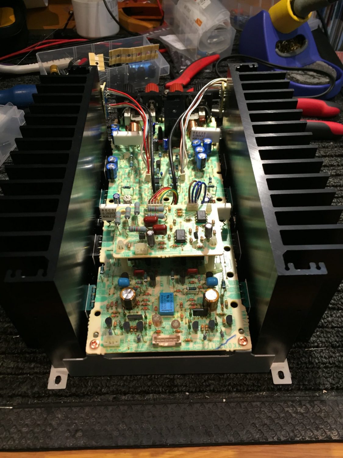
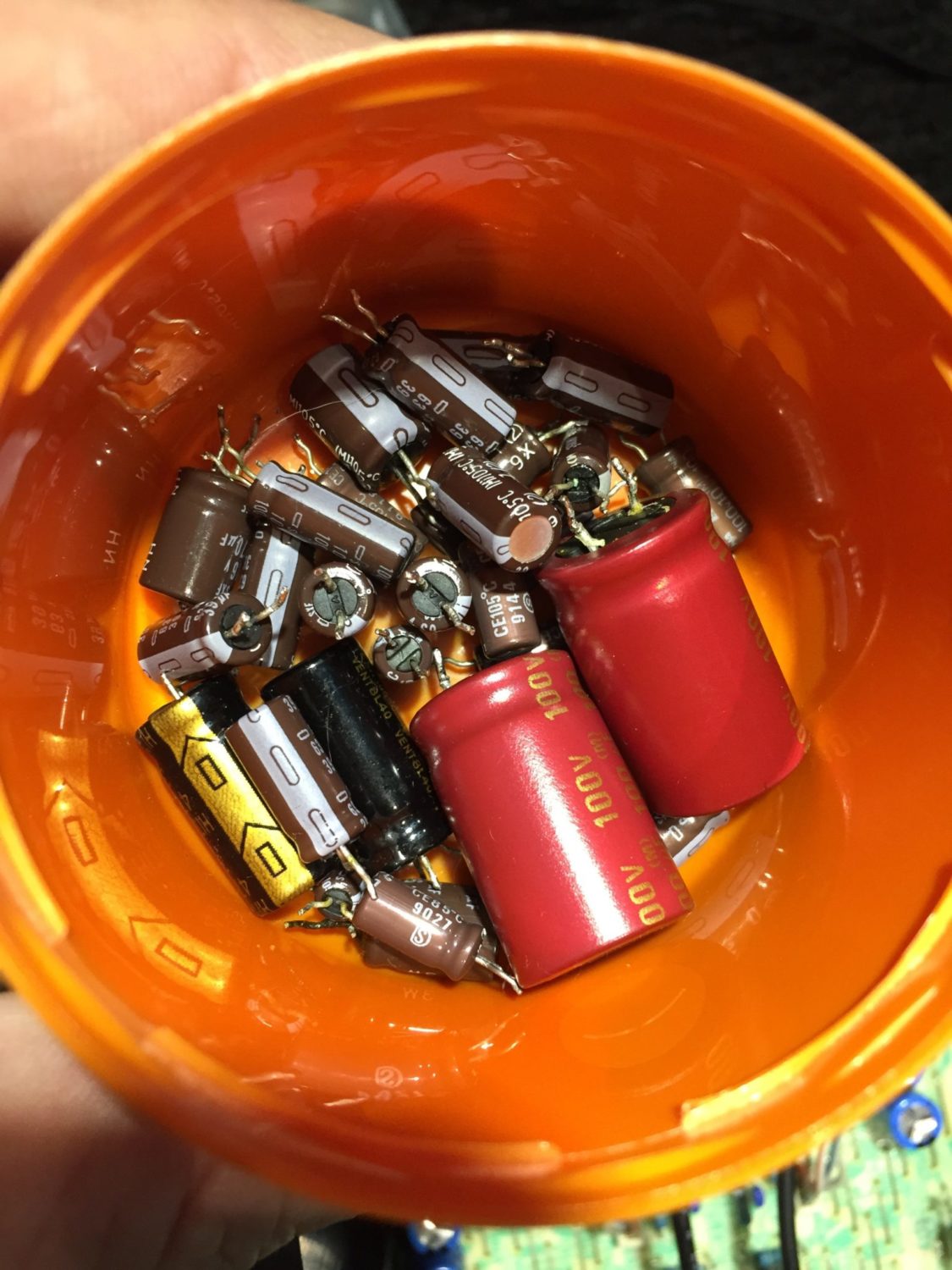
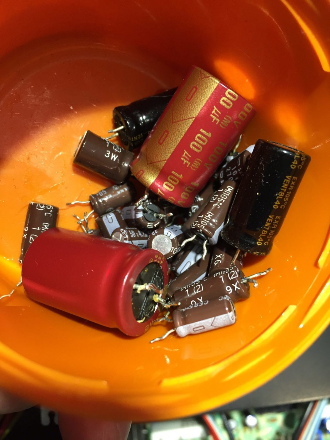
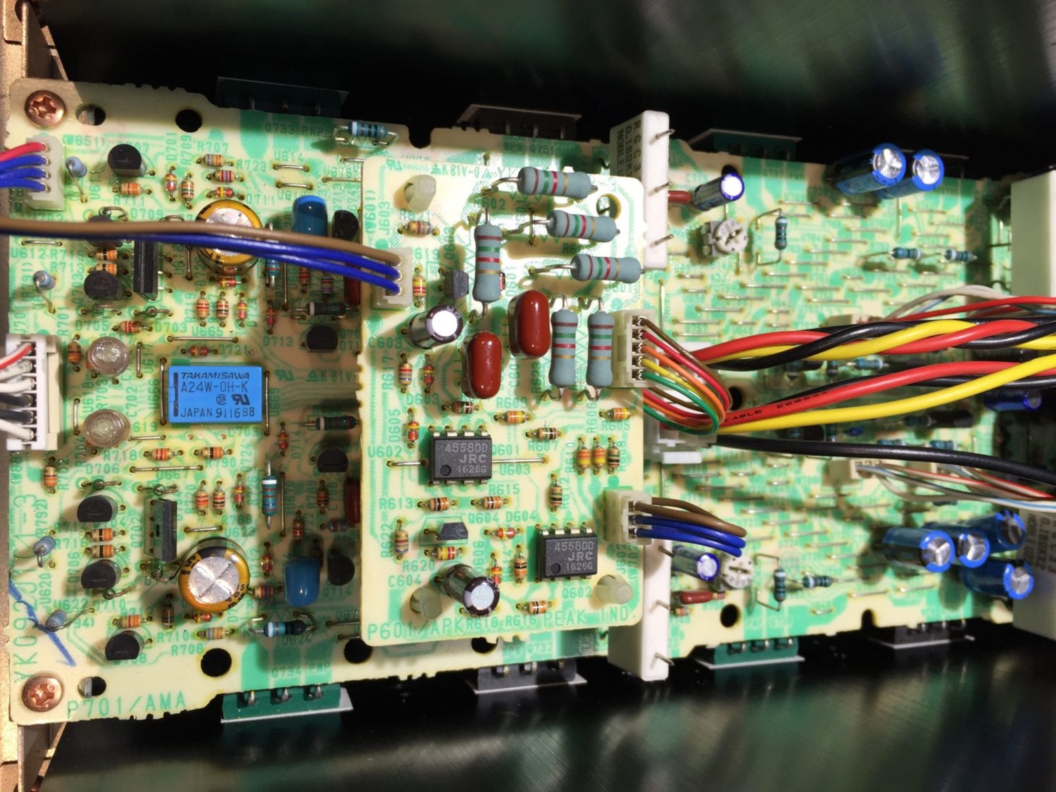
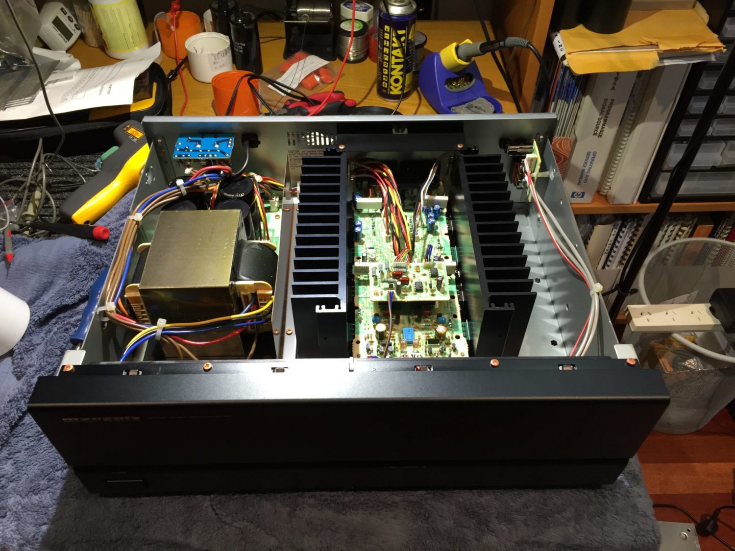
I proceeded to remove the amplifier module from the chassis, a job made easy by the excellent attention to detail and serviceability elements built into the design by Marantz engineers. With the amplifier module removed, I inspected the protection relay. This seemed good. The next step was to remove and replace each electrolytic capacitor on the output module, the peak indicator and the secondary power supply module.
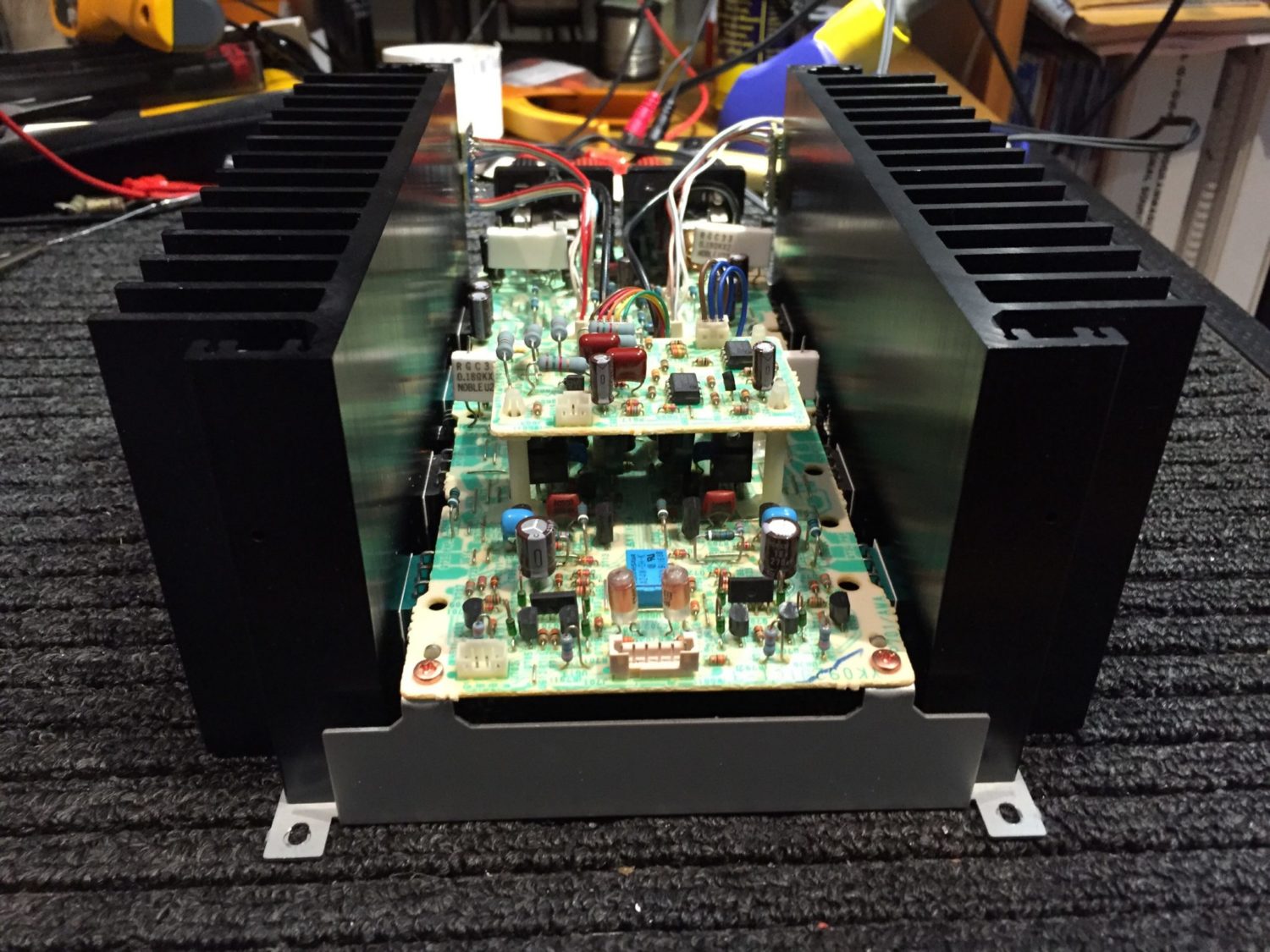
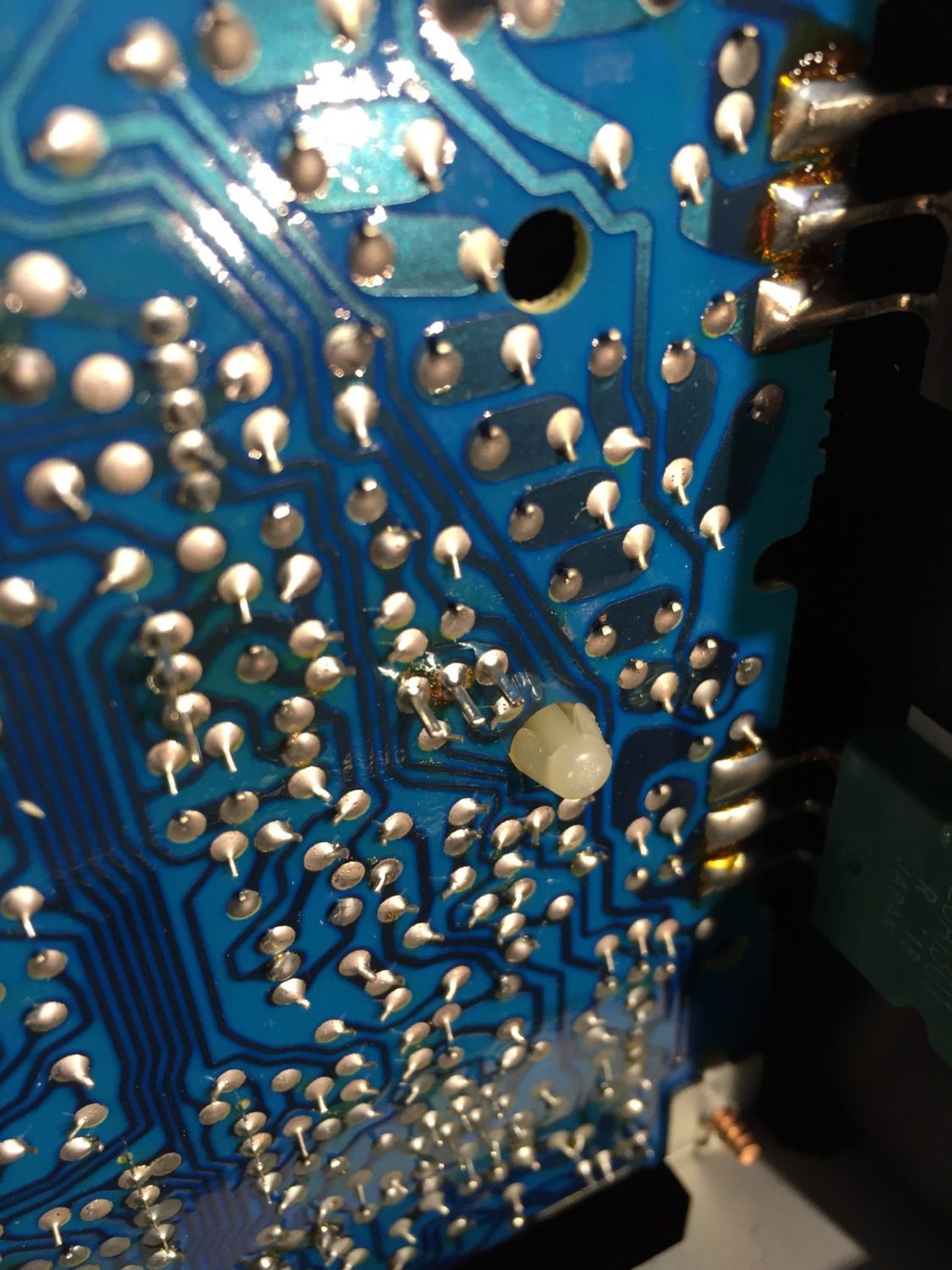
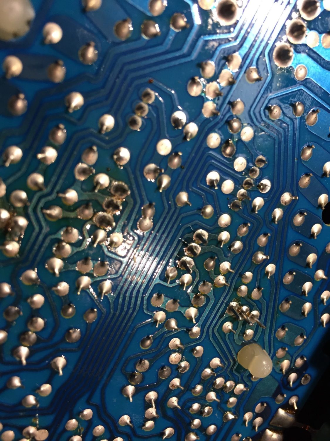
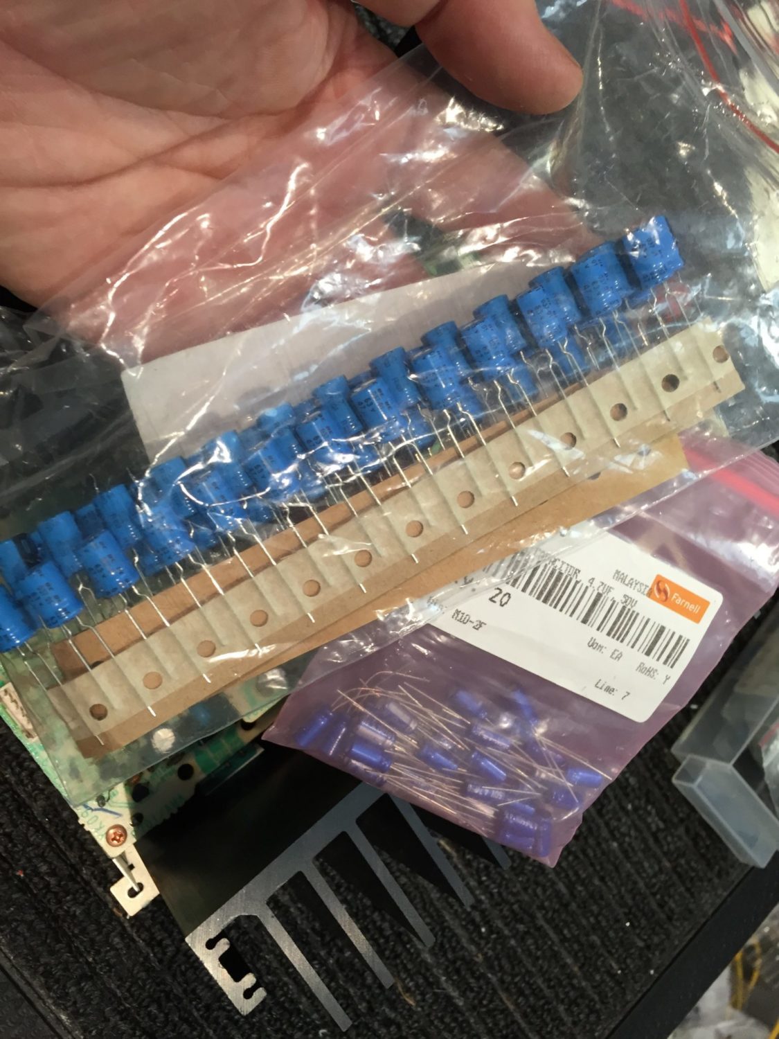
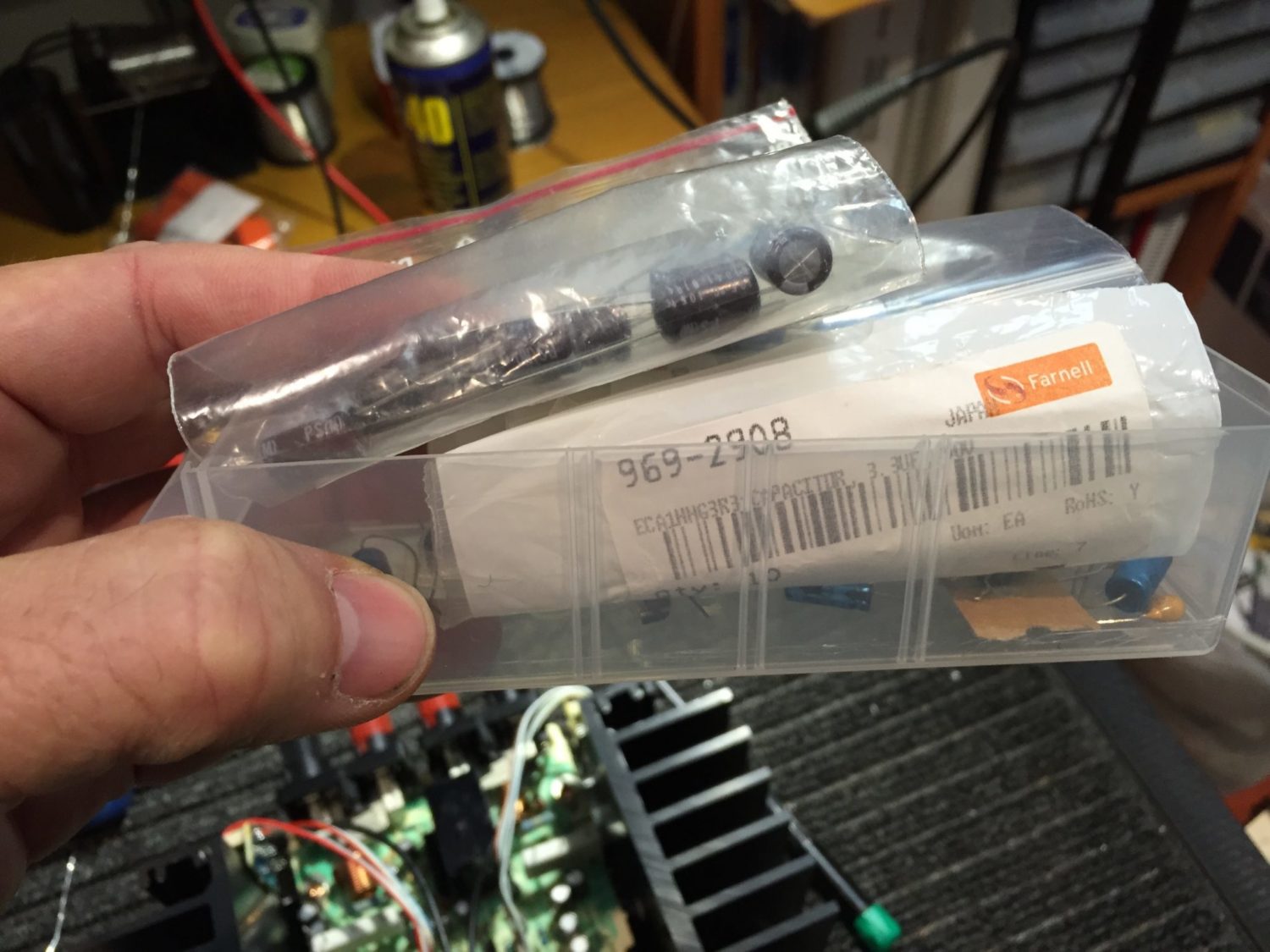
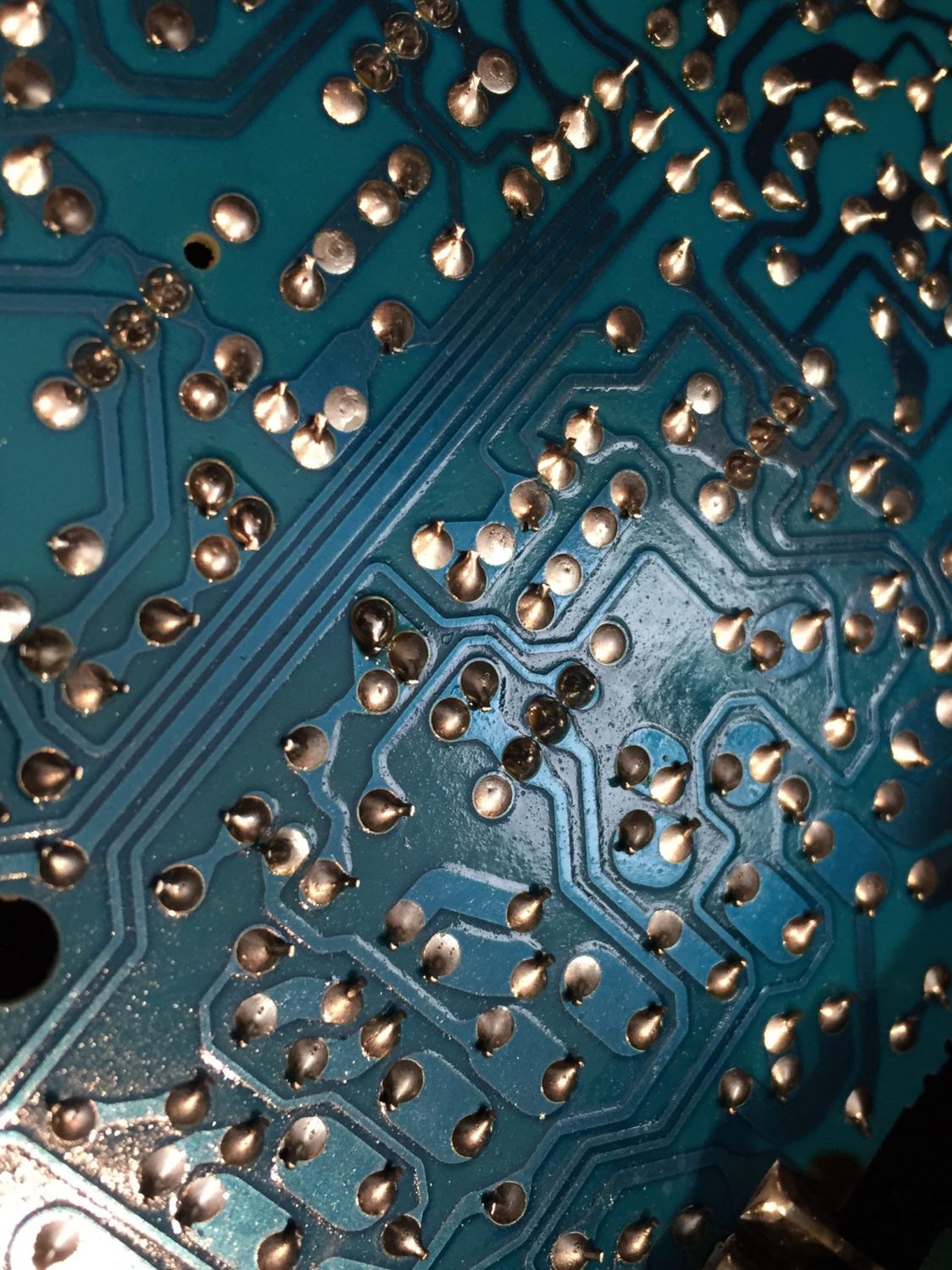
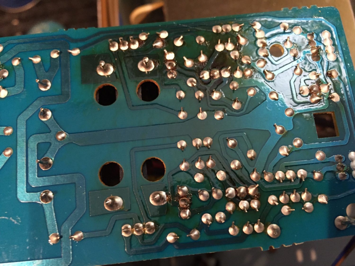
The work was difficult as the main amplifier PCB traces were even more reluctant to stay attached to the cheap substrate and I had to recalibrate my soldering temperatures several times from their already very modest settings! To be frank, I don’t lift traces, so to find them peeling off at 290 degrees was disturbing. In the end, though, all the work on the mainboard was completed without too much drama and some high-quality audio-grade capacitors and 105 degree rated parts now grace the restored amplifier board.
Power Supply
The next job with this SM-80 was to refurbish the secondary power supply, which actually feeds much of the amplifier with two additional rails – an 82V rail, and a 62V rail. The main power supply feeds the output devices and a few other areas like the protection circuit and generates +/- 55V rails. The secondary supply is located behind the front panel and runs pretty hot.
As with the mainboard, there were distinct signs of heat damage. Replacing these capacitors was straightforward as the board pops out for ease of servicing. I used two gorgeous Panasonic FC ultra-low impedance, high-temperature capacitors here, to replace the already very nice Elna Cerafine caps used by Marantz. The rest of the capacitors were replaced with various high-temp, low ESR parts I use in all my work.
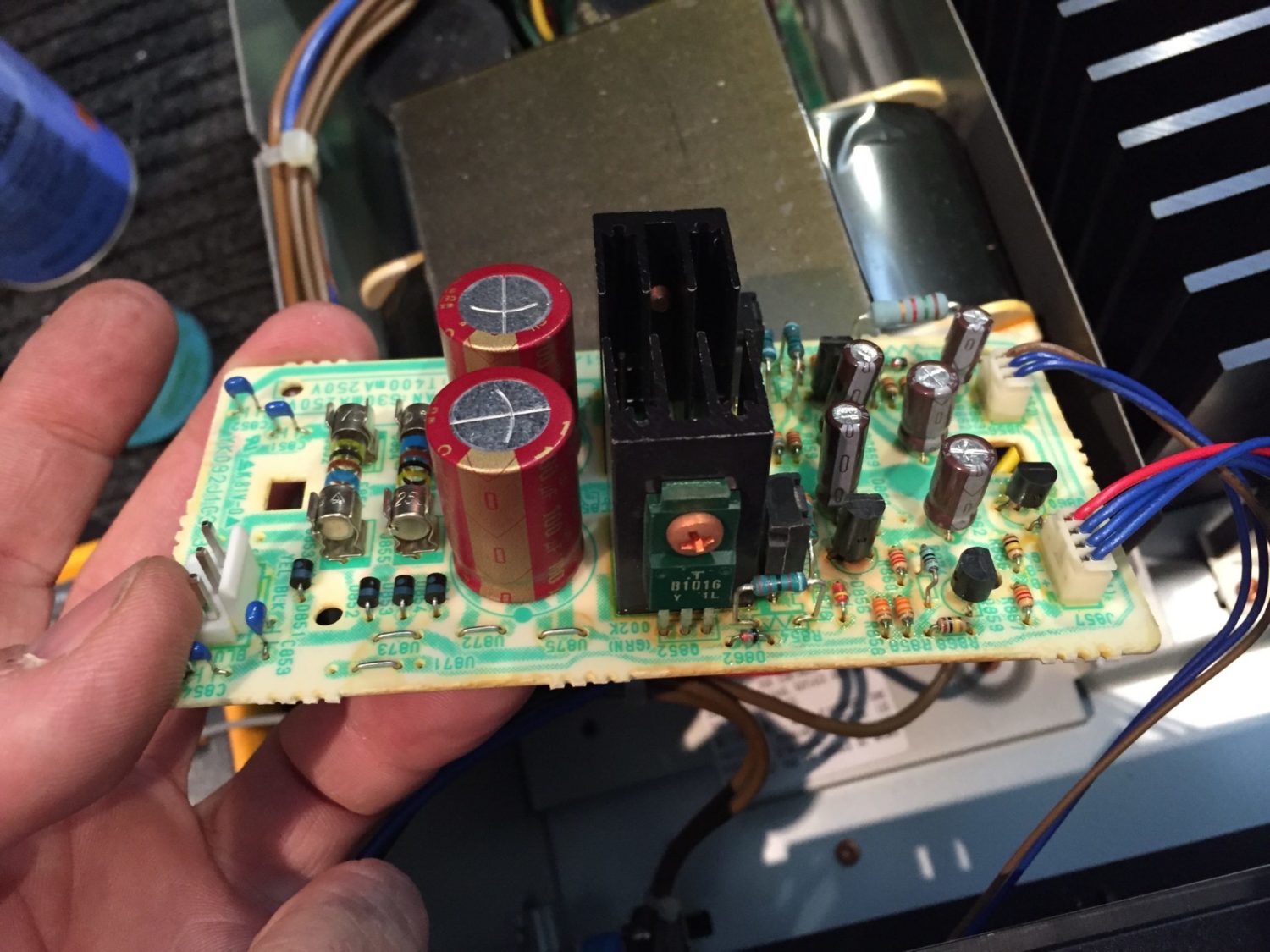
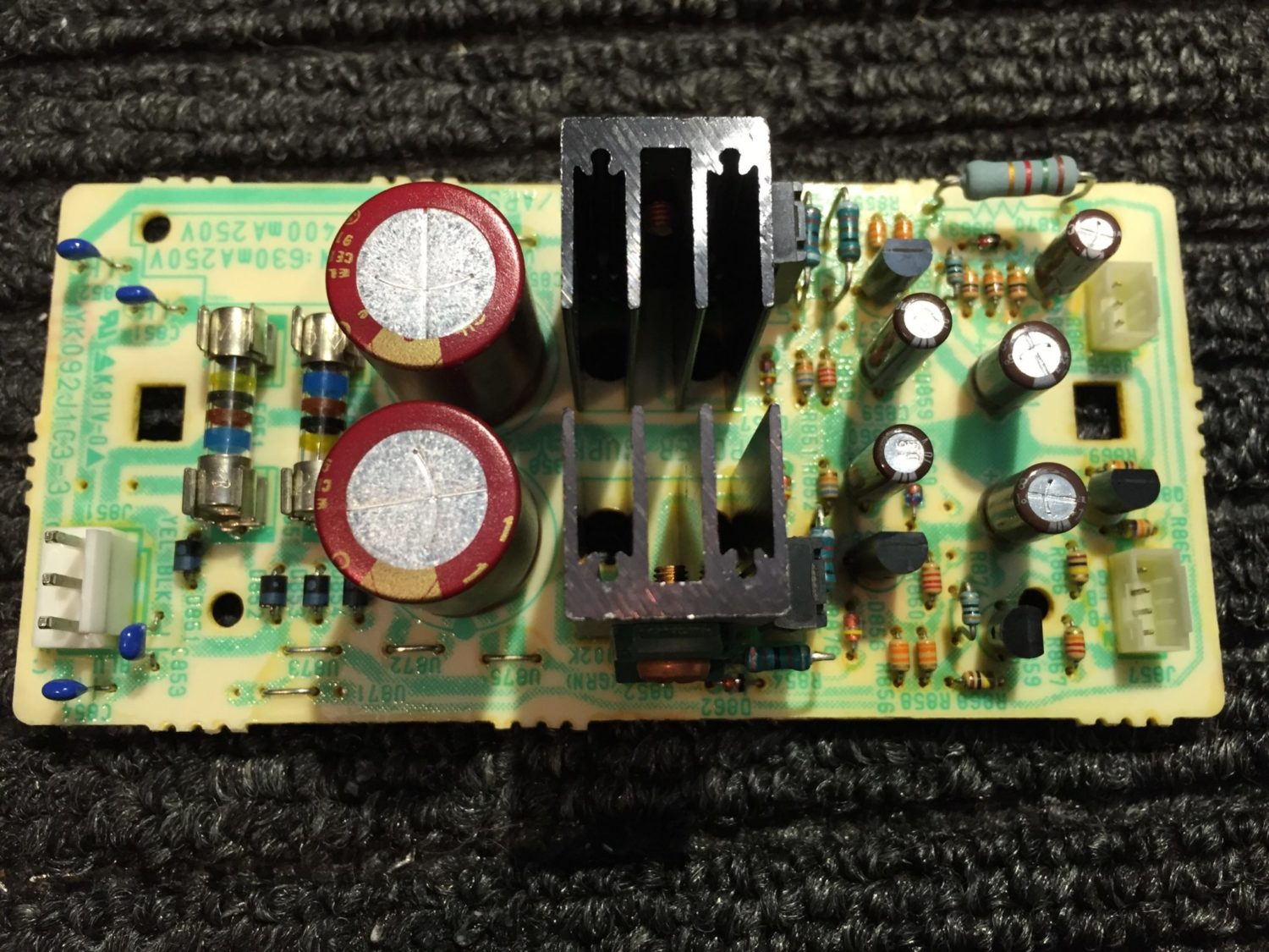
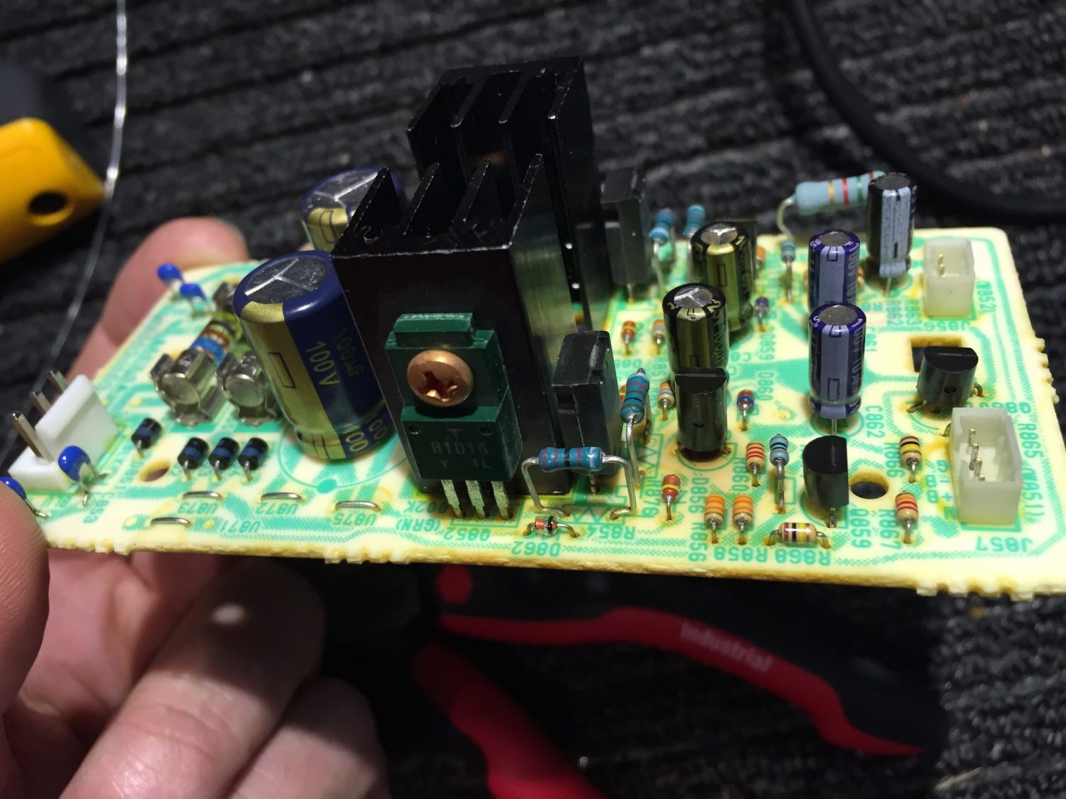
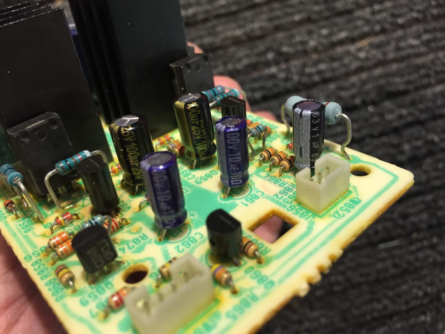
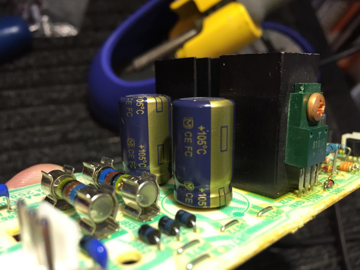
After reworking and parts replacement, I de-fluxed each board and checked for the correct orientation of parts. Next, I then hooked up the board to board interconnects and powered her up, hoping to hear that lovely protection circuit relay click closed, but nothing! I took the opportunity though to test other amplifier functions and found both channels to be working perfectly. I set the bias in both channels while looking at the schematic to try to understand why she was not coming out of protection.
Testing & Troubleshooting
After some investigation and testing, I found that a critical 55V rail was not appearing at a resistor feeding the protection circuit controller. The resistor in question divided the 55V down to 3V required by the TA7317P controller chip, but without any supply voltage, the protection circuit controller chip cannot operate.
In the end, I traced this fault down to a minuscule crack in a PCB trace near a capacitor I had replaced. This was invisible to the naked eye and I only found it by carefully probing the area with a multimeter and looking for breaks. Once I repaired this broken trace the amplifier came back to life. Woo hoo!
This brings up a point I made in the Marantz SC-80 overhaul article about the possibility of damaging traces when replacing parts. Despite being perhaps the most meticulous solderer, this hairline crack held things up and was invisible to the naked eye. Even under magnification, it was barely visible. This highlights the need for care when replacing parts, especially when one suspects traces and board material might be poor.
This Marantz SM-80 is now working perfectly. She comes out of protection after about 5 seconds which is the correct time interval. After a complete recap, this SM-80 will provide many more trouble-free years.
Discover more from LiQUiD AUDiO
Subscribe to get the latest posts sent to your email.

Hi Mike
Roughly how much does it cost for a repair like this? I have a Hafler power amp that needs some work.
Paul
Hi Paul, thanks for your question. Every job is different so I can’t really give you an estimate until I inspect the amp and figure out what is required. The Marantz needed a fair bit of restoration work and this pushes up the cost. Much depends on the number of parts that need to be replaced. Kind regards, Mike.