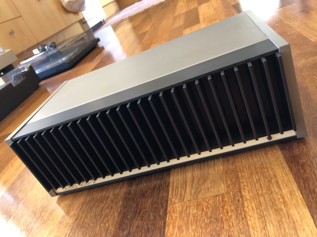
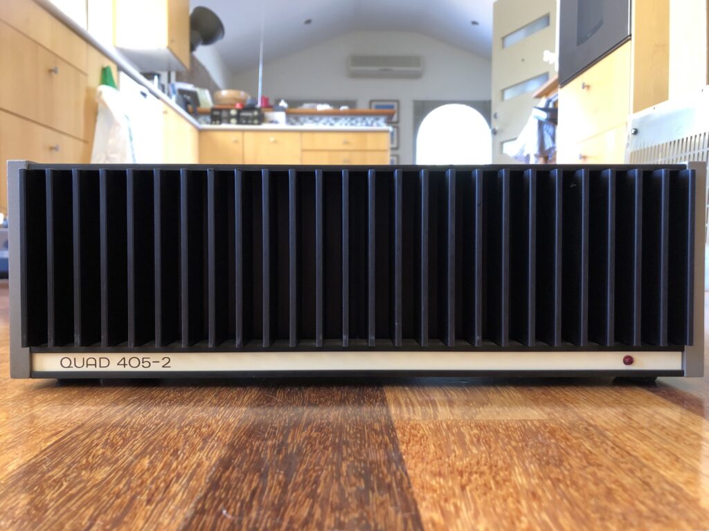
Come along as I overhaul and upgrade a beautiful British classic, the Quad 405-2 power amplifier.
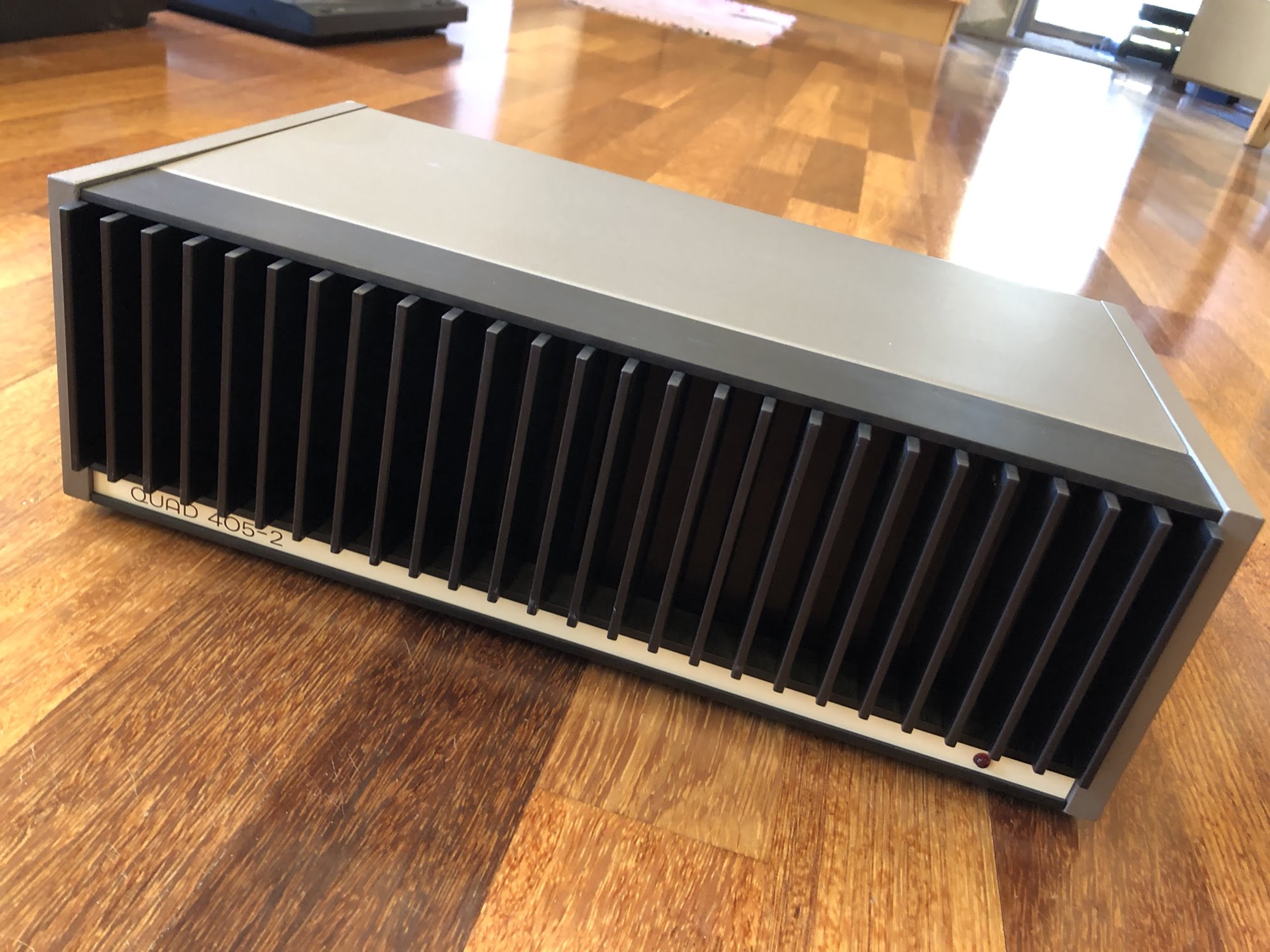
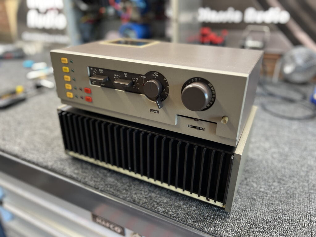
The Quad 405-2 is still revered, some 40 years after its release. These are truly special amplifiers, don’t let the understated English looks fool you. What almost all of them need however is work, so come along for this Quad 405-2 Power Amplifier Restoration as I walk through some of what I cover when I do this sort of work.
UPDATE: Revised with additional information, in 2021!
For some extra reading, check out my Quad 405-2 review, Quad 405 refresh, and Keith Snook’s Quad 405-2 page.
Quad 405-2 Design
The amplifier we are looking at here is a Quad 405-2, but the previous 405 and 405-2 are similar. They are masterpieces of thoughtful, understated design and showcase the less-is-more approach of Quad’s legendary engineer, Peter Walker.
I can’t think of a mainstream commercial amplifier with fewer parts than the Quad 405. Yes, there is an op-amp in the front-end to keep the parts count down, but the driver stage is just two TO-220 devices operating in class-A. The output stage is another two N-channel TO-3 devices per channel. No complimentary pairs here!
The driver and output transistors are thermally coupled to a block of aluminium and board-mounted, eliminating wiring. Add a sprinkling of passive components of very high quality and you have the elegant simplicity that is the Quad 405 amplifier module.
Restoration
I tend to utilise a less-is-more approach to my work, avoiding senselessly replacing perfectly good parts. Quad used excellent parts in most places and most are perfect, so why change them? To that end, transistors, resistors and most other parts remain stock.
This 405 needed some TLC, despite the seller telling me it was ‘restored’. I was keen to see what that actually meant, but it turns out it means something very different to me. This amplifier was not restored and needed a full overhaul. On top of that, the amp was damaged during shipping. I made a claim through eBay and was refunded most if not all of the original purchase price, a good result.
Apart from that, this unit has two different amp modules, one revision apart. Quad made something like 10 revisions of the 405/405-2, improving them as they went. This is of no real consequence in a dual mono amp like this, and I’ve since acquired and installed a matching revision module, but an original must have blown up at some point.
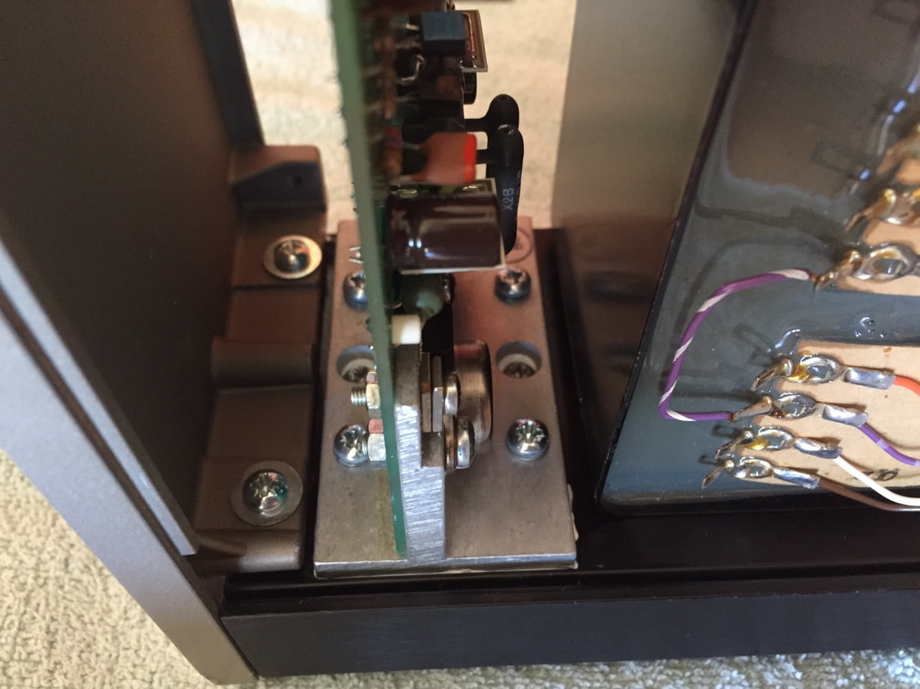
Quad had a simple repair policy – simply install a new module, job done. My amp contained a few original and dead caps, some old chewed-out screws and other bits and pieces that I decided to sort out. Let’s have a look inside…
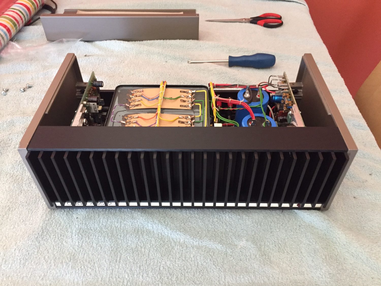
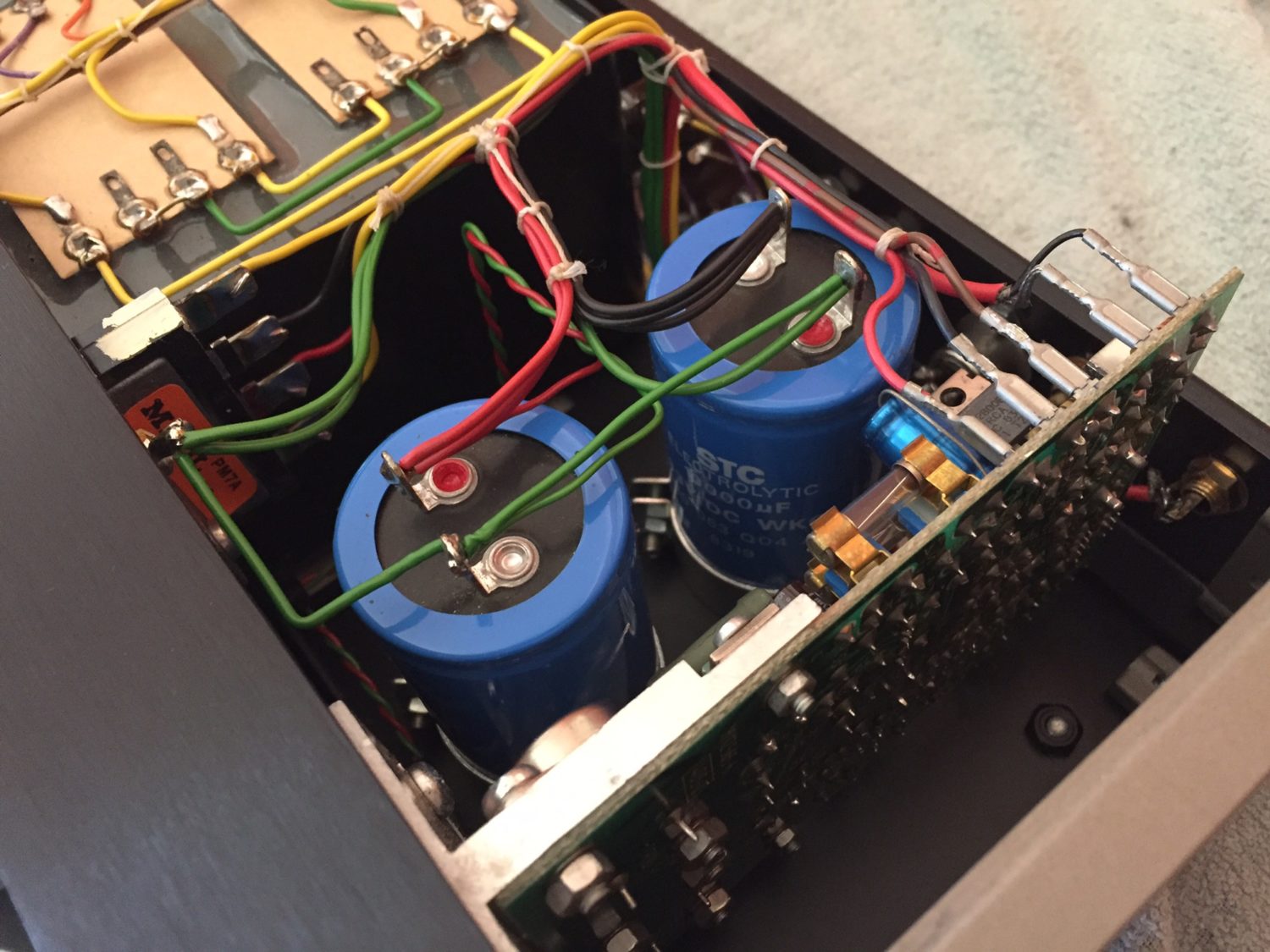
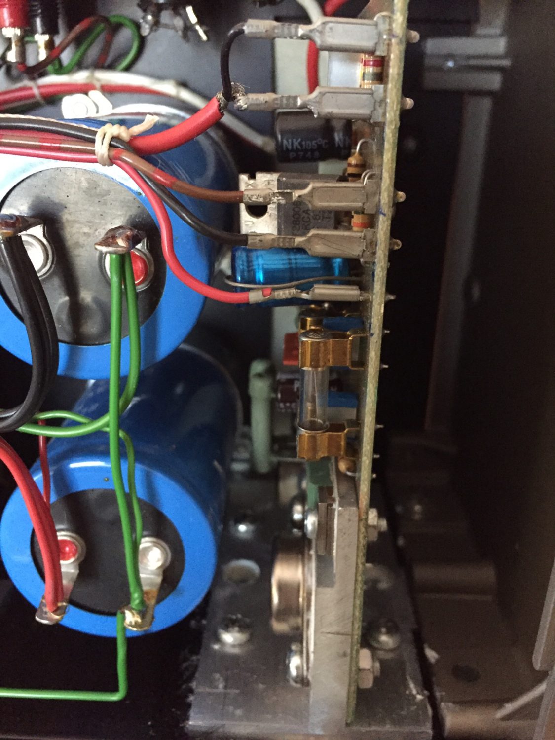
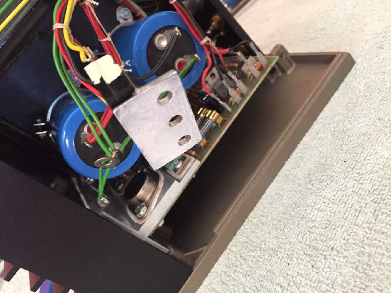
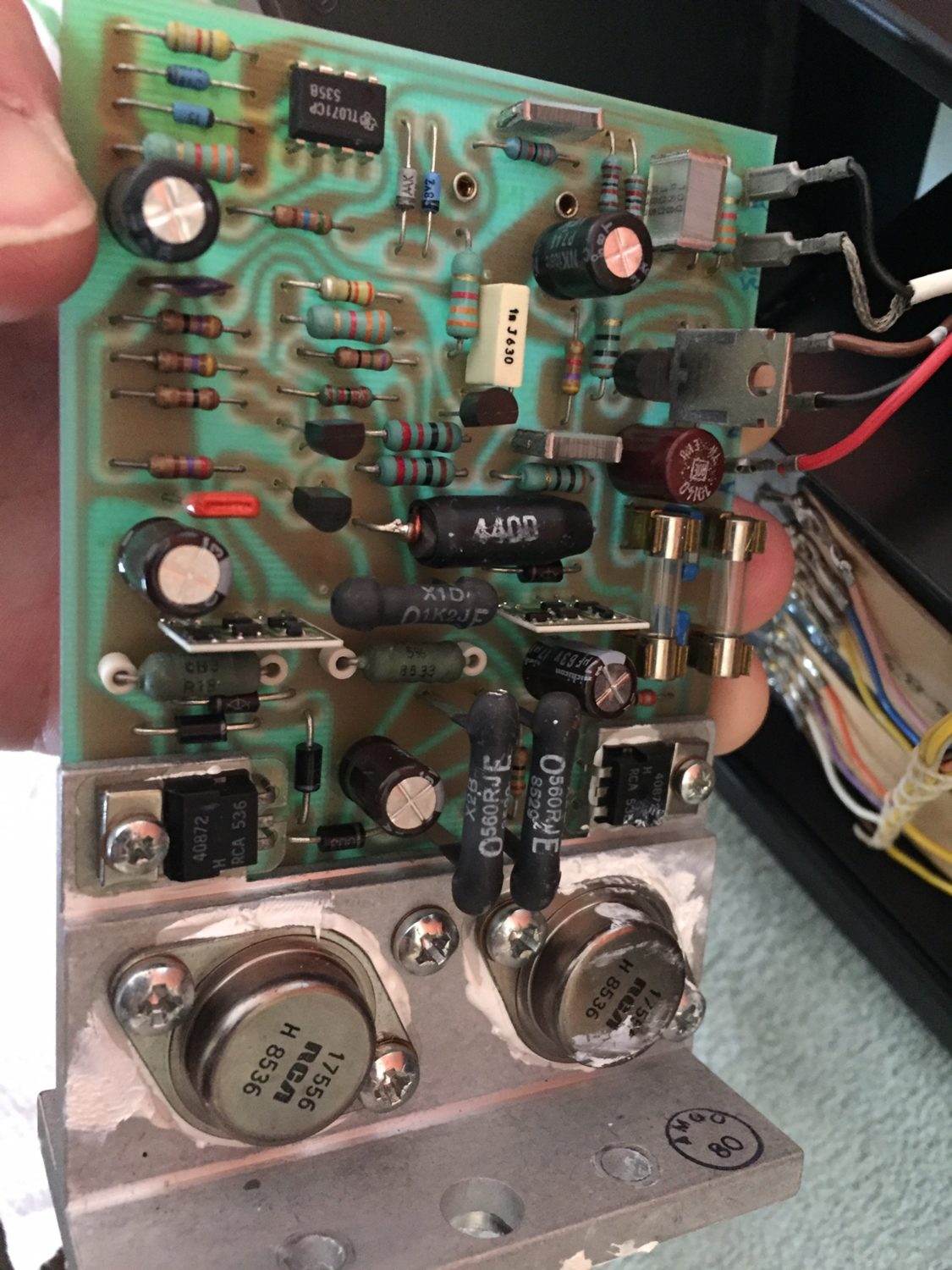
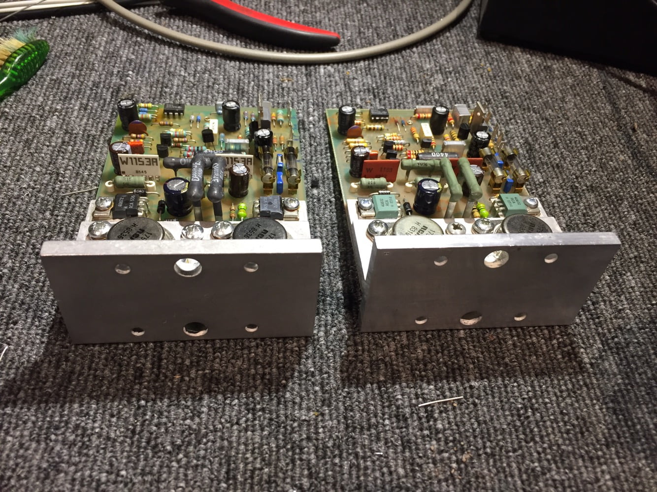
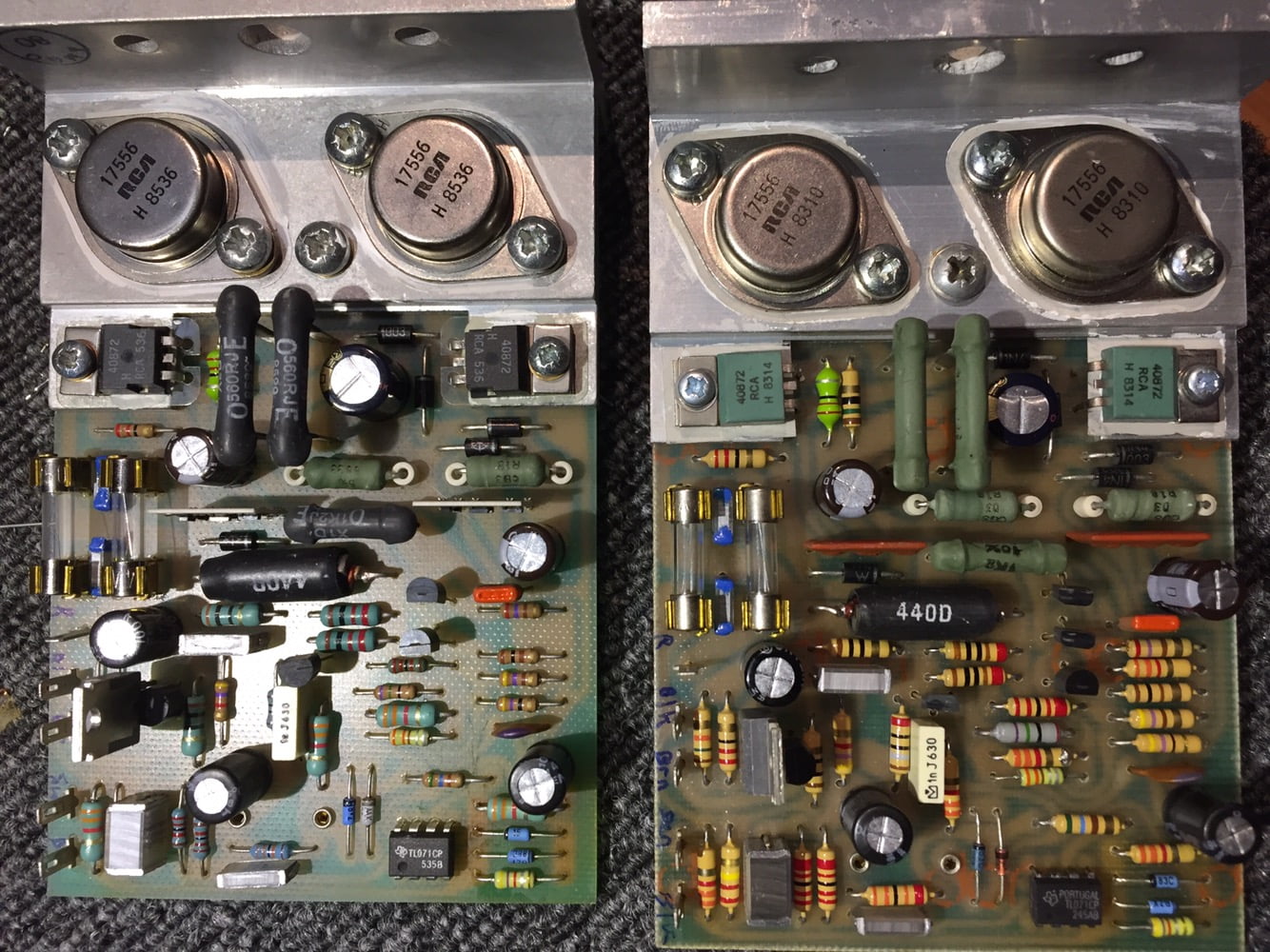
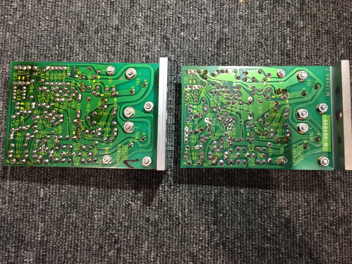
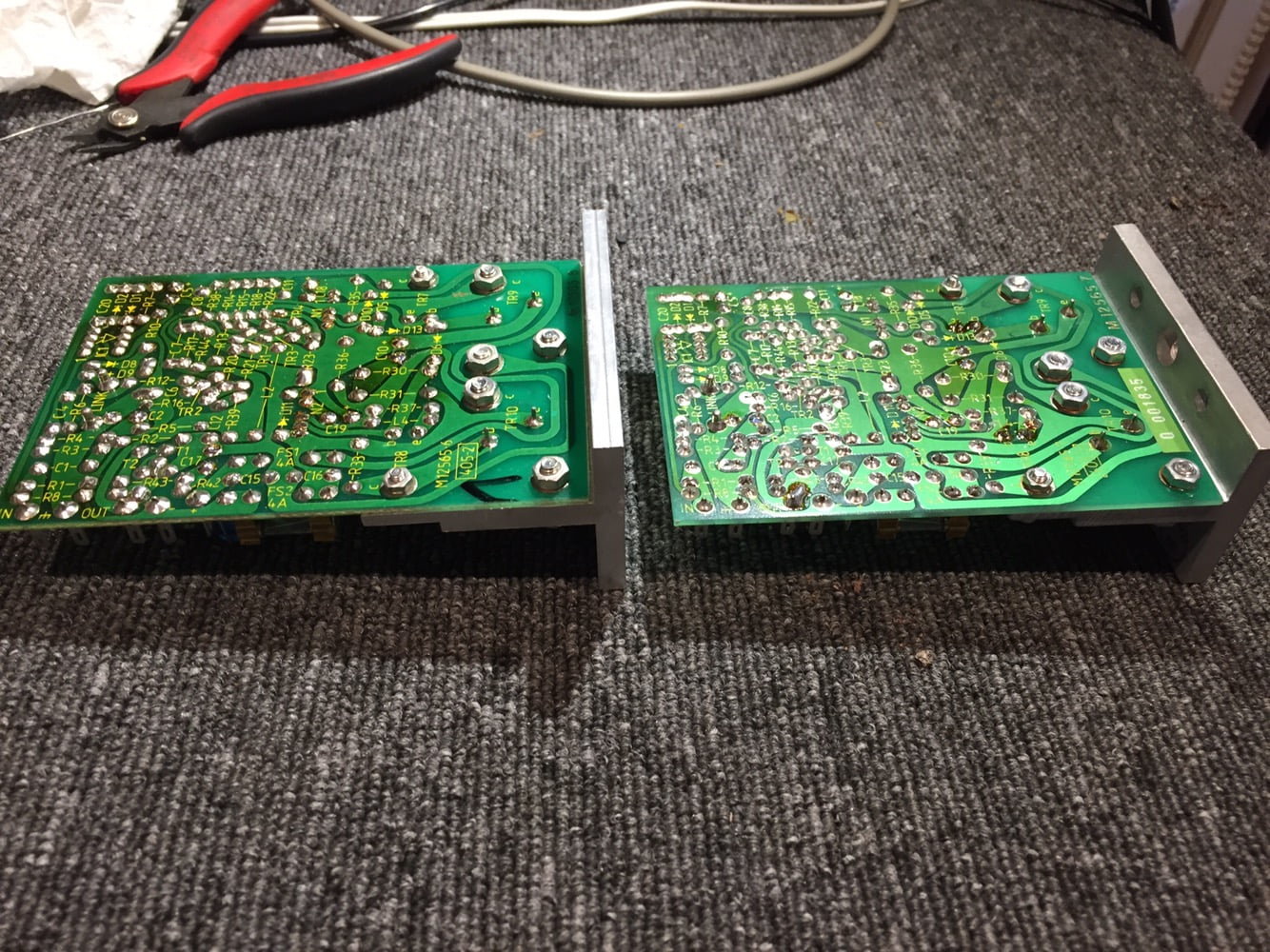
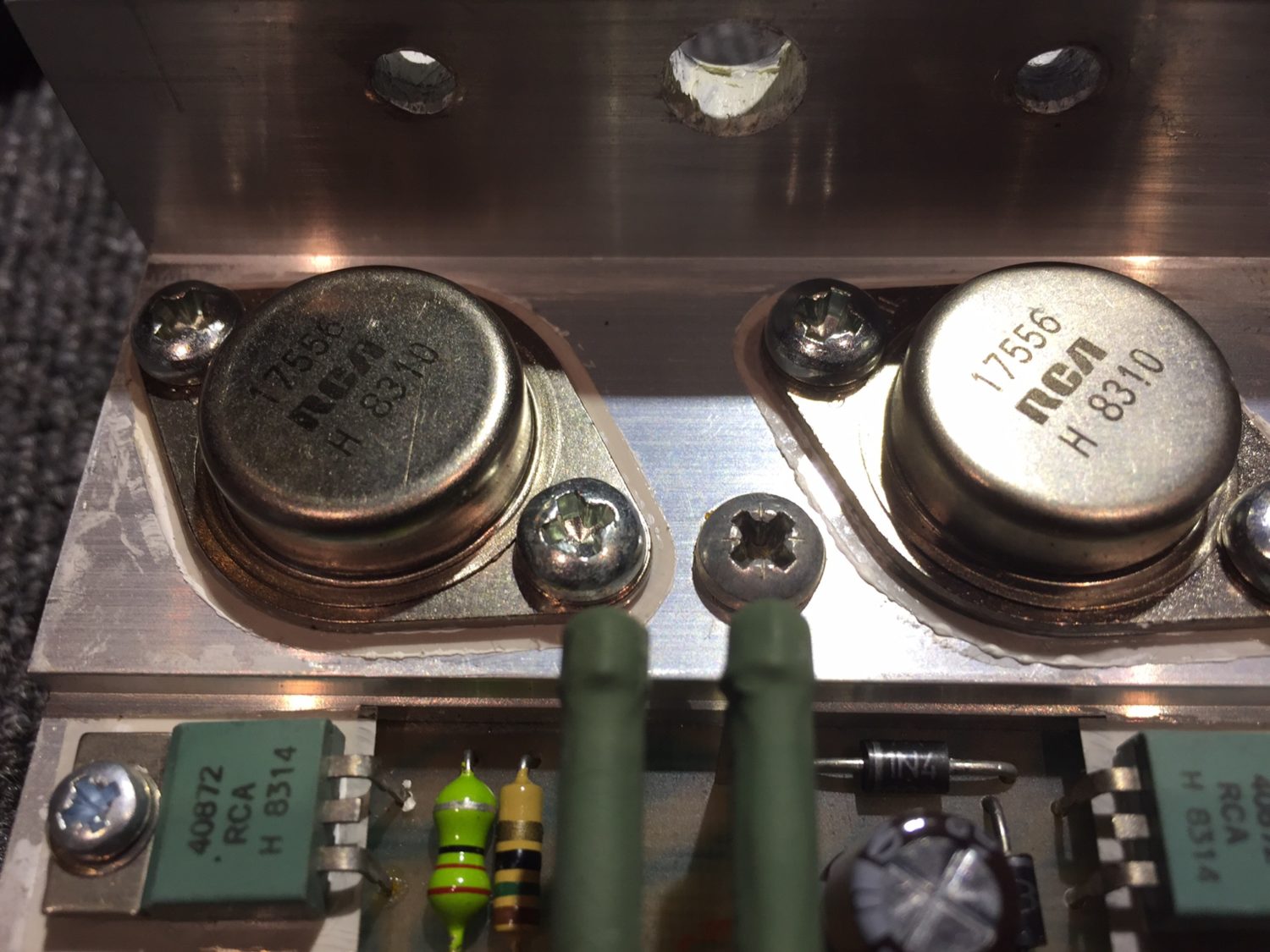
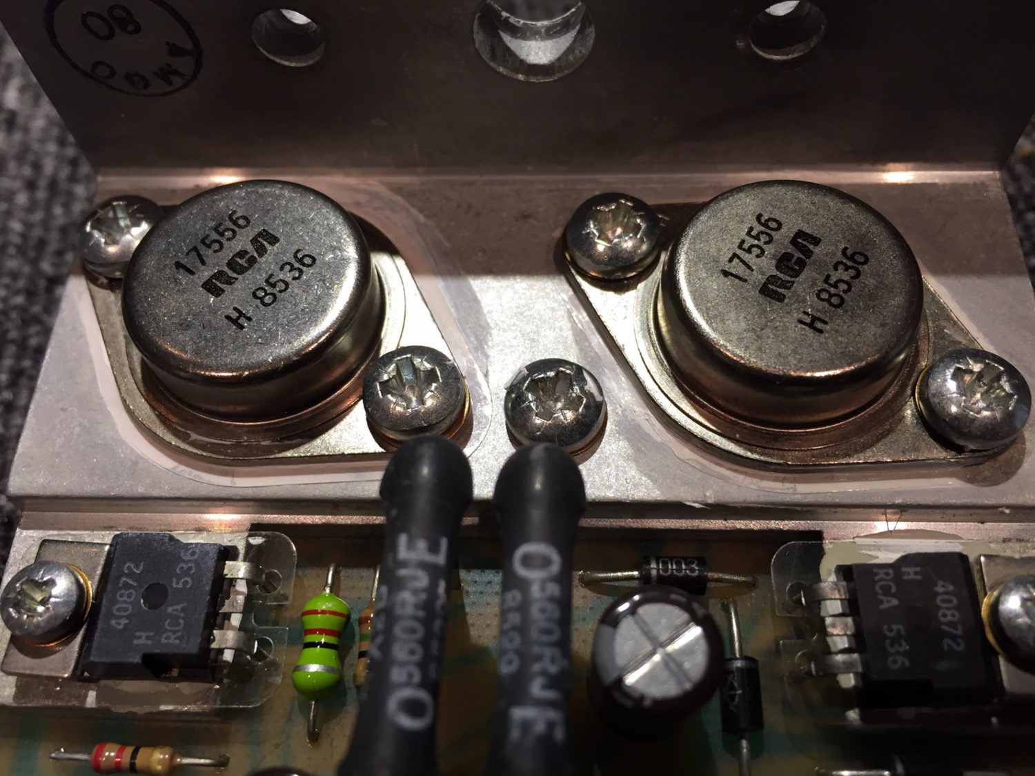
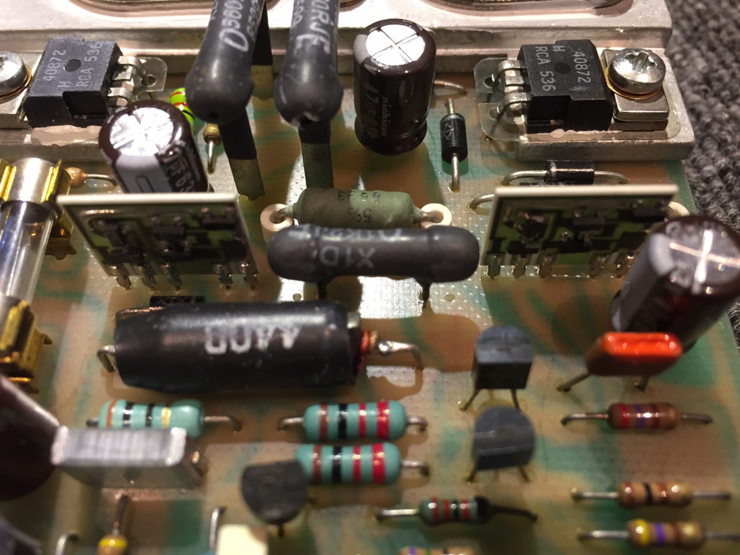
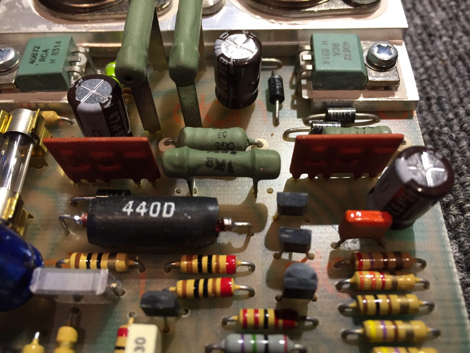
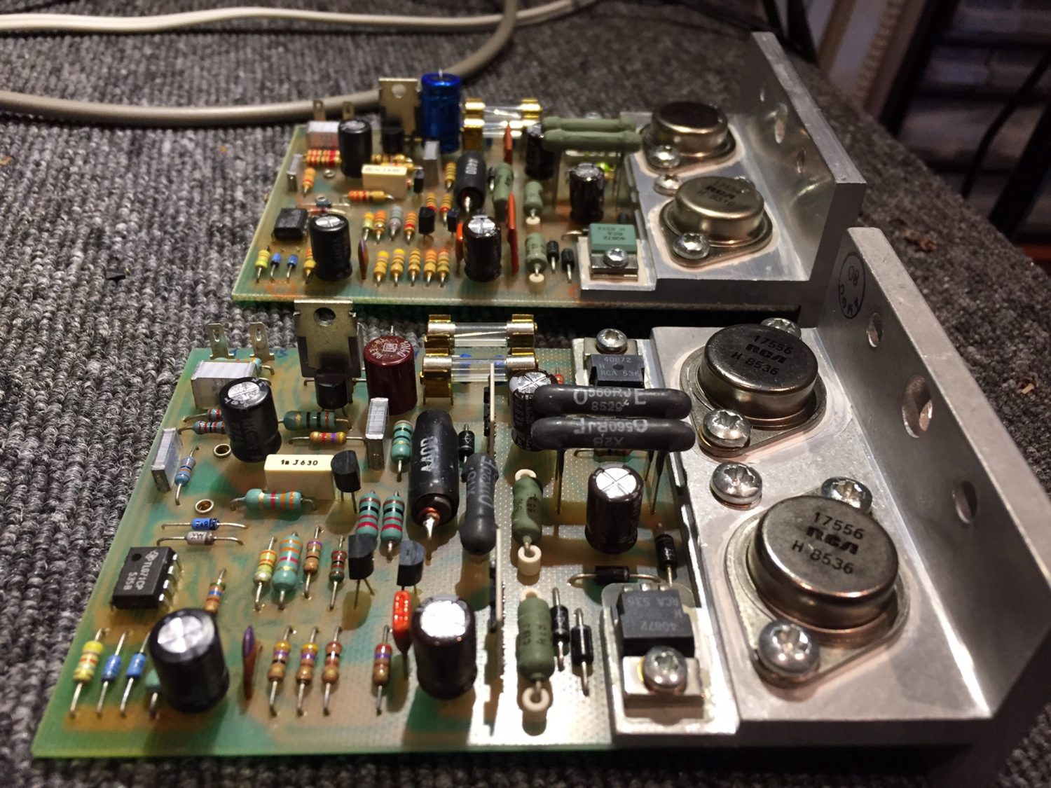
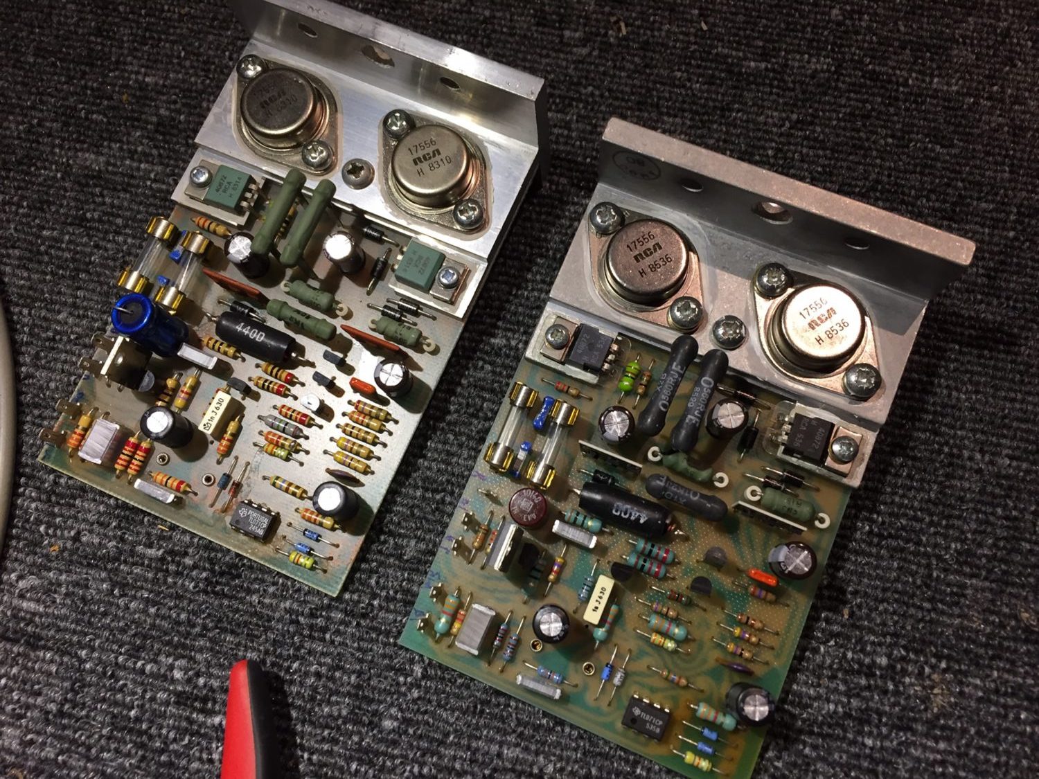
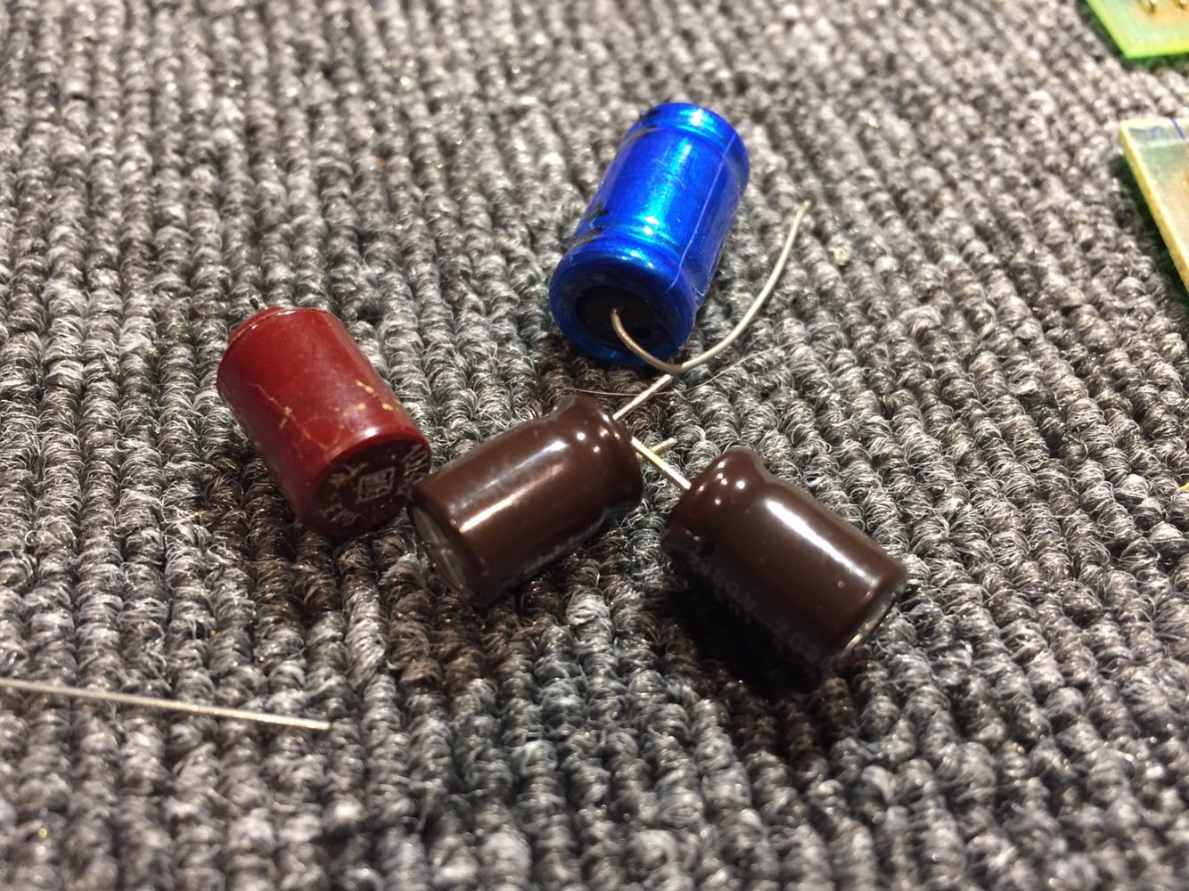
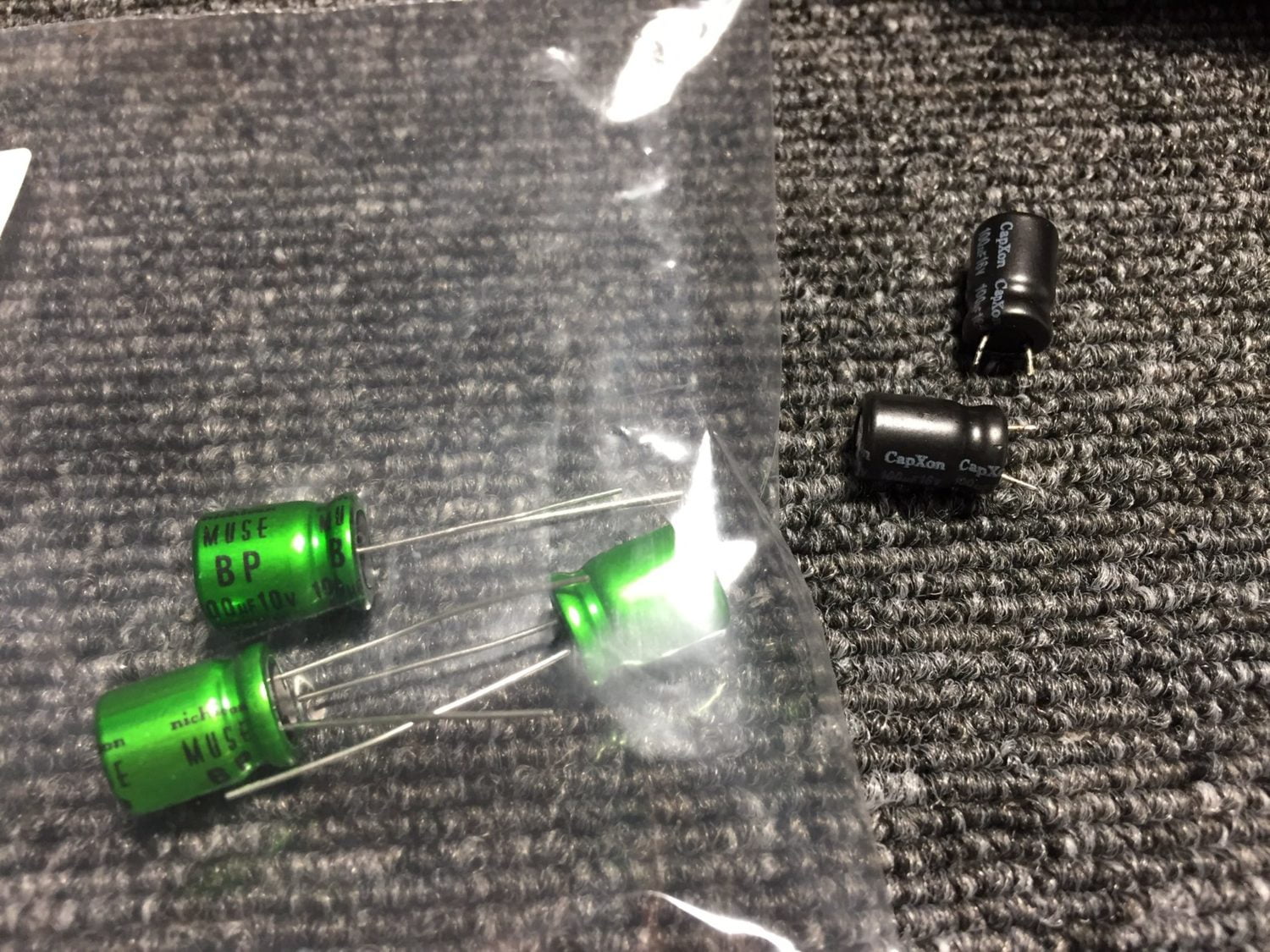
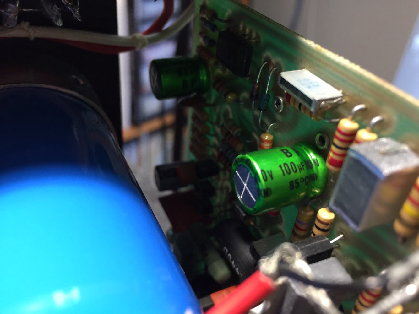
After completing this initial overhaul work, the Quad 405-2 sounded great. The 405-2 sounded much better after replacing the old board-mounted capacitors and generally tidying up the old girl.
Phase 2 – Additional Quad 405-2 Restoration & Improvement
I initially left the original TL-071 FET input op-amps in place as I wanted to baseline and characterise the first steps of improvement, so I could speak with authority about how each step influenced the sonic results and performance of the amplifier. As some will already know, I’m against the unscientific swapping of op-amps. It’s better, and smarter, to try to understand the reasons behind the choices originally made and then pick an actually better replacement, based on science.
There are several other improvements I’ve tested and now incorporate into most customer jobs. The first is to replace a few critical ceramic caps with polystyrene or silver mica 1% rated parts. The second is to replace the TL-071 input op-amps with the modern TL-2071 equivalent. Other FET input op-amps work as well and there are a couple of others I also use, with great success in more premium overhauls. I also now modify the ground scheme in many of the 405 and 405-2s I work on along with the RCA connectors. I upgrade the mains inlet and fit special film snubbers there and in other locations on the transformer and filter caps.
Filter Capacitors
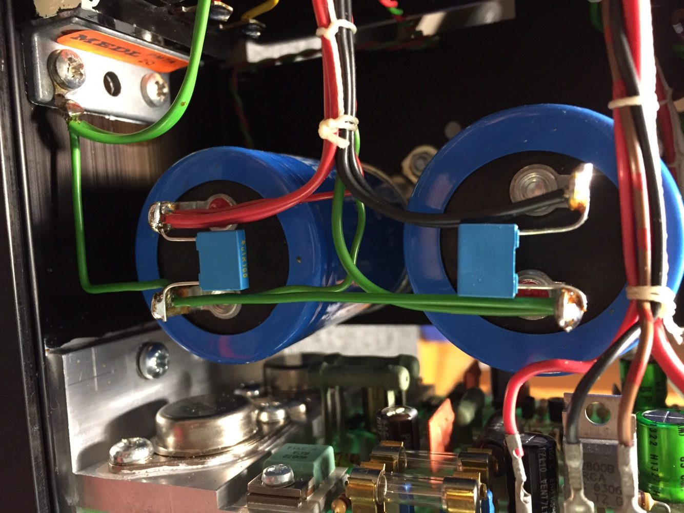
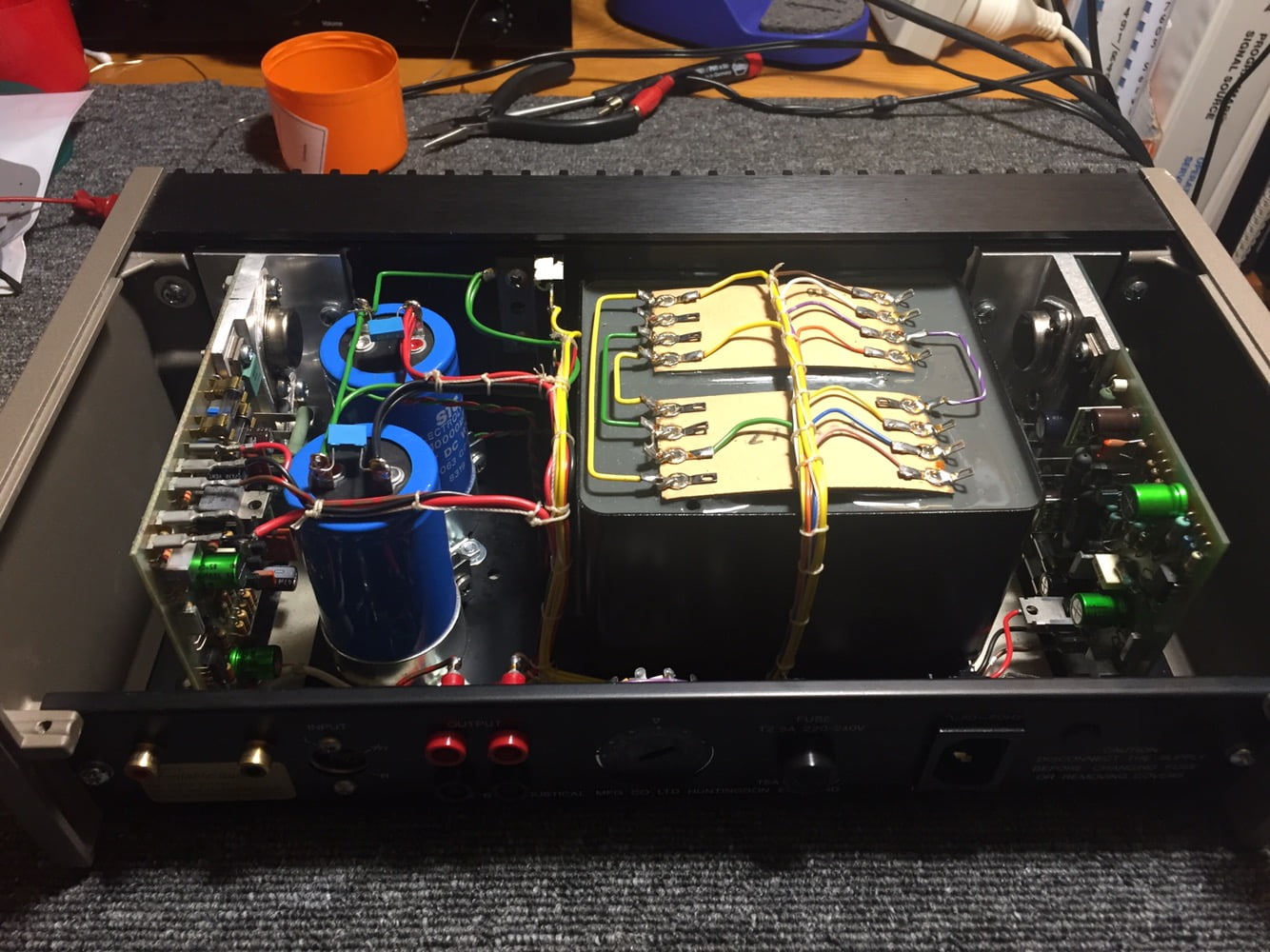
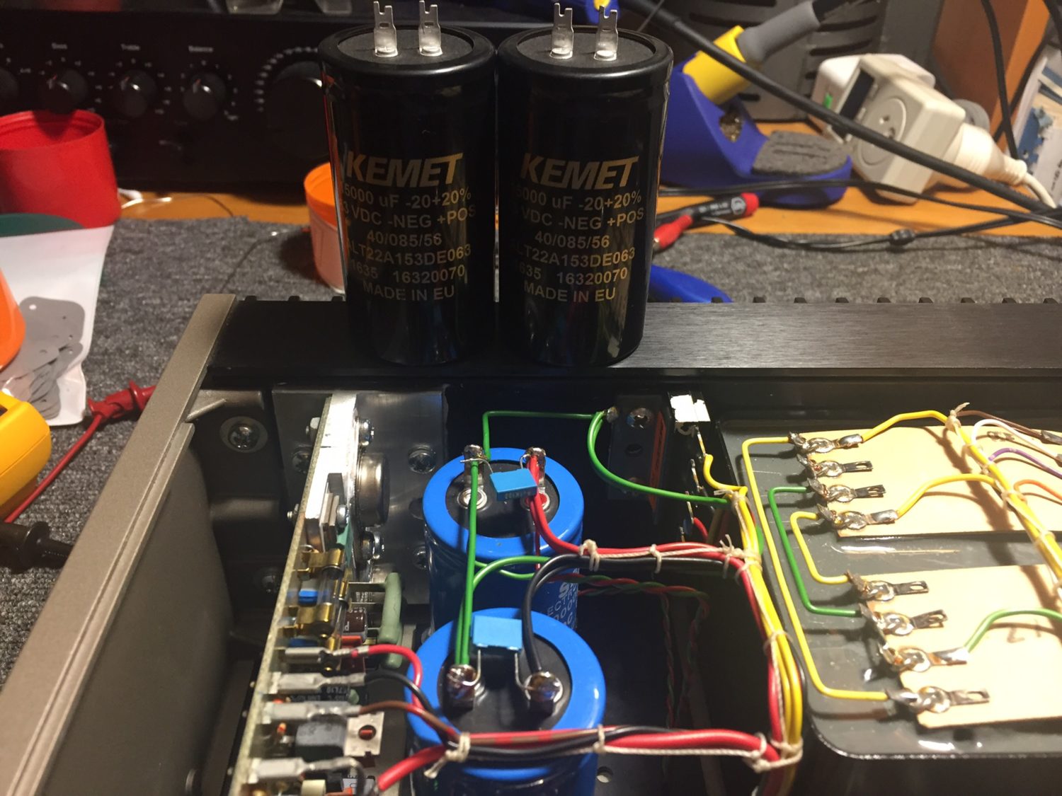
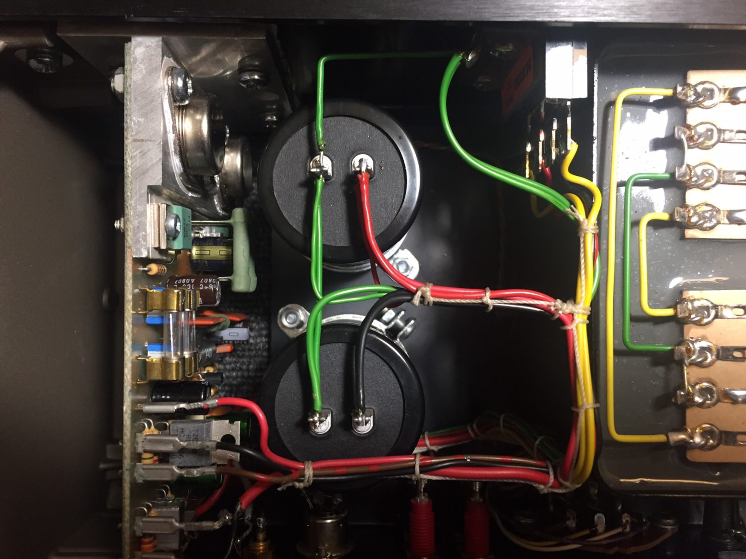
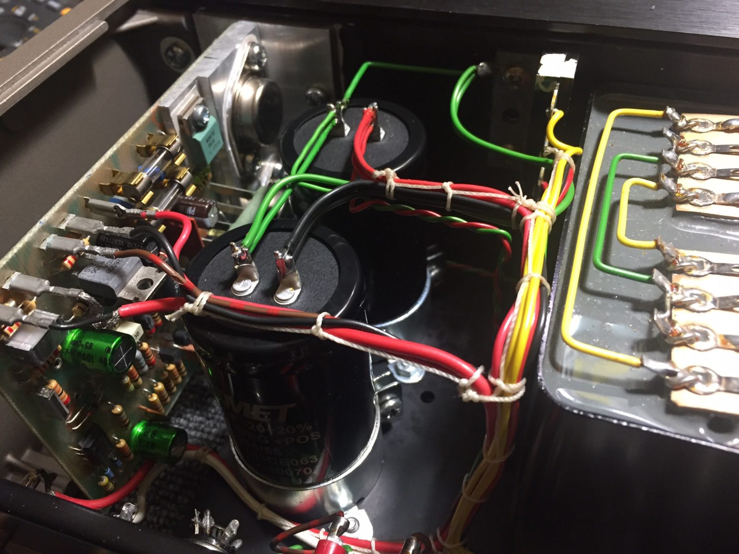
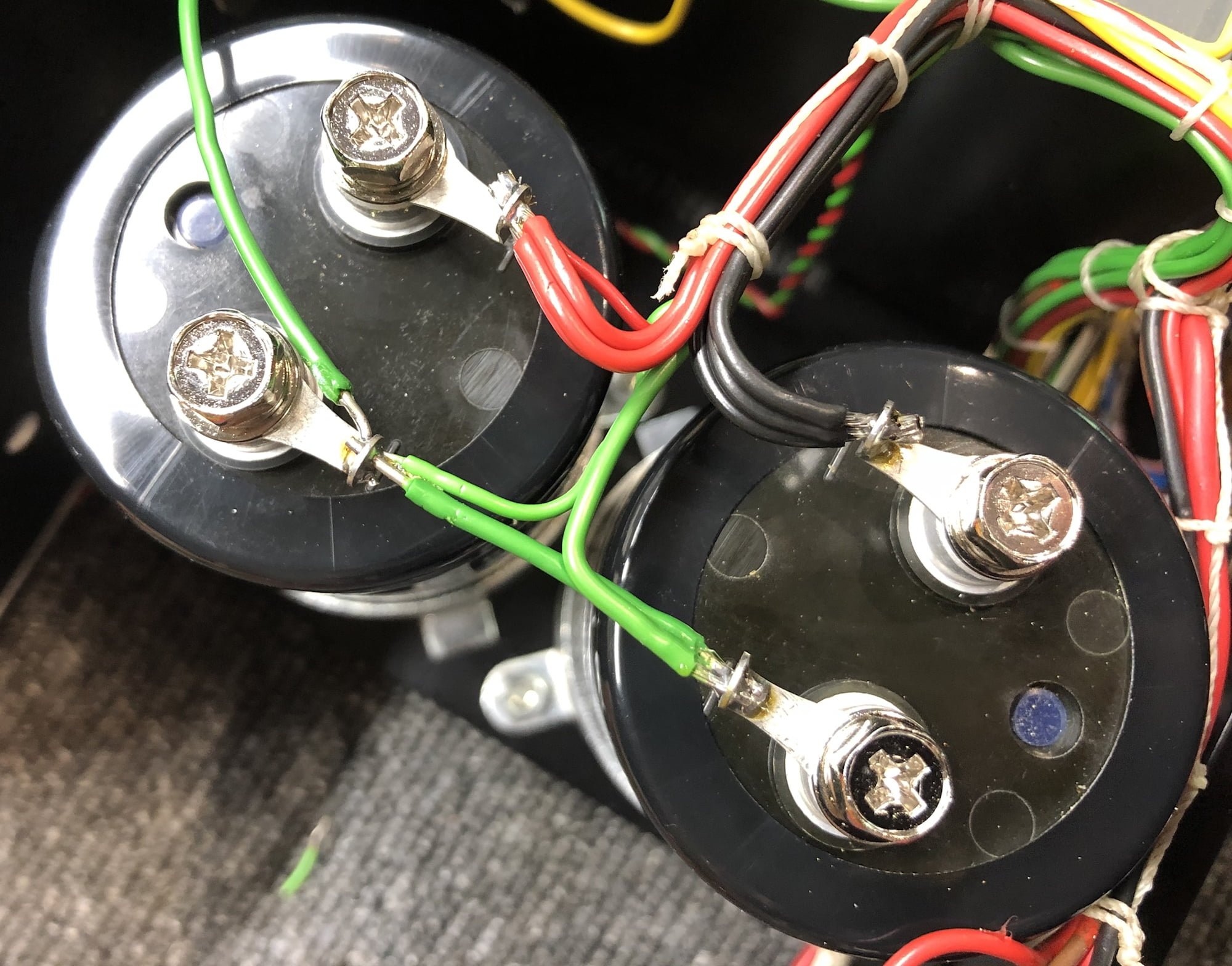
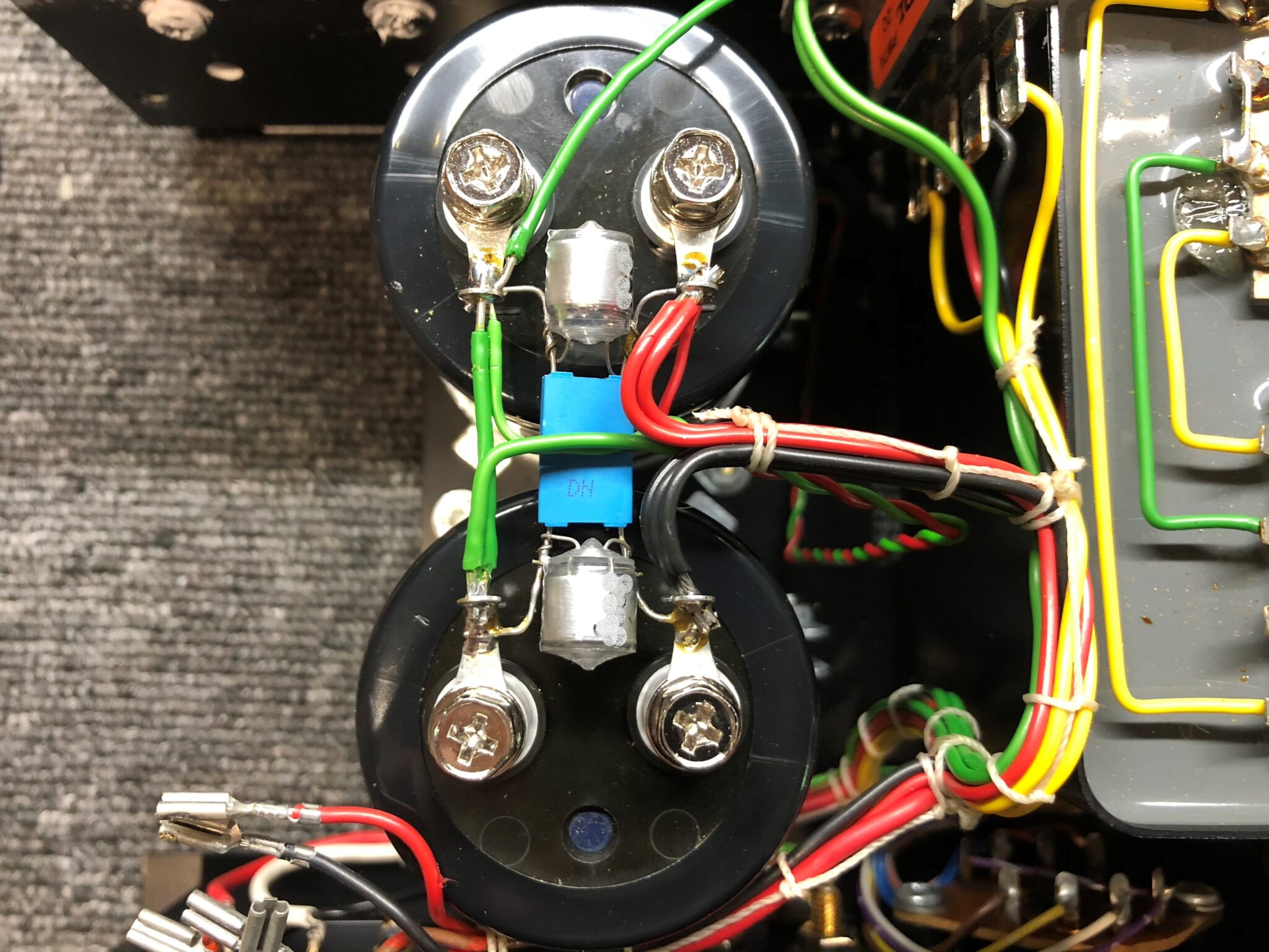
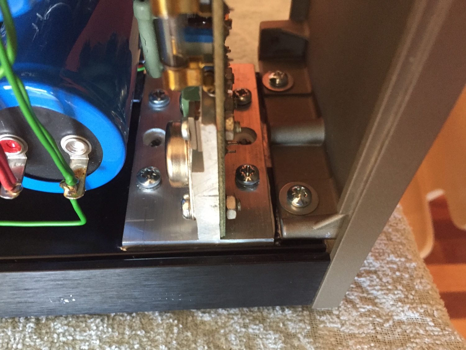
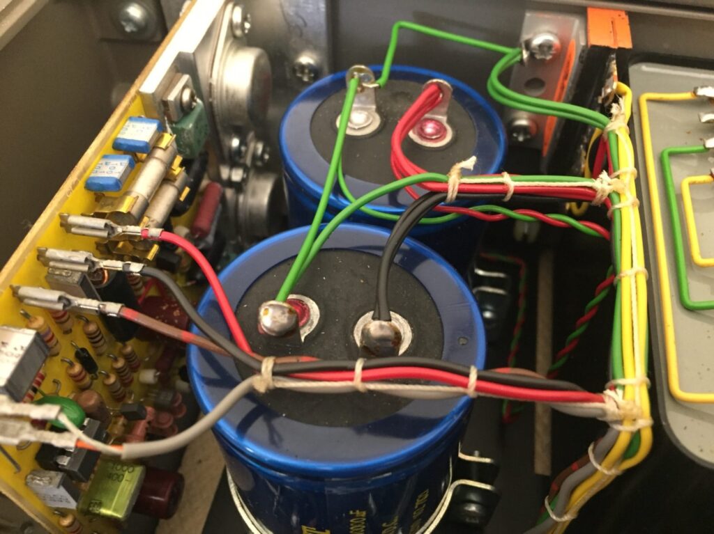
The remaining important mod with this particular Quad 405-2 was to replace the original filter capacitors with modern, higher-spec parts. STC branded 10,000uF @ 63V parts came factory-fitted. I replaced these with premium Kemet capacitors. The Kemet parts sound better and are rated for much longer service life. Before doing so, I examined the increased inrush current to ensure this was within the limitations of the diode bridge.
In some 405 and 405-2 upgrades, I now fit even better computer grade Illinois Capacitor parts, shipped to me all the way from the USA! These awesome capacitors are a real bonus in terms of the extra bass control and authority they provide, in combination with the other improvements I incorporate into my current resto’s.
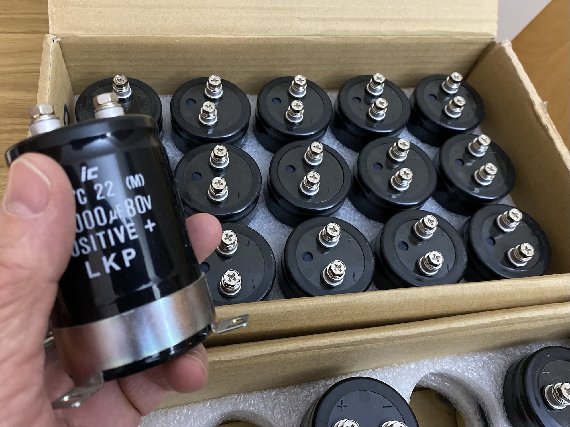
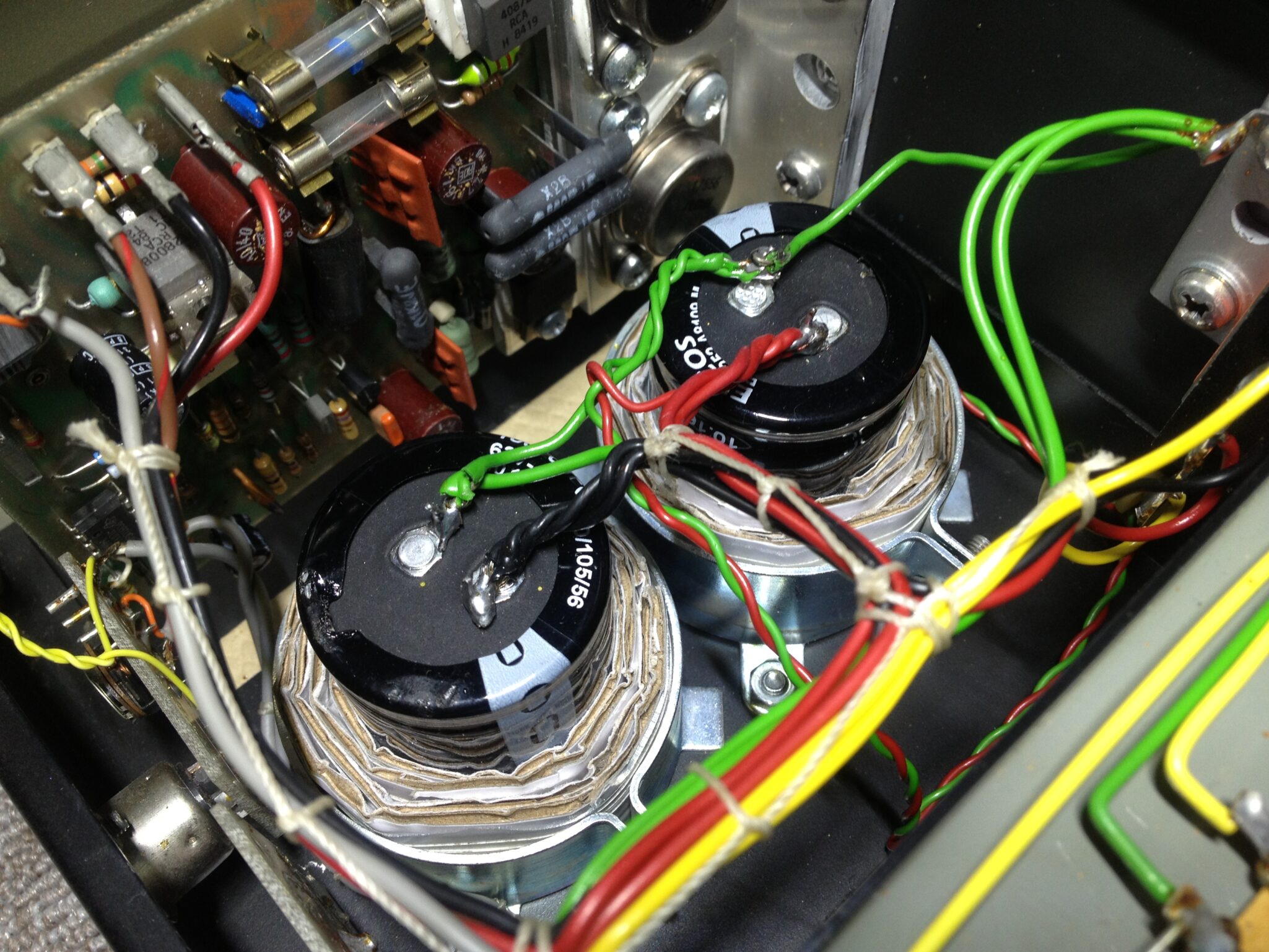
The original STC filter caps measured quite poorly. Capacitance was OK, but ESR was quite high for large caps. We should see an ESR of very close to 0 Ohms for large caps, measured using a proper ESR meter. The STC caps measured around 0.5 Ohms, which is too high. The new Kemet parts were as close to zero as you can get, at around 0.01 Ohms, plus they have 50% greater capacitance, so this is a worthwhile improvement.
The Chassis
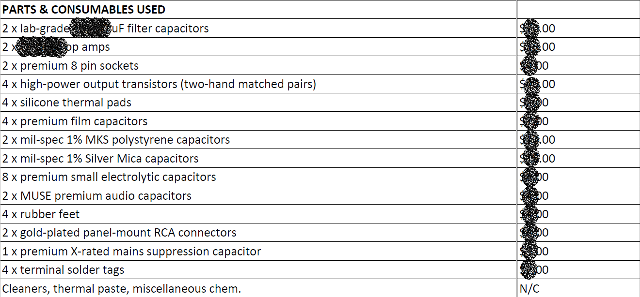
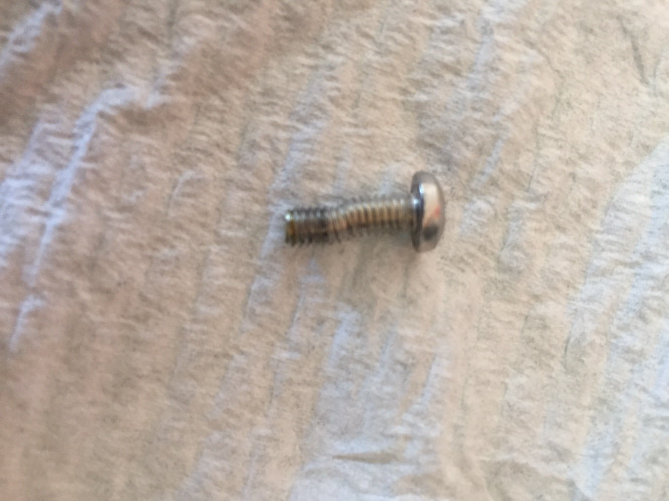
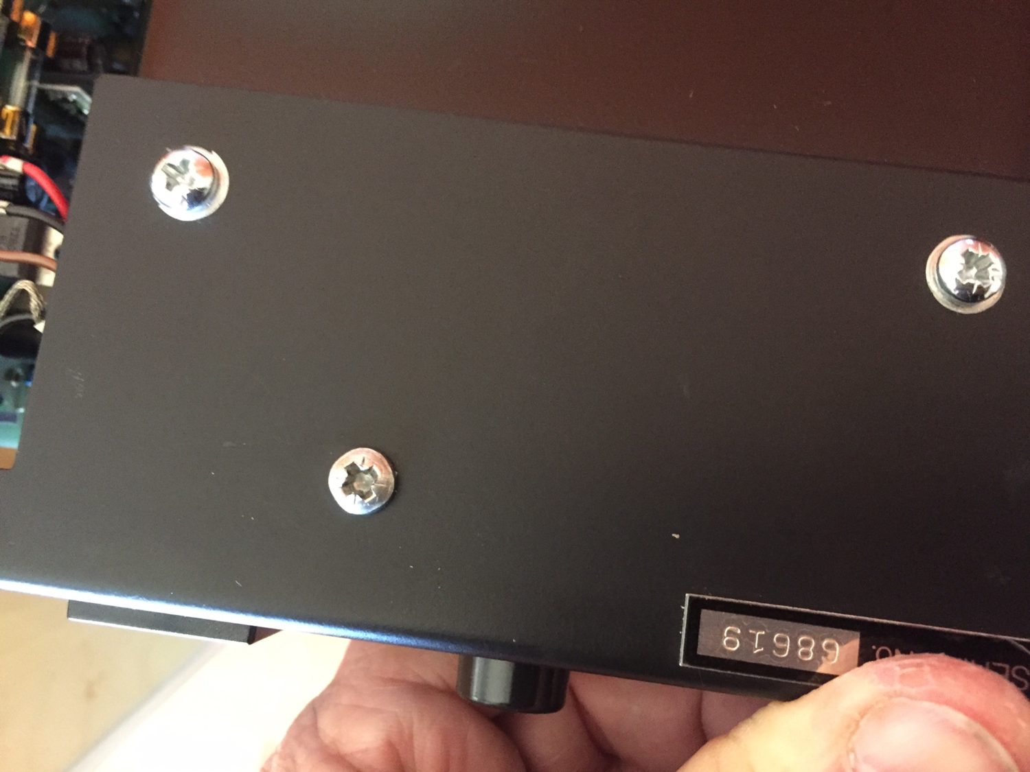
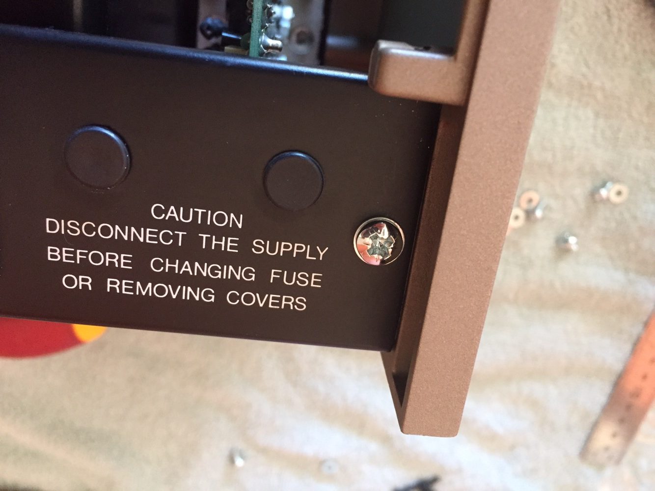
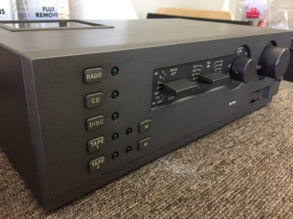
To complete the Quad 405-2 restoration and because of the damage incurred during shipping, I decided to replace the screws with new zinc-plated parts. New fasteners were easy to find at my local fasteners supplier, yours too I’m sure. They made a big difference to the appearance of my Quad 405-2.
The last thing is a new side panel to replace the dented one, ordered from Quad UK and on its way. That isn’t here yet and so does not feature in these images – yet!
I hope you’ve enjoyed this Quad 405-2 restoration. If you would like me to take care of your Quad 405 or 405-2, you need only visit my contact page.
Discover more from LiQUiD AUDiO
Subscribe to get the latest posts sent to your email.

Mike,
Since you have done the hard work on this, could you tell me the Mouser part number for the large 15,000 µF capacitors?
I have one of these 44/405 Quad combos which I bought on my way to Australia in 1981 and it is still going strong. The only thing I had to replace in 405 were the two pairs of electrolytics (47µF & 100µF) which dried out and made it hum. I also fix audio in Wanneroo and it looked bad when my own amp in the workshop badly hummed. Now is much better but when I really crank it up there is still some residual hum which I am hoping these large things will fix.
Cheers
Roman
Hi Roman
Thanks for making contact and I think we’ve perhaps chatted on the phone before – you rang me about fixing your oscilloscope, was that you? Anyway, that parts order was many orders ago so I can’t tell you what the part number was without some digging around unfortunately. You’ll be able to find these though by taking some measurements and using the parametric filters in Mouser. As I recall, they were about $10 each. There are of course lots of other options, but Kemet parts are superb quality and these have a lug style that allows re-use of the existing wiring set-up, for skilled solderers! Definitely worth doing.
Also be aware (if not already) that the 405 is notorious for hum if its been messed with and not wired correctly. They can hum for example when RCA connectors are changed. Depending on board version, this can be quite an annoyance. The trick is to pay very careful attention to the schematic for your version and check the ground arrangement and wiring of the RCA connectors.
Let me know how you go!
Cheers
Mike
Thanks Mike for your response.
Will search for the caps at Mouser site.
We did chat one day but I don’t think it was about the oscilloscope. I have two of them and they both work fine.
I might have been interested in your Laser power meter. I seem to be mainly fixing CD players and whereas in Philips based machines it is not so crucial, Sony and Sanyo based units have a myriad of pots to adjust and a meter could come in handy (perhaps). They are about $150 to $200 at Wes and I do not know how useful they are. I currently have one of the Roksan Caspian players with Sanyo mech and board and it is time to bite the bullet and start working on it :-).
If you have a free afternoon one day, why don’t you come over to Wanneroo for a coffee and a chat (and maybe a glass of the vino)?
Roman
Hi Roman
No problem, yes a laser power meter is a very handy thing to have, I also fix a few CD players, don’t you love the ones with all the adjustments for tracking and focus?! I think the Roksan players are particularly horrible to work on, I hope this one is not too bad for you. I’d would definitely like to drop by for a chat, let me know your details (email me at liquidaudio@iinet.net.au) and we can arrange it!
Cheers
Mike
How does it sound on NS-1000?Valve like?
Hi Paul, yes you’ve hit the nail on the head there, that’s more or less how I would describe it. Very good match, helps tame some of the NS-1000 sparkle. Mike
Hi. Why did you not upgrade the stock bridge rectifier? It is only rated at 7 amps. Do bridge rectifiers not affect audio quality?
Thank you. Richard.
Hi Richard and thanks for your question. There’s a long answer to this and a shorter one, which I’ll try to stick to here. The 405 is rated to draw a maximum current of 2.5A @ 240V, 5A @ 110/120V. I have looked up the bridge rectifier previously and it’s rated for at least 7A, more from memory, but either way, this is way more than the current draw of this amp under real musical conditions. Remember that the rating of 2.5A is for a slow acting fuse, so there’s some integration of current over time there. In the real world, the bridge is just coasting along. In addition, it’s compact and has a nice heatsink tab on it. I always add thermal compound underneath, so that they are really well coupled to the heatsink. One DOES have to consider the inrush current imposed on the bridge if/when increasing the size of the main filter capacitors. I’ve done the calcs on this and the bridge was good for even the fairly major increase I made on a customer amp recently, to 2 x 18,000uF. This will impose an increased load on the bridge though, so be aware of this. In terms of ‘upgrading’ parts, we really do have to be careful and focus on the science. Other bridges won’t really sound any different to this bridge, but what we do around the bridge is important and will affect the sound. For example, installing snubber caps across each diode in the bridge is an excellent idea and will improve the sound of the amp overall. Thanks again for visiting and don’t hesitate to ask more questions if you have them!
Thanks! Concerning the 15000uf caps, i was told big caps are slow to charge and discharge therefore give a slow kind of sound, that paralleling a few small caps is better as these are faster. Naim audio do this as mentioned on their site. Do you think there is any merit to this, perhaps at higher frequencies.
2. There is the advantage of lower esr and higher ripple current with paralleling, do you think this may help to increase sound quality.
Thank you. Richard.
Hi Richard, thanks for your questions. Unfortunately, these comments that people make, such as that big caps are slow to charge or sound slow are just not technically or actually correct. The capacitors stay charged while the amplifier is running and in terms of speed, some of the worlds greatest amplifiers, like those made by Mark Levinson, Krell, Accuphase and so on, use a small number of very large caps, to great effect. These amplifiers definitely cannot be classed as slow in any sense. More capacitance is generally a good thing though, and this can be achieved by multiple small, or a few large caps. Smaller caps are cheaper and easier to implement in a circuit, this may explain why some manufacturers have gone down this route. Multiple good small caps will also present a very low power supply impedance which is a good thing. Super low impedance, ESR and high ripple current can also be achieved with correct board layout and implementation of a few very large caps, so no real advantage there. Both can achieve the desired outcome if correctly implemented.
hello there Mike,
I have a 405 and a 303 and I connect the power plug from the 405 to the back of the 303, so when I turn the 303 on it also turns the 405 on. but the 303 mains plug says max. 2A. and the 405 as you mentioned gets to 2.5A maximum current. do you think this can be an issue to the power circuit of the 303?
thank you,
Filipe Enes
Hi Filipe, no I think that this arrangement will work OK. Better to give the 405 it’s own separate power of course, but if you leave it as is, the 303 should be fine.
thanks for your quick answer. thinking of restoring my 303, any advice on where to focus my attention? (promise this will be my last question :))
Hi Filipe, the 303 is a fairly simple pre, but the usual areas should be addressed – switches and controls, caps which tend to leak in these, power supply and so on. There are a few useful improvements that can be made. Be careful as leaking caps often cause board damage, which must be repaired.
Hi Mike,
What are components which are included in the Quad 405-2 upgrading kit and what’s the cost of it?
Also let me know the difference between 405 – 2 and 405 – 3?
Please Email me.
Hi Lalith, thanks for your message. There is no Quad 405-2 kit, we don’t sell kits for a few reasons, check out my FAQs for more on this. The work we do is tailored to suit the customer and equipment. I am happy to improve your Quad 405 for you, but I’d need it here to be able to do that. If you live locally, get in touch when I reopen after January 15 and I’d be very happy to chat about your requirements!
Hi Mike,
I have a 44Mk1/405-2 i wish to service. In your guide you have replaced some of the caps on both units but it would be helpful if stated which caps, values and locations, with this information i can acquire the correct parts before hand and service the units in one go so reducing the ‘down time’. Serial No are:- 4022 and 43466 for pre and power respectively.
Thank you in advance,
Andrew.
Hi Andrew and thanks for your question. I’ve not included all the details as that isn’t really the aim of my article. There are many sites out there that cover the DIY angle, mine is more about showing the sort of work I do for my customers and highlighting best practice vs common practice, as well as giving back to the hi-fi community in general with reviews, tech info, inside info etc. You can access the service data in many places including via my article from memory though. Just be careful, take your time and use the best tools and parts you can, along with expert sources of info.
Hi MIKE,
I just bought 405-2 ,34,fm4 witch is have obly 110v only ( without multiple switch 100:240) and the previous owner put it in 220v
They aren’t dileverd yet
Wht r u think mike what happened to it?