In this article, I discuss the history of the LM3886/chip-amp/gaincard and run through building my own dual-mono LM3886 gainclone amplifier.
The LM3886 is one of Texas Instrument’s single-chip monolithic amplifier integrated circuits. It’s almost an entire amplifier-on-a-chip, with only a few extra parts required to build a fully functional, high-performance amplifier.
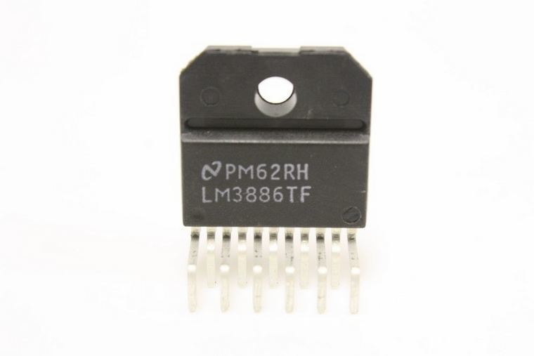
The LM3886 features low distortion (less than 0.1%) and respectable power output into easy loads. Each mono chip will output around 50 watts RMS into 8 ohms, with adequate heatsinking and power rails. It delivers a little less power into 4 ohms, though this depends on the voltage you feed the chip.
Origins
The LM3886 gainclone concept goes all the way back to 1999 and a company called 47 Labs. The designers at 47 Labs introduced an amplifier called the 4706 Gaincard. The Gaincard was well-reviewed at the time but caused considerable controversy. It sounded great, despite not using much power supply filtering and hardly any parts.
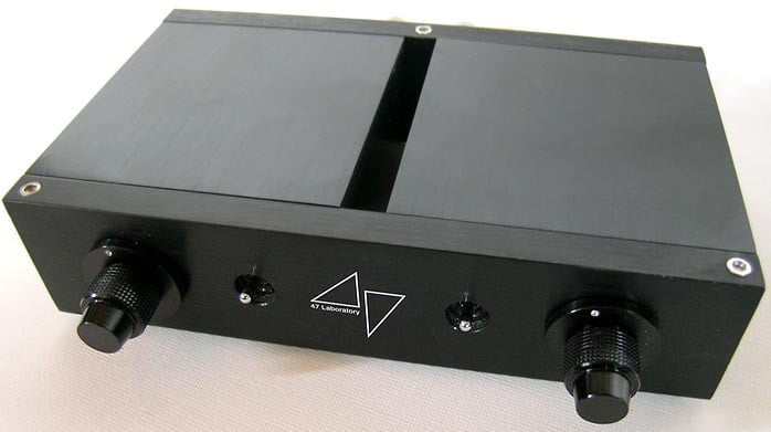
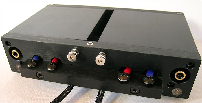
The Gaincard cheekily flew in the face of conventional amplifier design. Most of the controversy, however, came from the sealed 47 Labs chassis and what was hidden inside. The sealed chassis and $3300USD price tag naturally made owners keen to take a peek, and when someone finally did, the sh%t hit the fan…
Enter the Gainclone
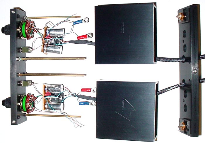
The audio community quickly discovered that the Gaincard, retailing for over $3K, was nothing more than a couple of LM3886 integrated circuits and a few bucks worth of parts. Sure, this was creative, ingenious even. The total signal path was only a few centimetres long and the chassis was beautiful, but owners felt duped, having paid thousands of dollars for a very nice chassis and some very cheap parts.
The DIY audio community became interested at this point because people realised that they could create clones, with perhaps even better sound than this expensive, well-reviewed amplifier. And so was born one of the great DIY audio phenomena of recent years – the gainclone!
My Project
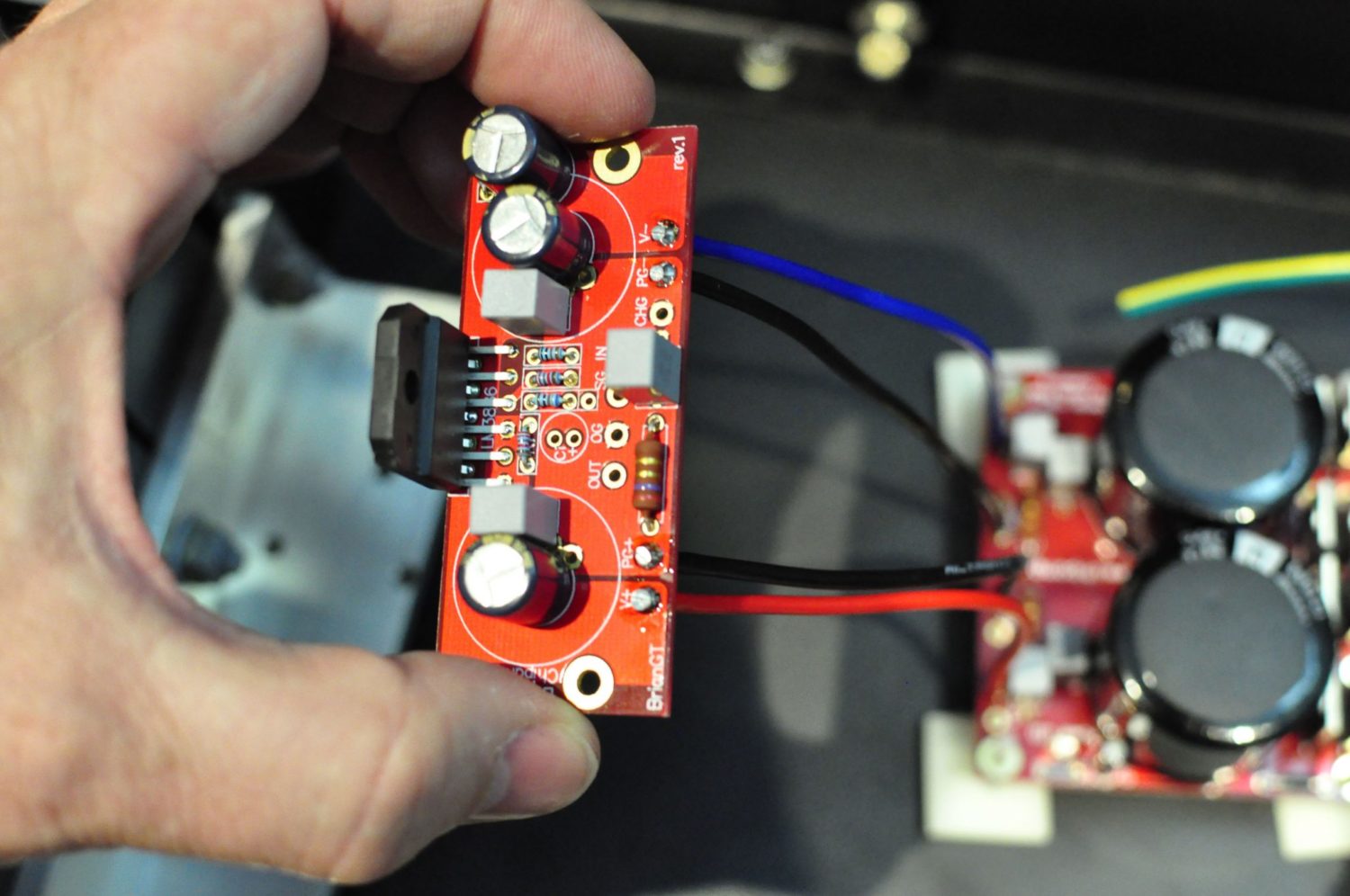
There are/were several LM3886 gainclone kits available online, like this and this beauty, but I like the set of boards and parts I got from the now-defunct chipamp.com. The PCB and parts quality are excellent and, after extensive research, I found that this was the best of all the kits available at the time.
There are some excellent online resources, including this new one all about building LM3886 amplifiers, from Circuit Basics.
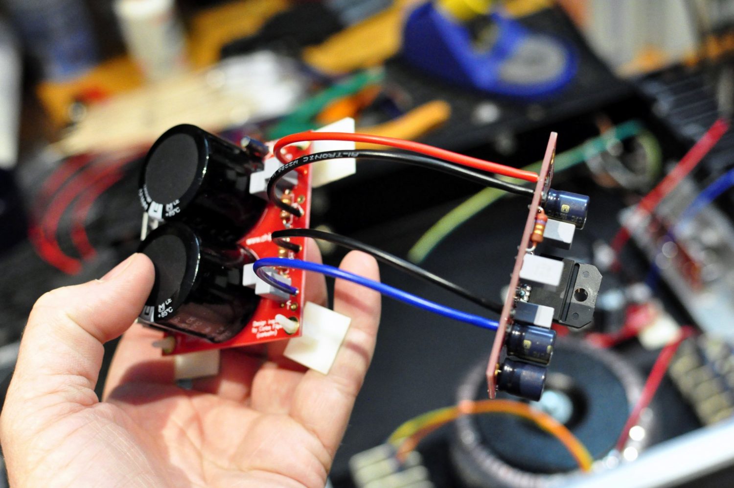
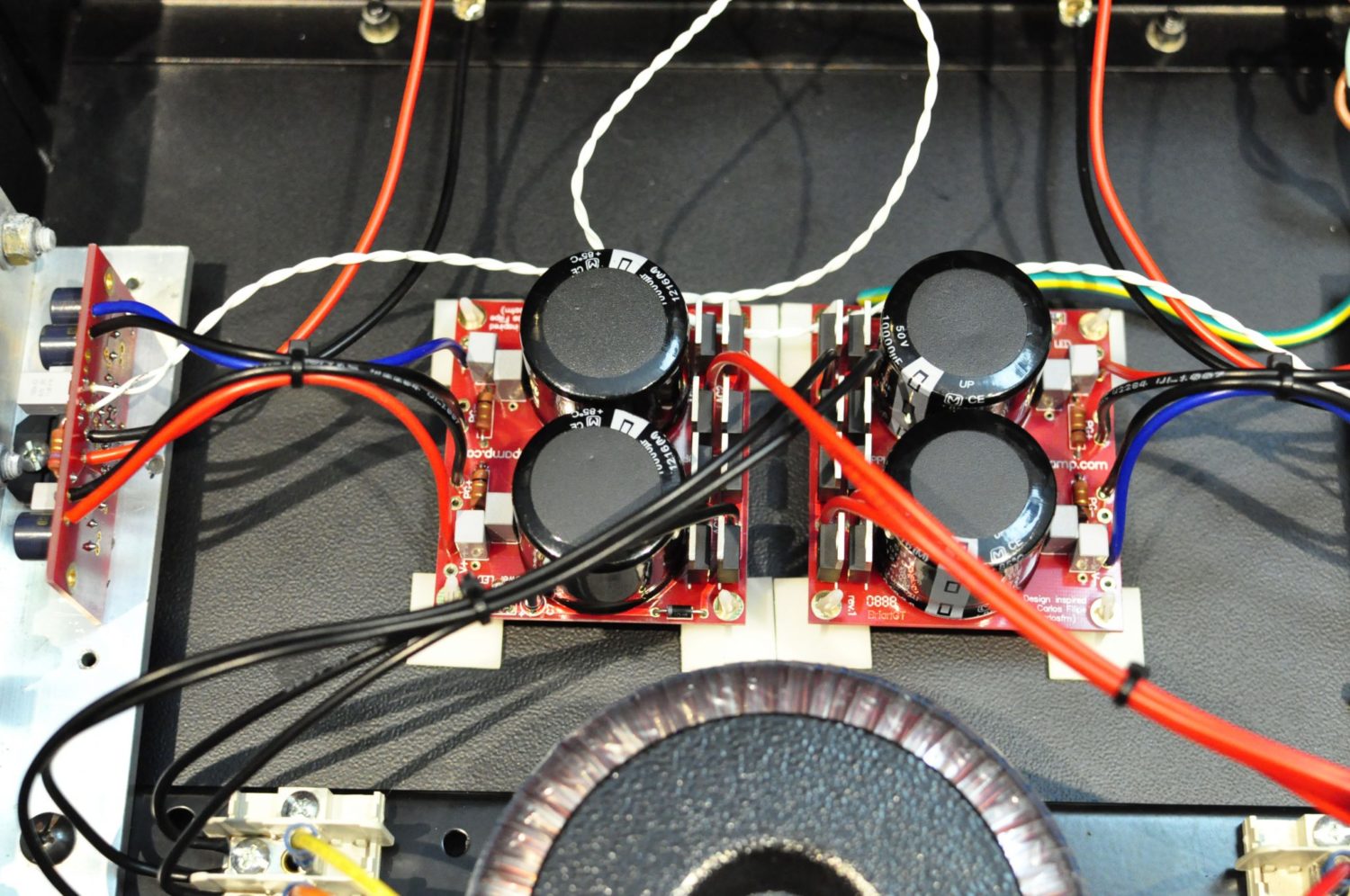
Everything was very easy to assemble and the Chip Amp kits include quality 10,000uF Panasonic filter capacitors, quality resistors and other passives. The traces are gold-plated and boards are fibreglass construction.
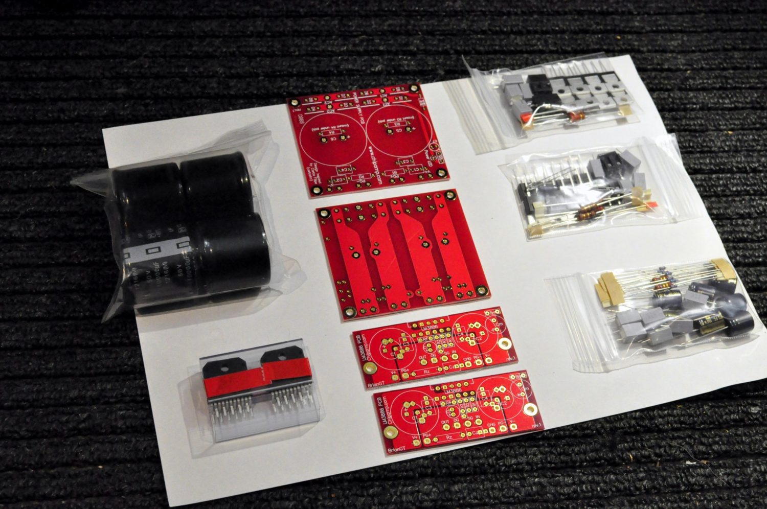
I was going to use two spare 100VA transformers with dual 12V secondaries, wired in series. The problem was that the 12V secondaries of these 100VA transformers wouldn’t be ideal in this application, yielding around 17V DC, before diode losses.
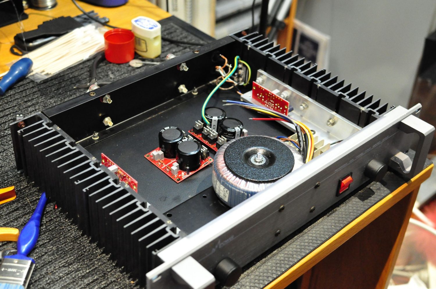
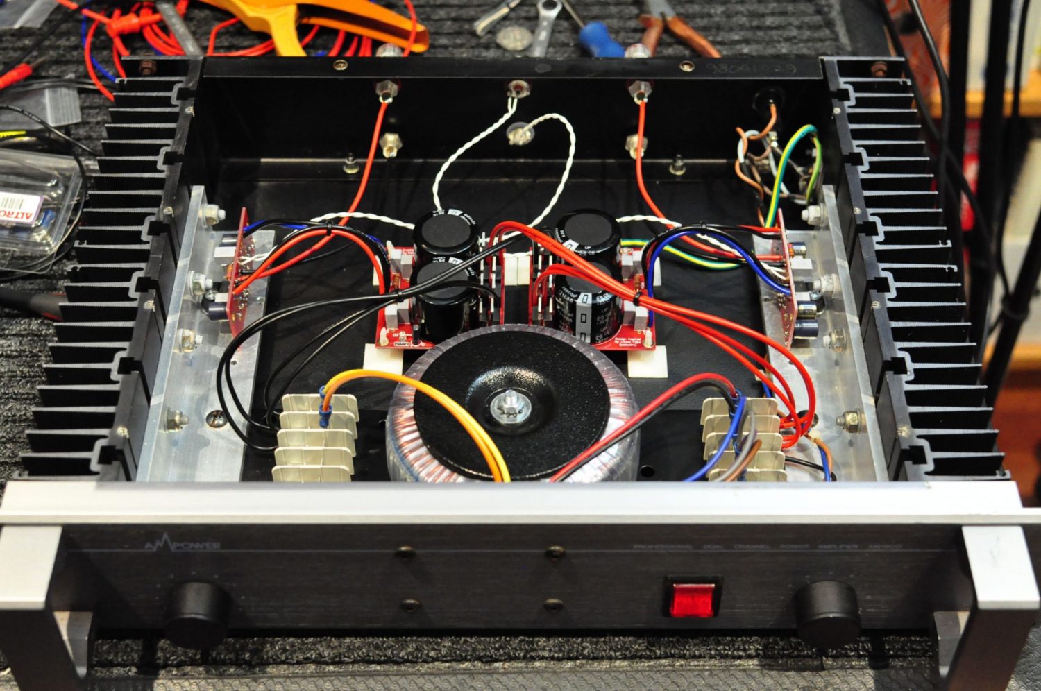
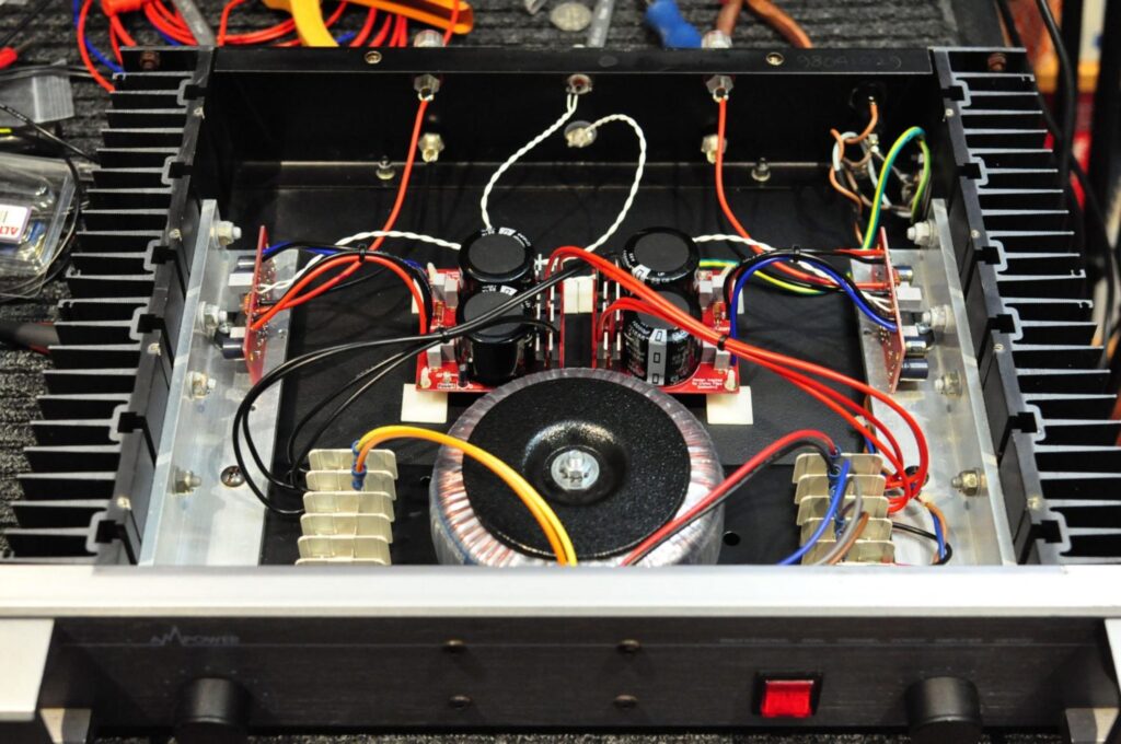
Instead, I decided to use a single 300VA transformer, with dual 25V secondaries. The amp is still configured with a dual-mono layout, the secondary voltage is now correct for driving an 8-ohm load and the single toroidal transformer mounts nicely where the old one did in this chassis. The 25V secondaries rectify up to around 35V (25 x 1.414), minus diode losses.
I decided to use this old amplifier chassis I had lying around:
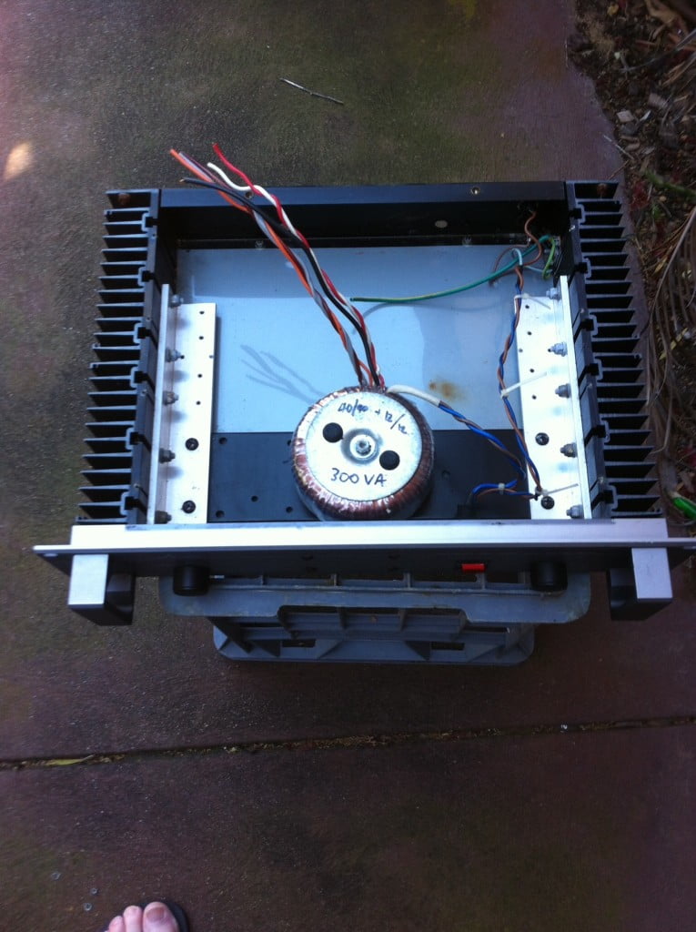
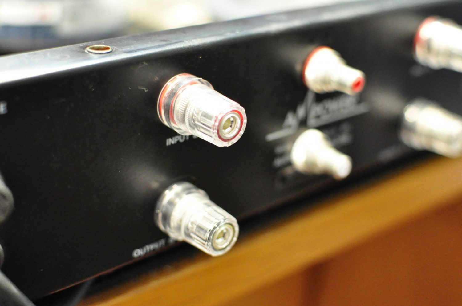
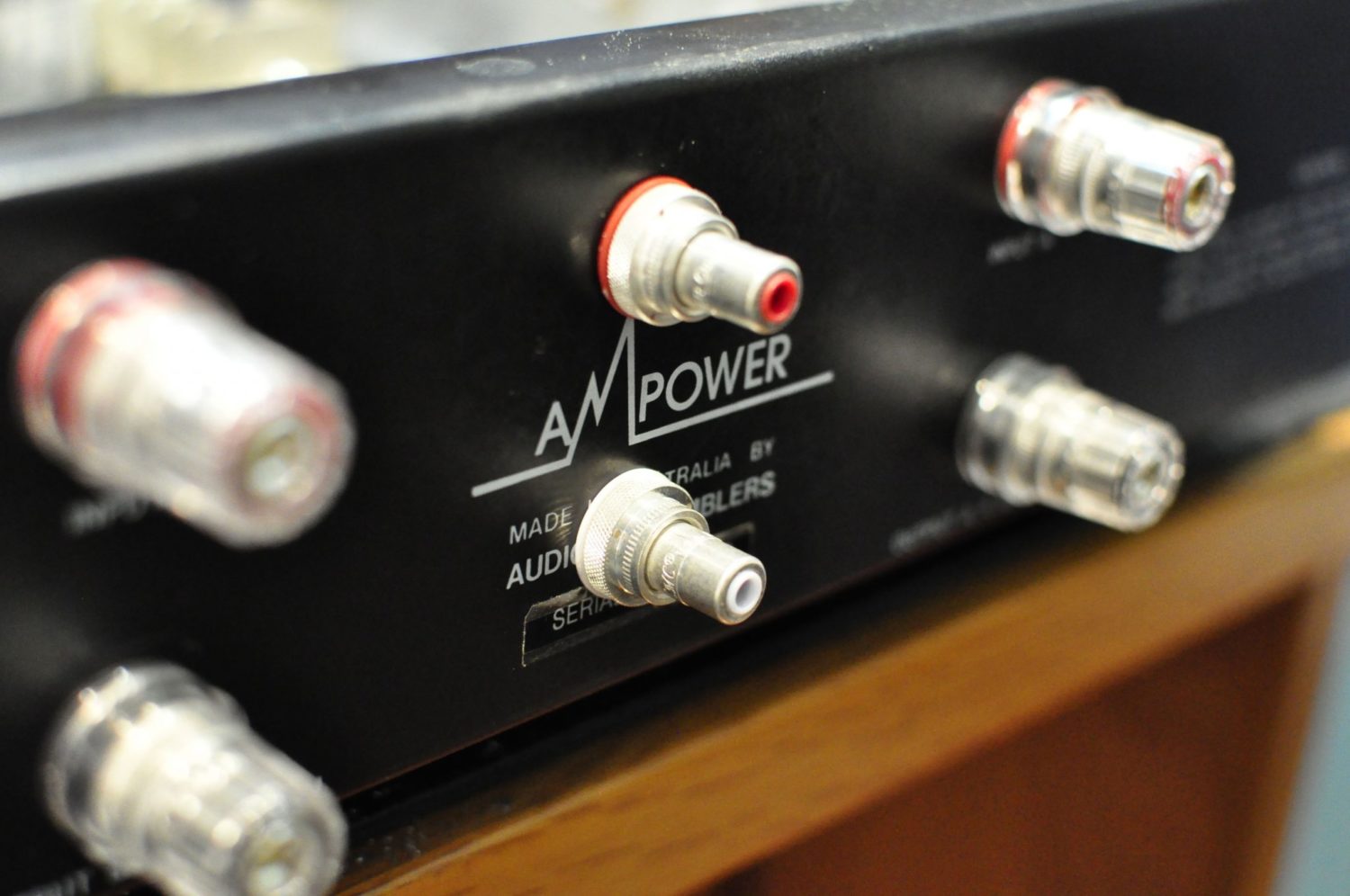
The next few pictures document my preparation of the chassis, including fitting CMC silver speaker binding posts, CMC silver RCA jacks and getting the heatsink mounting set-up.
The Build
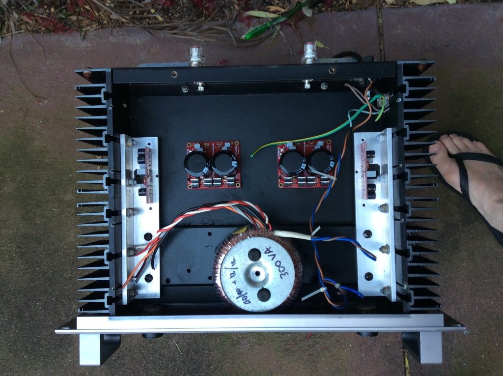
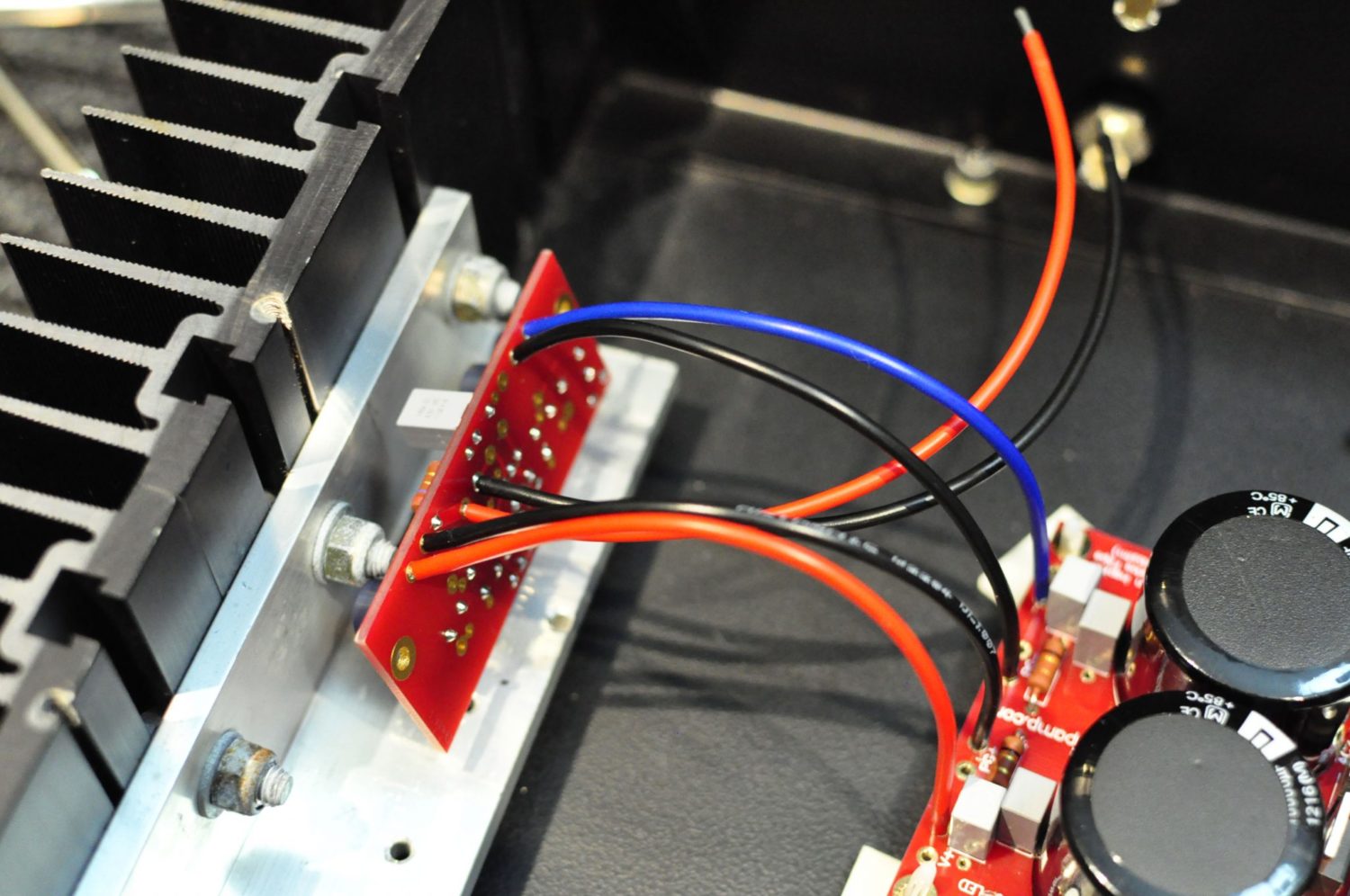
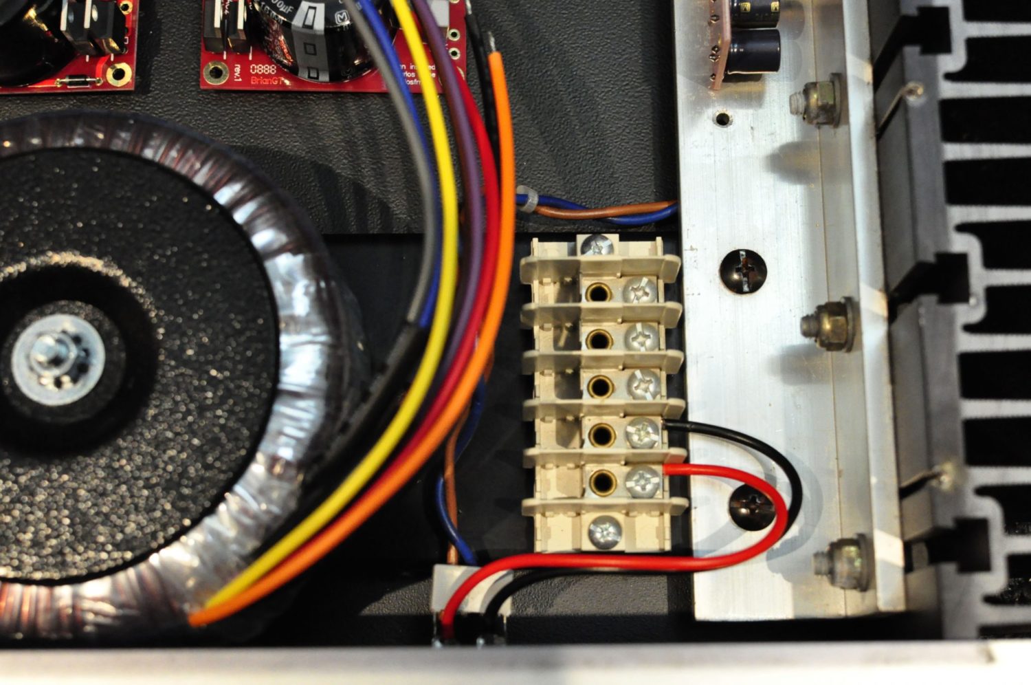
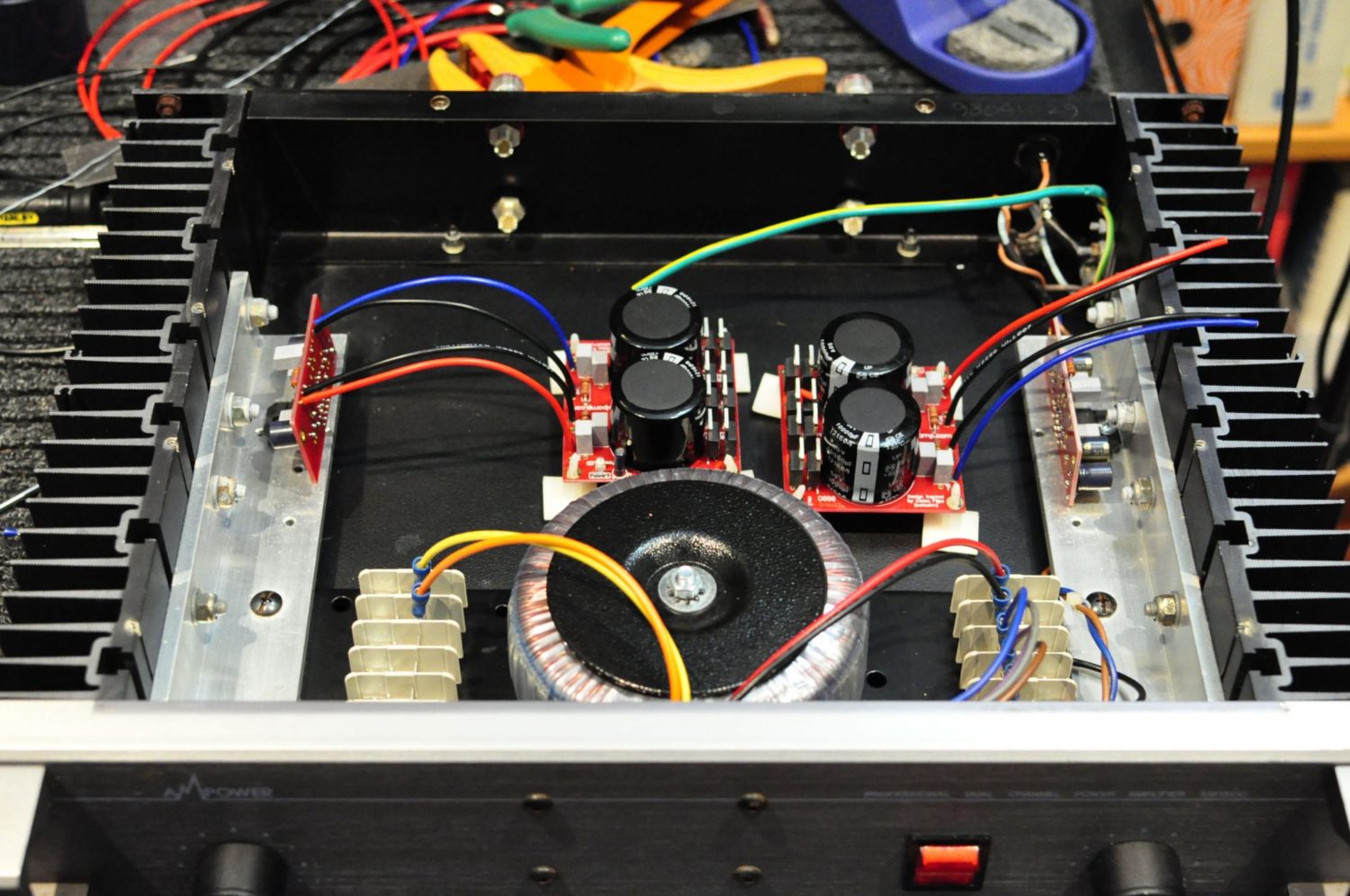
Performance & Ground Loops
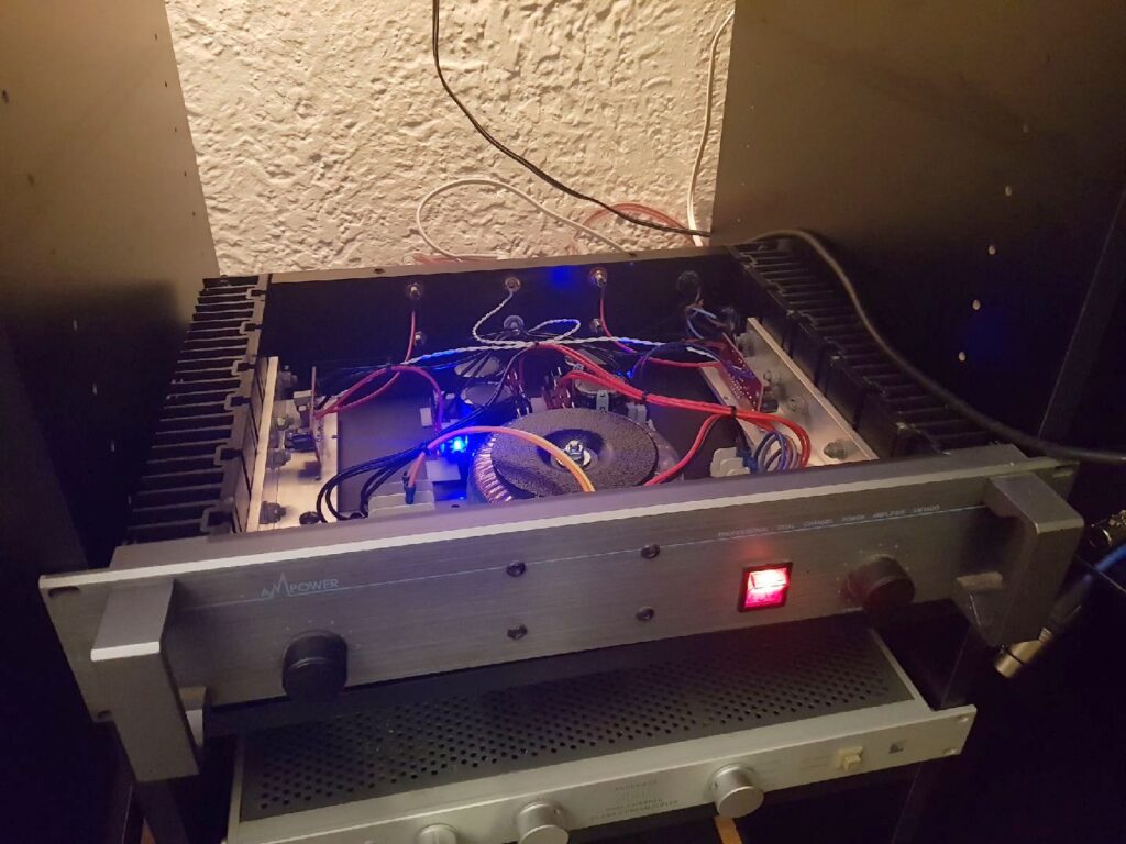
You can see from the above image that my LM3886 gainclone amplifier is up and running and she sounds great! This amplifier has air, tone and sounds smooth and relaxed. Perhaps the amplifier is a little bass-shy, compared to my Krell KSA-150, but realistically, in most installations, the LM3886 gainclone is a cracking amp.
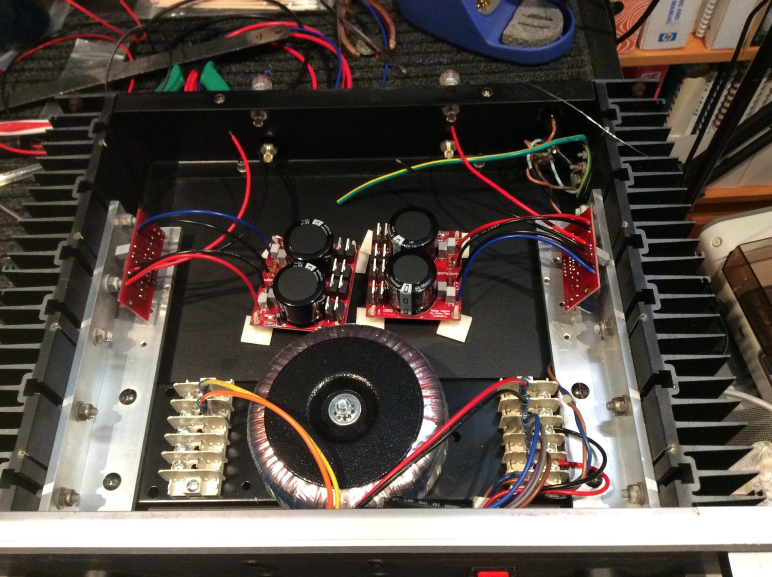
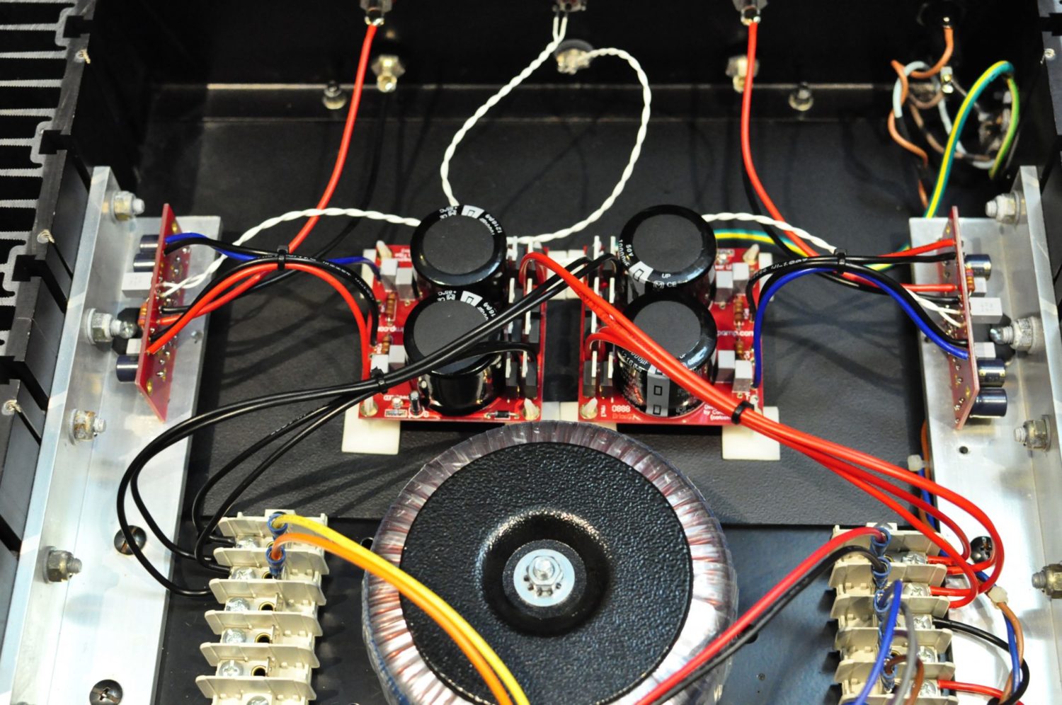
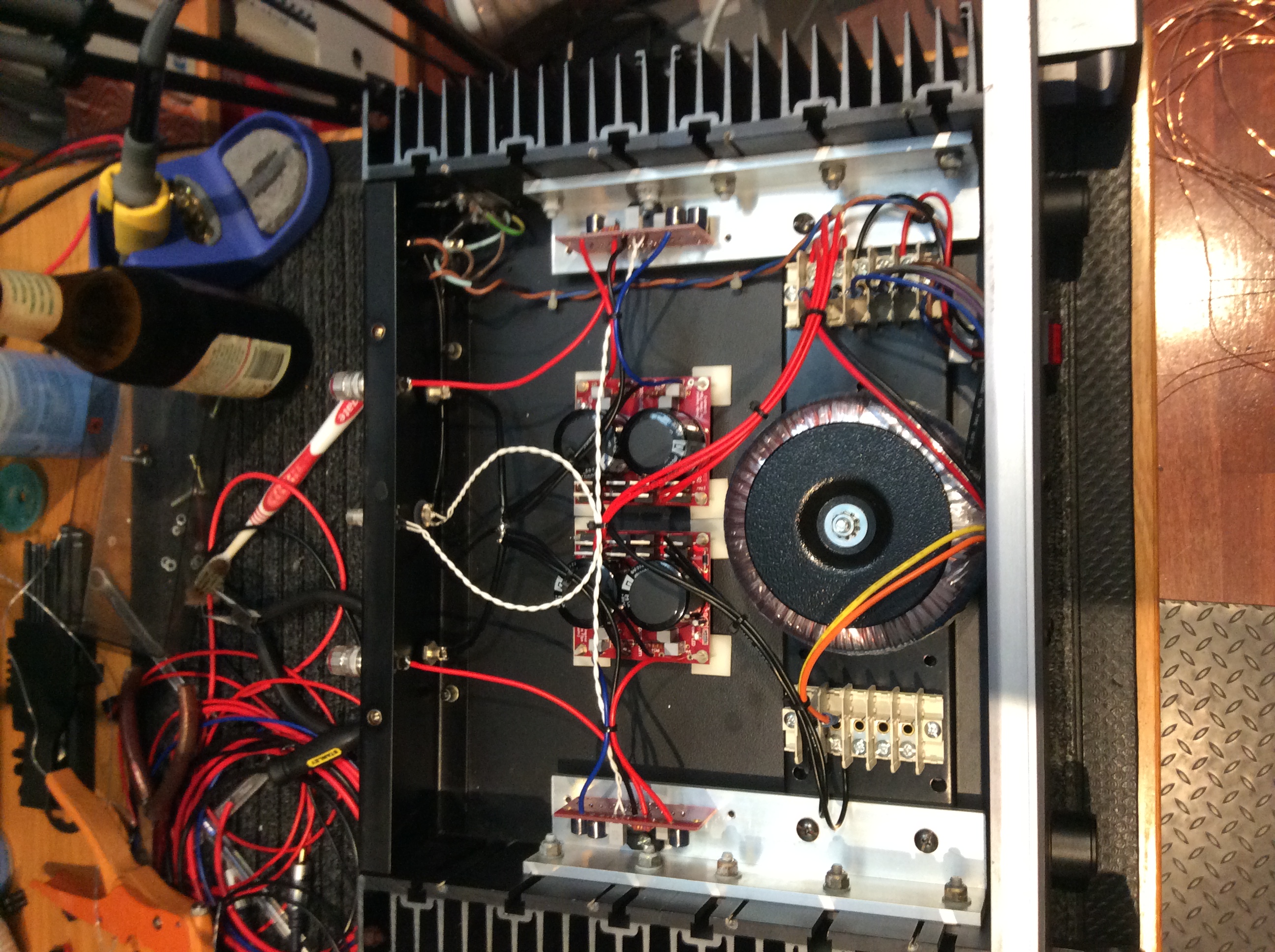
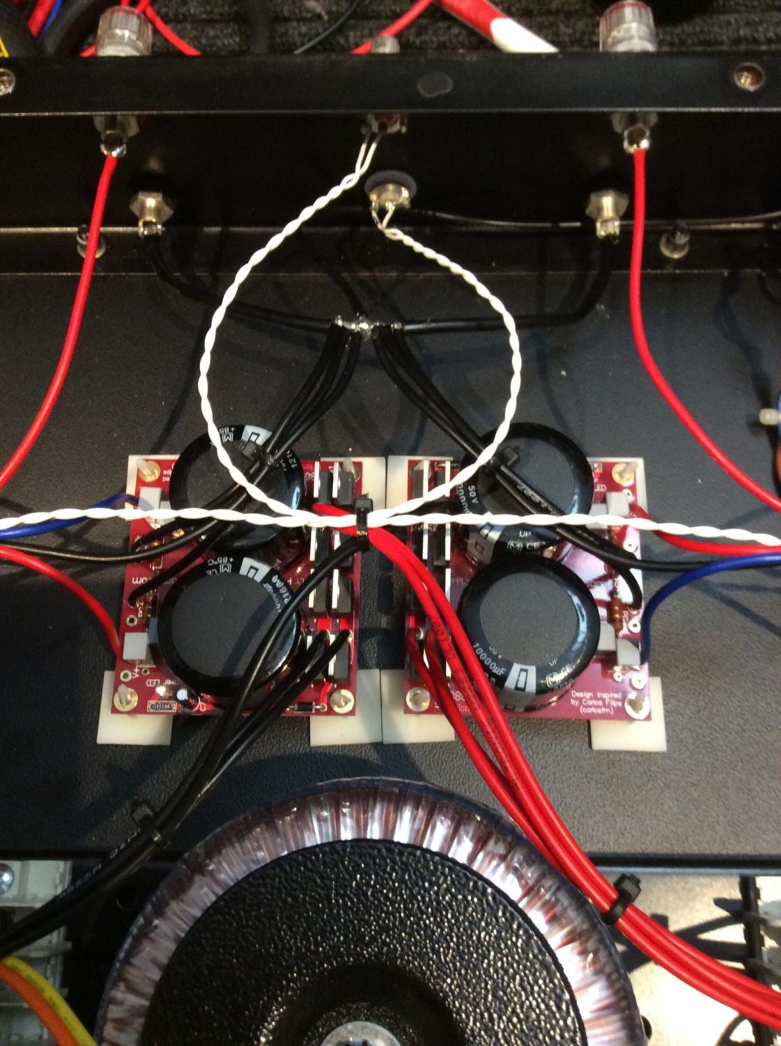
One small issue came about through not thinking carefully enough about the wiring layout. I experienced some hum on initial testing, which surprised me. After thinking and reading, I decided to modify the ground wiring layout, as shown in the images below. I rewired the ground wiring to include a true star ground. This would avoid the multiple earth returns of my initial layout, which caused the hum.
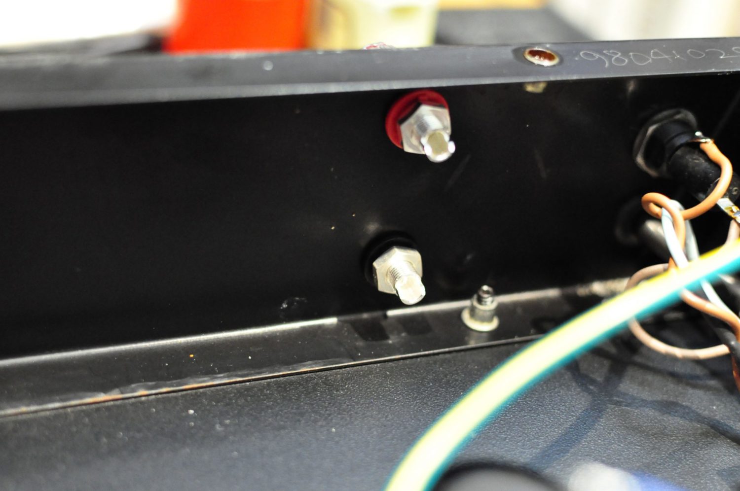
Look at the image below, to the rear of the chassis near the inputs. I’ve added a thick buss bar, linking loudspeaker grounds, amplifier and power supply grounds. I connected the new ground buss to chassis-ground, where the line cord earth wire terminates. This arrangement is now totally silent.
Discover more from LiQUiD AUDiO
Subscribe to get the latest posts sent to your email.


Very Nice build , I to have a slight hum, two questions, did you remove the power ground from both + and – ground them to the star and then re ground them to the amp boards, i can’t see it in you picture, and did you tie all the speaker grounds to the same star point and then to the board, and the input grounds remain isolated. And you said you tied the ground to the mains ground but I can’t see that in the picture. I love the sound of these amps and I am really pleased that you had the time to document the ground issues
Thanks Sal, yes all power grounds need to run to the star ground point, rather than to the boards and then to the ground. All ground returns and speaker grounds connect to this central point that represents the lowest impedance node of the circuit. The signal grounds are connected to the amp boards as normal, they are referenced to the star ground and not carrying large return currents in this configuration. This is ideal as signal ground and power grounds are kept somewhat separate. They are not actually separate of course, but “staggered” if you want to think of it that way. Look carefully at the last picture – click on it to get the enlargement and you will see my star earth is connected by a wire to the chassis earth – it exits out the back of the start ground and heads to the right rear of the chassis where the mains earth is connected.
I completed the changes on both amps, dead quite and clearer. I have to thank you I really appreciate you posting this info. And it might be helpful if the folks at ChipAmp put these suggestions in their information. It really made a huge difference.
Thanks for all your help.
Hi Sal, very pleased to hear that the changes made such a difference to your amp and I’m glad I was able to assist!
Best regards,
Mike
This is one sweet amp. I love the Hakko as well.
Thanks Allan, yes I am still using the amp and I’m very happy with it. I have another that I am going to build sometime soon, this time based on the LM4780.
Excellent build! Star config ground is the only way to go, I had the same problem.
Always like a recycled case too.
When I built mine, before I went to star grounding, I was able to “fine tune” most of the hum away by slightly turning the toroidal transformer and listening for hum, then tightened the transformer down in the best place for minimal noise. Then I added the star grounding…
I also added an “input sensitivity” (volume) 2 gang potentiometer to the lines in, recycled from a 70s Sansui amp. This thing is dead silent, been running almost daily for 14 years now, no problems.
I made my own preamp, which is also absolutely silent, running it all into some 70s FANE monitors, it’s a match made in heaven.
Hi Ben, thanks for your comments. Star grounding really is the only technically sound way to go with any audio gear and your tip about rotating transformers for the lowest radiated hum is a good one. These are very quiet amps when set up correctly, I’ve been using mine as a power amp and have kept the signal path as clean as possible but either way, LM3886 amps are capable of great sound. My buddy is now borrowing mine while I restore his Krell KSA-200S! Regards, Mike.
Anyone know what happened to chipamp.com, which appears to be a dead URL, or whether the kits are sold elsewhere?
Hi Jim, they ceased operations some time ago. There were other kit vendors when I last checked, do a search and see what comes up. I remember I saw a European vendor at some point recently, could have been German…
Hi, any problem with transformer 25-0-25? I have this trafo too 300va, after straightening board i have 37,6 vdc for rail. Do you thing is possible to use this? I will use this pcb: https://es.aliexpress.com/item/4000869665736.html?spm=a2g0o.order_detail.0.0.3ea939d3GITBa3&gatewayAdapt=glo2esp
Thank you
Hi Francesco, best to check the documentation for the LM3886 as all this is covered, but anything up to about 42VDC per rail from memory will work. Less than this will produce less power of course.
Hi, so glad to have found your site here. Once I’ve got the following problem sorted, I’ll buy the LM4785 kit.
I built a BrianGT LM3886 double mono amp years ago, put a selector switch and Alps pot to make it integrated and sounded absolutely fine.
Recently though, one of the channels is intermittently muted and I don’t know how to find the fault so I was going to try and rebuild parts of it (starting with the amp boards).
On Mouser, they list two LM3886TF chips (albeit with a 2 year wait) one has the NOPB initials after the LM3886TF, what is that for? and is that essentially the same chip?
Also, you wouldn’t happen to have a parts list for thatNrianGT amp would you?
Many thanks and looking foward to building again.
Hi Julian, NOPB means ‘no Pb’ – ie no lead or lead-free.